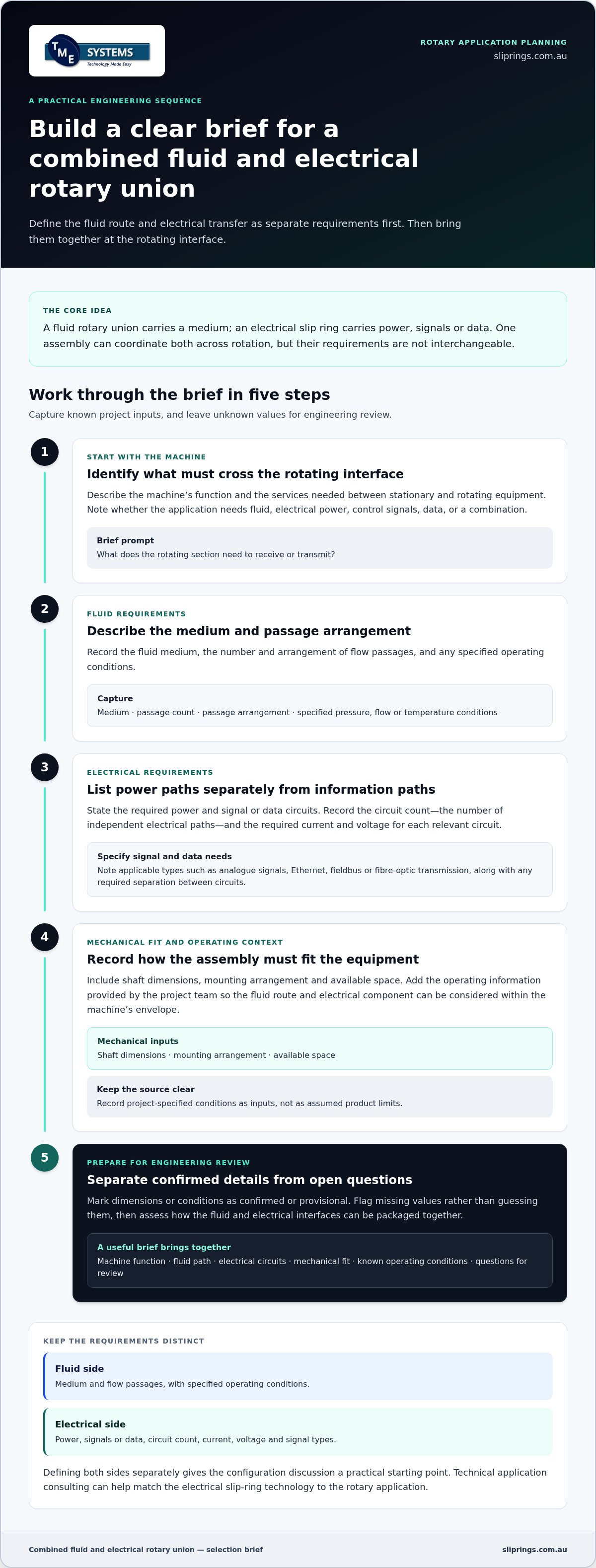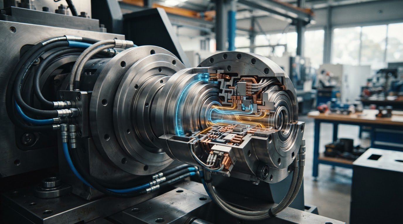
A combined fluid and electrical rotary union brings fluid routing and electrical transfer together across one rotating interface. The fluid connections and rotary electrical joint have different requirements, so each needs to be defined before the assembly is configured. Treating them as separate engineering needs helps prevent a mismatch when the components are integrated into machinery.
An integrated assembly is one possible approach, but it is not the only one. This guide compares integrated, standard and custom approaches, and explains what information helps define a suitable application. Assess fluid requirements such as medium, pressure and flow alongside electrical needs such as power, signals and circuit count, then consider mounting and operating conditions. TME Systems provides technical application consulting to help match the electrical slip-ring technology to the project, including consideration of Prosper Rotation slip rings. A clear selection brief gives the engineering discussion a practical starting point.
Key Takeaways
- Understand how a combined fluid and electrical rotary union brings fluid passages and electrical transfer together for rotating machinery.
- Record fluid-side and electrical-side requirements separately to make interface decisions clearer.
- Compare integrated, standard and custom approaches by their flexibility and the project information needed for selection.
- Build a selection brief around machine function, connection interfaces and known operating conditions.
- TME Systems’ technical application consulting can help match an electrical slip-ring technology to the rotary application.
What does a combined fluid and electrical rotary union do?
Rotating machinery often needs to stay connected to services mounted on stationary equipment. A rotating platform, for example, may need a fluid supply as well as electrical power or control signals while it turns. Separate lines crossing the moving interface can constrain the design, so engineers may bring the required transfer functions together in a rotary assembly.
A combined fluid and electrical rotary union pairs a fluid rotary union with an electrical slip ring for an application. It can transfer fluid, power, signals and data between stationary and rotating equipment. Each path has its own function: the fluid passage carries a medium, while electrical paths carry power or information. Integration coordinates these paths in one rotary interface, but does not make their requirements interchangeable.
How the fluid rotary union and electrical slip ring work together
The fluid rotary union provides a route for a medium to pass between stationary pipework and rotating equipment. The electrical slip ring maintains electrical connections across rotation, transferring power, signals or data through separate paths. These functions can share an assembly, but each has distinct interfaces and requirements. The Rotary Union Wikipedia overview also describes how a slip ring can operate alongside a rotary union.
That distinction matters during design. The fluid connection is defined by the medium and the passage it needs. The electrical side depends on the power, signals or data the machine must carry. Defining these functions separately makes it easier to identify what the combined arrangement must accommodate before deciding how to package the interfaces. A single assembly can bring the rotary connections together, but it still needs to suit both sets of requirements.
Where combined rotary assemblies are used
Combined arrangements are relevant wherever equipment rotates but still needs services from stationary equipment. The required combination depends on the machine’s function, not just its application name. Examples include:
- Water-treatment plant equipment: rotating machinery may require fluid routing alongside electrical connections for power, signals or data.
- Rotating bridges: a rotary interface can be considered where services need to cross between stationary and moving sections.
- Wind-turbine rotating assemblies: electrical transfer can form part of the rotary-engineering requirement, while fluid transfer depends on the equipment’s needs.
- Rotary tables, packaging machinery and indexing systems: the rotating element may need electrical connections, fluid supply or both, depending on its operation.
BGB Innovation assemblies cover power, signal, data, wind-turbine, water-treatment and custom rotary-engineering applications. The range of uses highlights why there is no single arrangement for every machine: a rotating bridge may have different interface needs from an indexing system. Start by identifying which services must cross the rotating interface, then consider how the fluid and electrical components can be arranged to serve that function.
Which requirements shape a combined fluid and electrical rotary union?
Start by documenting fluid and electrical requirements separately. This stops a clearly defined need on one side, such as a passage arrangement, from obscuring missing information on the other. Assess a combined fluid and electrical rotary union against both sets of inputs before selecting its physical arrangement. Record what the project specification states and mark unknown values for engineering review rather than assuming ratings.
Define the fluid path and mechanical interface
Describe the medium and the required number and arrangement of flow passages. Note operating information supplied by the project team, such as specified pressure, flow or temperature conditions, without treating those values as product limits. Then capture the mechanical envelope: shaft dimensions, mounting arrangement and available space. These details show how the fluid route must fit around the rotating equipment and electrical component.
If the machinery design is still developing, distinguish confirmed dimensions from provisional ones. A drawing or interface sketch can clarify where stationary pipework meets the rotating section and which clearances are fixed. Do not substitute a guessed passage layout or operating value for missing project data.
Specify electrical circuits and signal needs
List power circuits separately from signal and data circuits. The circuit count is the number of independent electrical paths needed for power and signal transmission. Record the required current and voltage for each relevant circuit as application inputs, not as assumed slip-ring ratings. A NASA report on an electrical rotary joint describes power transfer between rotating components, illustrating why the electrical interface needs its own definition.
Identify the signal types and data protocols involved. State whether the design requires analogue signals, Ethernet, fieldbus or fibre-optic transmission, and note any project requirements for separation between circuits. This lets the electrical configuration be assessed against the actual mix of power and information paths.
- Fluid: medium, passage count and arrangement, plus specified operating conditions.
- Electrical: power and signal circuits, circuit count, current, voltage and required signal or data types.
- Mechanical: shaft and mounting details, available space and interface constraints.
Keep values that have not been supplied visibly open. For example, record a missing current value as “to be defined” rather than selecting a figure from a similar machine. Apply the same approach to fluid operating conditions, data requirements and dimensions. This makes information gaps clear and helps prevent a preliminary assumption from becoming a design constraint.
Once these inputs are assembled, the electrical component can be matched to the application rather than chosen in isolation. TME Systems’ Prosper Rotation slip rings include standard and custom options, providing a basis for discussing the electrical side alongside the fluid and mechanical interfaces.
Integrated, standard or custom: how do the options compare?
Choosing an assembly approach is a matter of fit, not simply deciding whether one unit or two is preferable. An integrated rotary assembly coordinates fluid and electrical transfer in one package. Alternatively, a project can pair an electrical slip ring with a separate fluid rotary union. In either case, assess the mechanical and fluid interfaces alongside the electrical requirements. The Kadant guide to rotary joint integration with slip rings describes how these functions can be brought together while serving distinct purposes.
Use the comparison below to frame the discussion. It is a starting point, not a substitute for matching configuration details to the machine.
| Approach | Integration approach | Configuration flexibility | Information needed for selection |
|---|---|---|---|
| Integrated assembly | Fluid and electrical functions are coordinated in one rotary assembly. | Depends on the assembly’s available interfaces and configuration. | Fluid passages, electrical circuits, mechanical interfaces and available space. |
| Standard configuration | A defined assembly or component arrangement is considered against the project. | Bound by the configuration’s stated features. | Project requirements detailed enough to compare directly with the configuration. |
| Custom configuration | Components are configured for application-specific requirements. | Can address defined interface, packaging or circuit needs. | Clear drawings, operating inputs and a prioritised list of requirements. |
| Separate components | An electrical slip ring is selected for integration with a separate fluid union. | Each component can be assessed against its own function and interfaces. | Both component interfaces and how they fit within the machine. |
When a standard assembly may suit the project
A standard configuration is a useful starting point when its stated arrangement aligns with the machine’s mechanical and fluid interfaces. Compare the available passage layout and mounting arrangement with the project drawings. Then check the electrical circuit count, current, voltage and signal or data needs against the configuration requirements. A close match gives the team a defined basis for evaluation, but suitability still depends on that comparison.
When a custom configuration deserves consideration
Consider a custom route if the machine’s space, shaft interface, passage arrangement or circuit requirements do not align with a standard configuration. TME Systems works with manufacturers offering standard and customised slip-ring solutions, including Prosper Rotation slip rings. The range includes standard and custom conductive options. Technical application consulting can help define the electrical configuration for the project, without assuming a particular combined assembly design.
For a combined fluid and electrical rotary union, keep the decision focused on interfaces and requirements. A standard starting point may fit; a custom electrical configuration or separately integrated fluid union may better suit the machine. Let the application data, rather than the label attached to an assembly, guide the choice.
How should engineers prepare a selection brief?
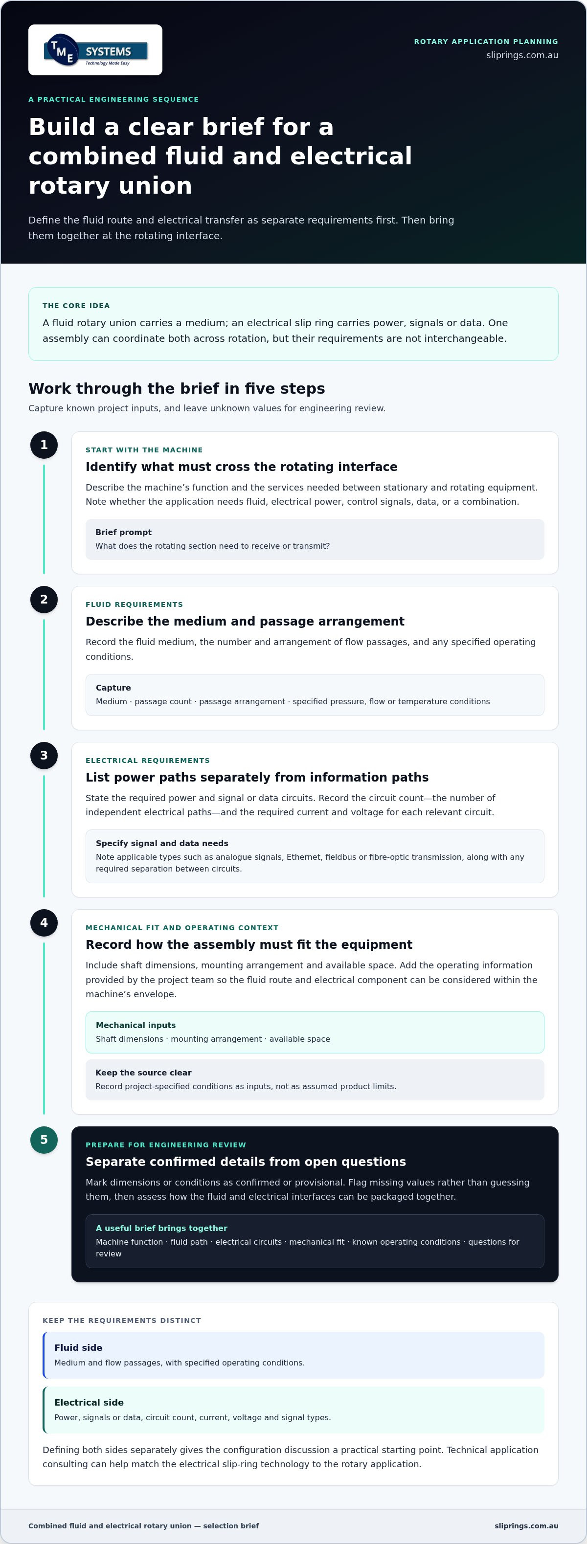
A useful selection brief joins fluid, electrical and mechanical requirements. For a combined fluid and electrical rotary union, describe the machine’s function and interfaces without treating unknown values as confirmed specifications. Keep drawings, interface details and operating information together, and mark each input as confirmed, provisional or not yet available. This gives technical review a clear record of what the project knows and what still needs resolution.
A practical sequence for documenting application requirements
Build the brief from the equipment’s purpose towards the proposed configuration. Use project documents and drawings as the source for recorded details.
- Describe the equipment function. Explain what the machine does, how its rotating section operates and why connections must cross the interface.
- Record the fluid path. Document the medium, required passages and arrangement, plus operating information stated in the project specification.
- Capture mechanical interfaces. Include shaft and mounting details, connection positions, clearances and available space shown in the machinery design.
- List electrical requirements. Separate power, signal and data needs, and note circuit count, current and voltage where specified.
- Add known operating conditions. Include speed and environmental inputs only when the project team has data for them.
- Identify open questions. Mark unavailable values and provisional details for consideration during engineering review.
Keep drawing revisions and interface notes aligned. If dimensions are changing, identify the current drawing version and label provisional measurements. A brief can still be useful when information is incomplete, provided the gaps are visible. This helps distinguish a confirmed design constraint from a value that remains to be established.
Review electrical technology against the application
Compare circuit count, current, voltage, speed and mounting style with the project’s documented requirements. Include the signal or data types required by the machine, and note environmental conditions that may affect component selection. Treat these as application inputs, not assumed product ratings. TME Systems’ technical application consulting can help assess slip-ring technology against the project’s electrical needs.
If low resistance and low electrical noise are priorities, liquid metal rotary connectors may be one technology to consider. These brushless rotary connectors use a pool of conductive liquid metal to maintain electrical continuity. Match the technology to the application requirements and the specific electrical function, rather than choosing it based on a general preference for one contact method. Record why the technology is being considered so it can be reviewed against the wider brief.
With requirements, drawings and unresolved items assembled, the engineering discussion can focus on how the electrical component fits the machine design. A clear brief also gives the project team a practical reference as interfaces or operating inputs develop.
How can TME Systems support the electrical side of a combined rotary application?
A combined fluid and electrical rotary union brings separate transfer functions together, while selection of its electrical component requires its own engineering assessment. TME Systems supplies industrial slip rings and rotary electrical connectors, and provides technical application consulting to help match electrical technology to project requirements. The electrical side is assessed against the machine’s operating needs and the interfaces it must accommodate.
No single slip-ring technology suits every rotary assembly. The manufacturer ranges distributed by TME Systems have different stated strengths, so selection can be based on project requirements rather than an assumption that one design suits every duty. For example, BGB Innovation slip rings cover power, signal, data, wind-turbine, water-treatment and custom rotary-engineering applications.
Match the electrical component to the application
Build the selection around the electrical specification and physical arrangement. Useful inputs include circuit count, current, voltage, rotational speed, mounting style and environmental requirements. These details help determine whether the application calls for a standard electrical configuration or a customised one. They also give application engineering a practical basis for assessing the options alongside the fluid union.
Prosper Rotation offers standard and custom slip-ring options, including capsule, through-bore, high-current, waterproof and fibre-optic rotary-joint options. These are distinct configuration choices, not a claim that every option applies to every model or combined assembly. Match the relevant option to project data and the space and interfaces available in the machinery.
If low resistance and low noise are key electrical requirements, Mercotac® connectors are brushless, mercury-wetted, compact and provide low resistance and low-noise power and signal transfer. Consider this technology against the application’s stated circuit, operating and mounting requirements.
- Power and current: document the required circuits and their electrical demands.
- Signals and data: identify the signal types and data paths the rotating interface must carry.
- Installation: record shaft arrangement, mounting style and available space.
- Operating environment: provide known conditions that may affect component selection.
Move from project brief to technical discussion
A useful technical discussion starts with the machine’s purpose and the information available to the project team. Bring together the application requirements, relevant drawings and known interface details. If a value or drawing is still pending, mark it clearly rather than filling the gap with an assumption. This keeps the review focused on confirmed needs and outstanding engineering questions.
TME Systems provides technical application consulting for slip-ring selection, connecting electrical requirements to an appropriate technology and configuration. The fluid path remains a separate engineering requirement within the overall rotary application, so include its interfaces in the project brief as well.
Share your application requirements, drawings and known interface details to discuss electrical component selection. Discuss your rotary application with TME Systems.
Set the rotary interface up for the next design stage
Make the rotary interface part of the design conversation before the machinery layout is finalised. A combined fluid and electrical rotary union affects how services cross the rotating boundary, so keep its interfaces visible as equipment drawings and system requirements develop. This gives the project team a clear point to revisit if the machine’s available space, connection arrangement or operating needs change.
Turn the available application information into a focused technical discussion. Bring together current drawings, known interface details and electrical requirements, and identify open design questions. TME Systems’ technical application consulting can help assess the electrical slip-ring component in the context of the project, with different manufacturer strengths to inform selection.
Move your application towards a considered electrical configuration. Discuss your rotary application with TME Systems and take the next step with a clear basis for engineering review.
Frequently Asked Questions
What is a combined fluid and electrical rotary union?
It is a rotary interface arrangement for machinery that needs fluid and electrical connections across rotating parts. In a project brief, define where the assembly begins and ends, and distinguish its interfaces from surrounding pipework, wiring and machine structure. This clarifies which connection points belong to the rotary assembly and which must be provided by the wider equipment design.
Can one rotary assembly transfer fluid, power and data?
Yes, an application can be designed to transfer all three. For data, consider both ends of the connection: identify the equipment sending and receiving it, and the interfaces they use. This helps assess the communication path across the rotating joint rather than assuming that a rotary connection carrying electrical power will suit every data link.
How do I choose between an integrated assembly and separate components?
Consider the machinery layout and how the parts will be installed, accessed and inspected. An integrated arrangement may consolidate connection points, while separate components may allow each to be positioned where the machine design requires. Compare the installation sequence and inspection access against the available drawings. This can reveal practical constraints that are not apparent from the electrical and fluid requirements alone.
What information should I provide when specifying a combined rotary union?
Alongside the basic project brief, include relevant process and electrical documents, such as a piping and instrumentation diagram, wiring schematic or general arrangement drawing, where available. Note document revisions and identify dimensions or interfaces that are still provisional. Consistent units and clearly labelled connection points make it easier to compare information across drawings and reduce ambiguity during technical review.
Are custom combined fluid and electrical rotary unions available?
TME Systems works with manufacturers that offer standard and customised slip-ring solutions. To make a custom slip-ring request useful, distinguish mandatory interface constraints from preferred features and explain the function behind each requirement. This gives the electrical configuration discussion a clear priority order. The overall arrangement still needs to be assessed against the project’s fluid and mechanical interfaces.
Can a slip ring carry data as well as power in a combined assembly?
Yes. Depending on the model and application, slip rings can carry power, control signals, Ethernet, fieldbus, analogue signals or fibre-optic signals. Specify how the data connection needs to operate alongside power, including the relevant equipment interfaces and any acceptance criteria the project team has defined. For example, state how the system will determine that communication is functioning across rotation. This gives selection and engineering review a practical test condition, rather than treating “data” as a single generic requirement.