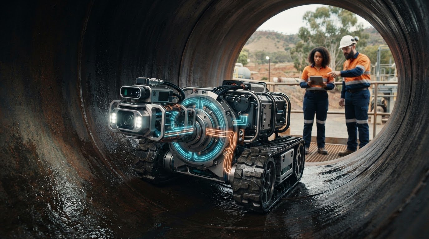
A rotary electrical joint isn’t automatically the right answer for a crawler. First identify which components rotate relative to the main body, then map how data and power for robotic pipe inspection crawler equipment must cross that moving boundary. A tether can connect the crawler to external equipment, but it won’t resolve an internal rotating interface. An onboard supply may reduce cabling, while a rotary connector can maintain electrical paths between stationary and rotating sections.
It’s understandable to focus on camera feeds or motor power first. Reliable selection also depends on the complete load and signal profile, including circuit count, current, voltage, data bandwidth, rotational speed, mounting space and exposure to water or contaminants. Missing one of these requirements can leave the interface poorly matched to the crawler’s operating conditions.
This article explains how to identify rotating assemblies, compare a tether, onboard supply and rotary electrical joint, and build a practical electrical and mechanical specification. It also shows how technical application consulting can help assess Prosper Rotation slip rings against the design requirements.
Key Takeaways
- Trace each electrical path across the crawler to establish whether it crosses a rotating boundary.
- Compare tethered, onboard and rotary-interface arrangements against runtime, cable routing and data-path needs.
- Map data and power for robotic pipe inspection crawler systems by recording circuit count, current, voltage and signal type.
- Include rotational speed, mounting constraints and operating environment in the component specification.
- Use a clear requirements brief to support technical application consulting and a considered rotary connector selection.
Data and power for a robotic pipe inspection crawler: map the electrical architecture first
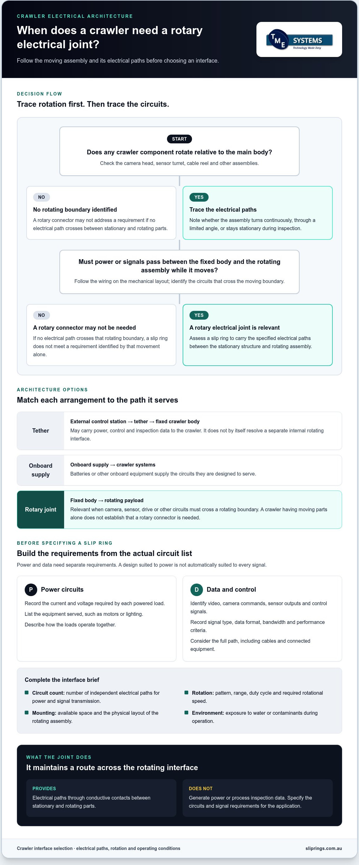
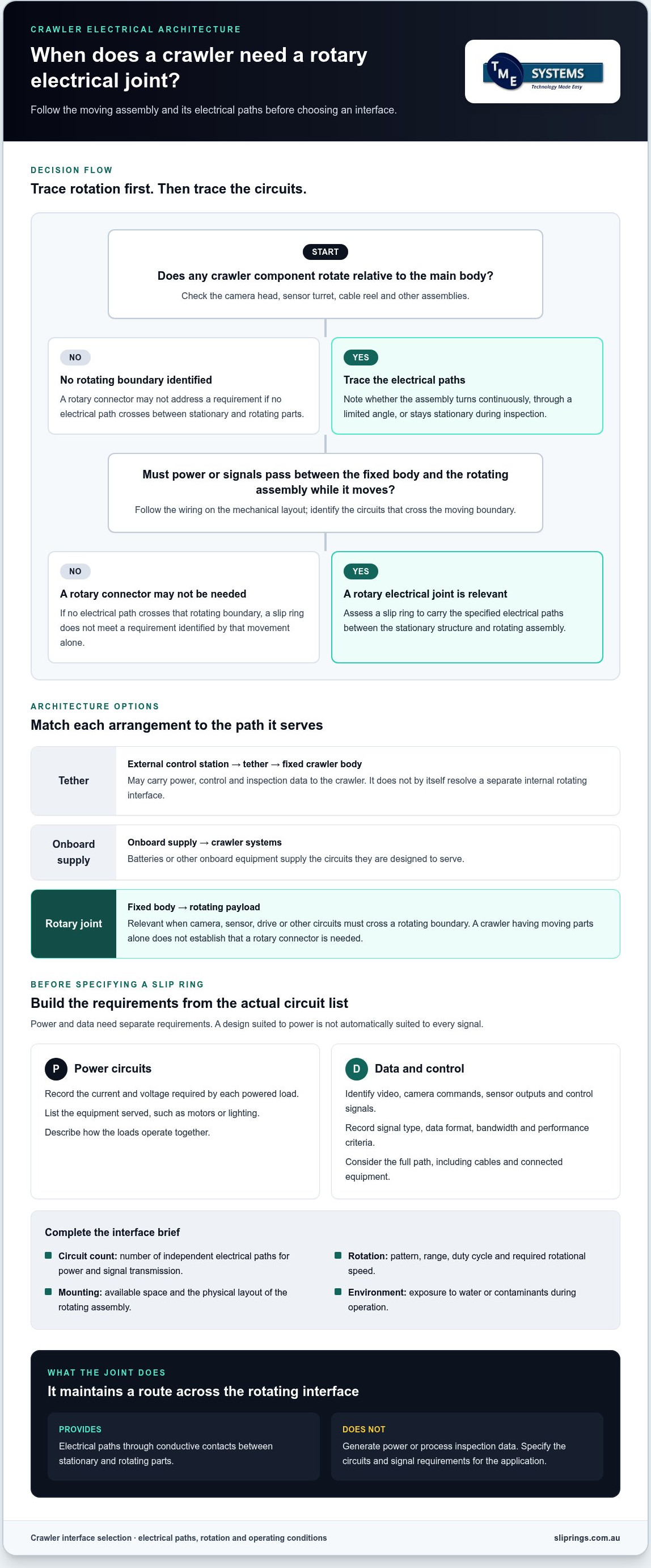
Start by tracing every power and data path through the crawler. The key question isn’t simply whether the machine moves, but whether an electrical connection must cross from a stationary part to a rotating part. A tether may carry power and communications to the crawler body, while a camera head or sensor turret has a separate moving interface to consider. Pipeline video inspection provides context on crawler use; the electrical architecture depends on how the specific crawler is built.
A rotary electrical joint is needed only when power or signals must pass between stationary and rotating components while they move relative to each other. If no electrical path crosses that boundary, a rotary connector may not address a design requirement.
A simplified architecture can help show where to investigate:
- External control station → tether → fixed crawler body: the tether may carry power, control and inspection data.
- Onboard supply → crawler systems: batteries or other onboard equipment supply the circuits they’re designed to serve.
- Fixed body → rotating payload: camera, sensor or drive circuits may need to cross a rotating boundary here.
This is a map, not a prescribed design. Some systems use a tether, some rely on onboard power, and others combine the two. Planning data and power for robotic pipe inspection crawler systems means documenting the actual paths before selecting interface hardware.
Which crawler components rotate during inspection?
Mark the camera head, sensor turret, cable reel and any other assembly that moves relative to the crawler body. Record whether each rotates continuously, turns through a limited angle or stays stationary during inspection. A stationary head has no rotating electrical boundary. Limited-angle motion can have different cable-routing implications from continuous rotation, where a cable crossing the moving boundary can twist without a suitable arrangement.
Follow the wiring on the mechanical layout. If an assembly’s electrical paths cross into the fixed body while it rotates, assess a rotary interface. If they don’t, a slip ring may not be required.
What does the electrical path need to carry?
List loads and signals separately. Depending on the equipment and operating mode, these may include:
- Power: conductors for motors, lighting or other powered equipment.
- Data and control: video, camera commands, sensor outputs and control signals.
Don’t assume every crawler carries the same circuits. Record the actual devices and how they operate together. The circuit count is the number of independent electrical paths a slip ring provides for power and signal transmission. It’s a useful starting point for describing the interface, but doesn’t replace specifying each path’s electrical and signal requirements.
How a rotary electrical joint transfers crawler power and inspection data
A slip ring carries electrical circuits between a stationary structure and a rotating assembly. Its stationary and rotating parts connect through conductive contacts, allowing the assembly to turn while electrical paths remain connected. The connector doesn’t generate power or process inspection data; it provides a route for specified circuits across the rotating interface.
Power circuits deliver energy to loads; signal circuits carry video, control commands or sensor data, and each needs requirements suited to its function. Both can pass through a rotary electrical joint, but a design that works for power isn’t automatically suitable for every signal.
When is a tether enough, and when is a rotary connector relevant?
A tether may carry power and communications from the control station to the crawler when it ends at a stationary body and no circuits cross an internal rotating boundary. A rotary connector becomes relevant if those circuits must continue into a rotating head, turret or other assembly.
Rotation changes the cable’s mechanical conditions. Repeated or continuous movement can twist a cable, alter its routing or place extra load on terminations. Whether a fixed cable arrangement is suitable depends on rotation range, duty cycle and physical layout. Trace the full cable route through the expected movement before deciding; a crawler having moving parts alone doesn’t mean it needs a rotary connector.
How should engineers think about power and data together?
Begin with the individual circuits, not a single combined power-and-data rating. Record the voltage and current required by each powered load, then identify each signal and its transmission requirements. A camera’s video feed, an Ethernet connection, control signals and sensor outputs can have different electrical characteristics.
High‑speed data transmission depends on the signal type and system design. A rotary interface must suit the required bandwidth and signal integrity, but those outcomes shouldn’t be assumed from the connector category alone. Document the data format, operating conditions and performance criteria for the full path, including cables and connected equipment.
For a practical design review, bring together the rotation pattern, circuit list and electrical requirements before comparing connector options. TME Systems supplies Prosper Rotation slip rings and provides technical application consulting to assess them against the crawler’s requirements.
Compare crawler power and data architectures before specifying a slip ring
Choose the architecture by tracing where energy and signals originate, where they need to go, and which parts move during inspection. A tether, onboard supply and rotary electrical joint solve different parts of the problem. A joint transfers circuits across a rotating boundary; it doesn’t replace the crawler’s power source or determine how the system communicates with its operator.
| Architecture | Rotation | Runtime dependency | Cable routing and data path |
|---|---|---|---|
| Fixed tether | Suitable where the tether terminates at a stationary crawler section. Movement of the tethered assembly must be considered. | Depends on the external supply and operating arrangement. | Routes power and data along the tether. A tether alone doesn’t carry circuits across an internal rotating boundary. |
| Onboard supply | Can supply moving components without a power tether crossing their rotating interface. | Depends on onboard capacity and operating conditions. Establish runtime from the actual design. | Reduces reliance on a power path from the surface, but data still needs a defined route to and from the crawler. |
| Rotary electrical joint | Relevant where electrical paths must continue between stationary and rotating sections. | Doesn’t set runtime. That depends on the power source and system operation. | Transfers specified power or signal circuits across the rotating interface. External communications may still use a tether or another data path. |
What changes between tethered and onboard power?
A tether gives the crawler a physical route to external power and communications, but the cable needs room to move and a clear path through the inspection setup. Consider how it bends, where it connects and whether movement could pull on the cable or terminations. An onboard supply changes that arrangement, not the need to define capacity, operating duration and signal paths. Don’t assign runtime figures without data for the crawler’s actual loads and operating mode.
When does a slip ring become the practical interface?
Consider a slip ring when circuits must cross a continuously rotating boundary and a fixed cable would twist or restrict the required movement. Assess circuit count, mounting geometry and operating conditions together. Available space and the position of the rotating shaft can influence mounting options, while the electrical and data requirements shape the circuits to be transferred.
For selection context, review Prosper Rotation slip rings alongside the crawler’s requirements. A considered architecture for data and power for robotic pipe inspection crawler systems starts with the motion, supply and data route, then matches the rotary interface to those requirements.
Build a crawler slip ring specification from measurable requirements
A useful specification turns the crawler layout into information that can be assessed against a rotary connector’s electrical, mechanical and environmental requirements. Separate measured or documented values from assumptions, and identify open items for engineering review. This gives component selection a clear basis rather than relying on a broad description of the crawler’s intended use.
Which electrical and signal details should the specification capture?
List each circuit and its role. Record the operating requirements for each power load separately from those for video, communications, control and sensor signals. Circuit count means the number of independent electrical paths required through the interface.
- Inventory the circuits. Identify the connected equipment and whether each path carries power, data or control.
- Record electrical demands. For every powered load, note voltage, current and duty requirements. Include operating conditions that may affect the load.
- Describe signal requirements. State the data protocol and required bandwidth for each signal, based on the crawler system design. Don’t assume a connector suitable for one signal type will support another.
- Mark uncertainty. Label values as confirmed, estimated or awaiting engineering review. This prevents an assumption from being mistaken for a final requirement.
Which mechanical and environmental details affect selection?
Give the interface a physical context. Include shaft dimensions or other mounting geometry, available space, cable-entry direction and clearance constraints. State whether rotation is continuous or limited, and specify the required rotational speed rating from the actual motion profile.
- Describe movement and mounting. Provide the rotation pattern, speed requirement and drawings or measurements of the intended mounting location.
- Define the operating environment. Record relevant exposure to dust, water, vibration and temperature. Assess the required IP rating against the actual ingress risk rather than selecting a rating in isolation.
- Consider heat in context. Where operating current, ambient temperature or duty could affect temperature rise, include thermal management requirements for assessment.
These factors interact. The mounting arrangement must fit the crawler while leaving a practical route for wiring, and operating conditions can affect how electrical requirements are assessed. Avoid assigning limits without design evidence.
For data and power for robotic pipe inspection crawler applications, a structured brief connects the circuit list to speed, mounting and environment. TME Systems provides technical application consulting to support selection against these requirements. Discuss your slip ring application with the specification details ready.
From crawler requirements to a considered rotary connector selection
A requirements table becomes a useful component-selection brief when it connects each electrical path to the crawler’s movement, physical layout and operating environment. TME Systems’ technical application consulting considers circuit count, current, voltage, speed, mounting and environmental requirements to support selection. Assess the interface as part of the system rather than choosing a connector based on one specification in isolation.
What information makes an engineering review useful?
Bring together the information that describes both the electrical load and the space the rotary connector must fit. A system diagram is a useful starting point, especially if it shows the stationary and rotating sections and where each circuit crosses between them.
- Electrical and signal details: list each circuit’s purpose, voltage, current, duty requirements, signal protocol and bandwidth needs.
- Mechanical information: provide mounting dimensions, shaft or interface geometry, available clearance and cable-entry direction.
- Motion profile: describe whether rotation is continuous or limited, along with the required speed and expected duty.
- Operating environment: document relevant exposure to dust, water, vibration and temperature.
- Open items: mark estimated values, unresolved requirements and assumptions that need engineering review.
Separating confirmed values from unknowns helps focus the review. It also prevents a preliminary assumption, such as a signal protocol or ingress requirement, from being treated as a final design input.
How can the connector choice support inspection reliability?
A suitable rotary electrical connector must maintain the required electrical paths while fitting the mechanical arrangement and carrying the specified signals. Selection should account for the complete circuit set, not just the motor supply: video, control and sensor paths can have different requirements. Physical integration matters too. A connector that meets electrical needs still has to suit the mounting position and cable route.
These checks help engineers assess continuity and signal requirements against the actual design. They don’t establish an unverified service life, compliance status or performance outcome. TME Systems supplies Prosper Rotation slip rings and can provide technical application consulting to assess the range against your application requirements.
Share your application requirements with TME Systems for technical guidance on selection. A system diagram, circuit schedule, motion profile and mounting dimensions provide a practical basis for discussing a rotary connector for your crawler.
Turn crawler requirements into a clear interface decision
Start with the rotating boundary: a rotary electrical joint is relevant only if power or data paths must cross between stationary and rotating components. Then compare tethered, onboard and rotary-interface arrangements against the crawler’s movement, cable routing and data-path needs.
A practical specification records each circuit’s purpose and electrical demands alongside signal requirements, rotation, mounting geometry and operating environment. This gives component selection a sound basis. TME Systems’ technical application consulting considers these electrical, mechanical and environmental factors to help refine a suitable selection. If AS/NZS 5368:2025 is relevant to the project, establish its scope and applicability before treating it as a design or compliance criterion.
Bring your circuit details, system layout and operating conditions together, then discuss your crawler’s rotary connection requirements with TME Systems. A well-defined interface brief is a practical next step towards a considered connector choice.
Frequently Asked Questions
Does a robotic pipe inspection crawler always need a slip ring?
No. A crawler needs a slip ring only if an electrical path must cross between stationary and rotating sections during movement. If its inspection head stays stationary, or the cable arrangement serves the required movement without crossing a rotating boundary, a rotary connector may not be needed. Map camera heads, sensor turrets, reels and other moving assemblies, then trace their power and signal paths before choosing an interface.
How does a slip ring transfer data and power at the same time?
A slip ring maintains electrical paths between stationary and rotating parts through conductive contacts as the assembly turns. Separate circuits can carry power to loads and signals between equipment, provided the connector is specified for those requirements. It doesn’t generate power or process data. Circuit count, electrical load and signal characteristics all matter, so assess each path rather than assuming one general rating covers the complete interface.
Can Ethernet or video signals pass through a crawler slip ring?
They can if the rotary interface is suited to the signal type and system requirements. Ethernet and video paths have specific bandwidth and signal integrity needs, so compatibility shouldn’t be assumed from the fact that a connector transfers power. Record the protocol, required data rate and relevant operating conditions, then assess the complete transmission path, including the slip ring, cabling and connected equipment.
What information is needed to specify a slip ring for a pipe crawler?
A specification for data and power for robotic pipe inspection crawler systems should identify each circuit’s purpose, voltage, current, duty and signal type. Include circuit count, data protocols, bandwidth, rotation pattern and required rotational speed rating. Add mounting geometry, available space, cable-entry direction and operating conditions such as dust, water, vibration and temperature. Mark assumptions separately from confirmed values so they can be addressed during engineering review.
Is a tether or onboard battery better for a pipe inspection crawler?
Neither is universally better. A tether can provide a route for power and communications to the crawler, but its movement, routing and connection points need consideration. An onboard battery changes the power arrangement, while capacity and operating duration remain design factors; data still needs a defined path. Compare the options against the crawler’s layout, movement, required operating period and communication needs rather than choosing by architecture alone.
What environmental factors affect a crawler rotary electrical connector?
Assess the actual exposure to water, dust, vibration and temperature around the connector. These conditions can affect enclosure and mounting requirements, while operating current and ambient temperature may also make thermal management relevant. Specify the required IP rating against the expected ingress exposure, not simply the most protective rating available. Include operating conditions in the application brief so the connector can be assessed as part of the complete installation.
When should an engineer involve slip ring application consulting?
Involve application consulting when defining the interface, comparing architectures or translating crawler requirements into a component-selection brief. It’s particularly useful where power and signal circuits share a rotating interface, mounting space is constrained, or environmental conditions affect selection. TME Systems’ technical application consulting considers circuit count, current, voltage, speed, mounting and environmental requirements to support a considered choice. Provide a system diagram and note any unresolved design assumptions.