What if the rotary connection is where a fault becomes visible, but not where it starts? Intermittent dropouts can disappear during a stationary check, then return with rotation, vibration, load or temperature changes. That makes diagnosing intermittent data loss in rotating systems difficult: the symptom may point to a slip ring, while the cause lies in the signal source, wiring, operating conditions or rotary connection.
Replacing the connector first may leave the original fault untouched. A more reliable approach is to trace the complete signal path under real operating conditions. Record when dropouts occur, which channels are affected, and the relevant rotation, load and environmental conditions.
This guide sets out a repeatable sequence to help distinguish signal, wiring, mechanical and rotary connection issues before changing hardware. You’ll learn what measurements and operating details to capture, how to assess connector technology against your findings, and when technical application consulting may help clarify requirements. The evidence can also help determine whether options such as liquid metal rotary connectors warrant further assessment.
Key Takeaways
- Trace the signal from source to receiver, changing one test condition at a time.
- When diagnosing intermittent data loss in rotating systems, distinguish clues from the connector interface, cabling, terminations, signal compatibility and external interference.
- Build a test record that captures the system configuration, operating state and result for each check.
- Use the evidence to decide whether to retain the connector, investigate another part of the signal path or review connector selection.
- Match any connector review to documented signal, circuit, speed, mounting and environmental requirements.
What intermittent data loss in rotating systems looks like and what to record first
Intermittent data loss in a rotating system is a sporadic interruption, corruption or absence of information as signals pass through rotating equipment. It describes a symptom, not a confirmed fault in the rotary connector. The cause could be at the signal source, along the wiring path, at a termination, in the operating environment or at the rotating interface. Start by documenting what happens before changing components.
A slip ring transfers electrical power or signals between stationary and rotating structures. Understanding where it sits in the complete path helps frame the investigation. Wikipedia provides an overview of electromechanical slip rings. The key is to distinguish where data disappears from the part responsible for the problem.
Which symptoms help narrow down a rotating system data fault?
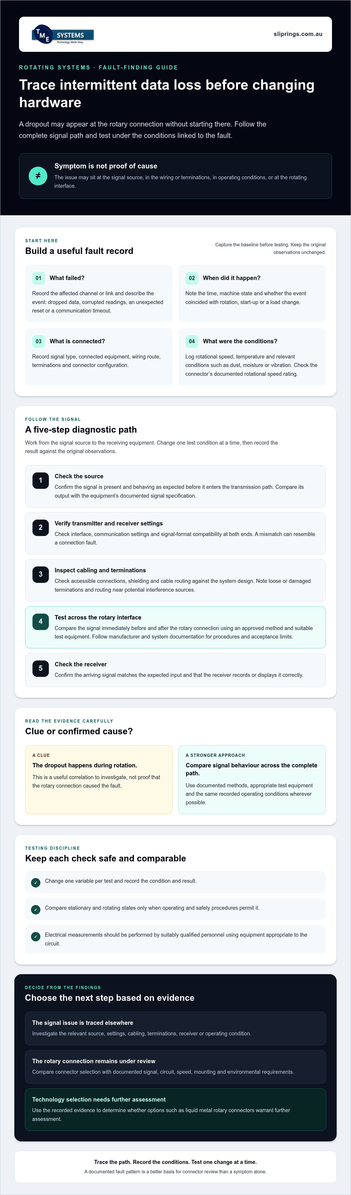
Describe the event precisely. A dropped data packet, a corrupted reading, an unexpected equipment reset and a communication timeout are different observations, even if they occur together. Record whether one channel is affected, several channels fail or the full link goes offline. Note whether the event coincides with rotation, start-up, a load change or a particular machine state. These patterns help direct later tests, but they don’t establish the cause on their own.
What evidence should be collected before testing?
Build a baseline while the system is operating normally. Record the signal type, connected equipment, wiring route, terminations and connector configuration. For each fault, include the operating state and timestamp, along with rotational speed, temperature and relevant environmental conditions such as dust, moisture or vibration. Check the connector’s rotational speed rating in its documentation and compare it with operating conditions. Keep observations factual: a fault occurring during rotation is a useful correlation, not proof that the connector caused it.
- Channel and data: Identify the affected channel or link and the type of interruption or corruption.
- Timing and state: Note when the fault occurs and what the equipment is doing.
- Configuration: Record signal type, connected devices, wiring route and connector details.
- Conditions: Log speed, temperature and relevant environmental observations.
This record gives diagnosing intermittent data loss in rotating systems a sound starting point. Keep the original observations unchanged so later tests can be compared with the same baseline.
How to diagnose intermittent data loss in rotating systems across the signal path
Follow the signal in order, from its origin to the receiving equipment. This keeps the investigation focused on evidence rather than assumptions about the rotary connection. The sequence below helps you diagnose intermittent data loss in rotating systems without changing several variables at once.
- 1. Check the source. Confirm that the signal is present and behaving as expected before it enters the transmission path. Compare the source output with the equipment’s documented signal specification.
- 2. Verify transmitter and receiver settings. Check that interfaces, communication settings and signal formats are compatible at both ends. A mismatch can resemble a connection fault.
- 3. Inspect the cabling and terminations. Check accessible connections, shielding and cable routing against the system design. Look for loose or damaged terminations, and note routing changes near potential sources of interference.
- 4. Test across the rotary interface. Compare the signal immediately before and after the rotary connection using an approved method and suitable test equipment. Follow manufacturer and system documentation for measurement procedures and acceptance limits.
- 5. Check the receiver. Confirm that the signal arriving at the receiver matches the expected input and that the receiver records or displays it correctly.
Make one change per test, then record the condition and result against the original fault observations. If the equipment can be tested safely in both stationary and rotating states, compare the results. Don’t run either test if the equipment’s operating and safety procedures don’t permit it. Electrical measurements should be performed by suitably qualified personnel using equipment appropriate to the circuit.
How can wiring, terminations and signal settings be checked?
Inspect accessible wiring and connections, then compare them with the approved design. Verify that the transmitter, receiver and interface settings agree with the specified signal type. Avoid changing shielding, routing or settings during the same test. If the behaviour changes, this approach helps identify which alteration may be relevant.
How should faults be correlated with rotation and operating conditions?
Compare fault timestamps with recorded rotational speed, direction, load, equipment state and temperature. Note relevant environmental changes too. Research into fault diagnosis in rotating machinery illustrates the value of structured observations. A pattern in your own records still needs repeatable testing before it supports a cause.
Repeated dropouts at a similar operating state can help narrow the next test, but timing alone doesn’t prove the rotary connection is responsible. If testing points to connector selection, compare documented signal and operating requirements with options such as Prosper Rotation slip rings, or seek technical application consulting to assess suitability.
How to separate connector faults from signal and operating condition problems
A dropout at the receiver doesn’t identify its source. Compare the clues with evidence from each part of the signal path before treating the rotary connection as the cause. This table can help direct the next check.
| Possible source | Clues to assess | Next evidence to collect |
|---|---|---|
| Signal compatibility | Dropouts or corrupted readings occur when the system is stationary, or follow a change in interface settings. | Compare the signal specification and transmitter, receiver and interface settings with the equipment documentation. |
| Cabling and terminations | Faults vary after cable movement or are localised to particular conductors or connections. | Inspect accessible wiring, shielding, routing and terminations against the approved design. Record any defect without disturbing other test conditions. |
| External interference | Events coincide with other equipment switching or operating, or with changes to the cable route or environment. | Record nearby equipment states and compare fault timing. Check cable routing and shielding against system guidance. |
| Rotary connector interface | Faults repeatedly occur during rotation or at a similar mechanical position, while the upstream signal remains stable. | Compare measurements before and after the interface under safe, repeatable conditions. Review connector condition and installation against manufacturer guidance. |
| Operating conditions | Faults track with changes in speed, load, temperature or machine state, but not consistently with one connector position. | Correlate timestamps with operating records and repeat tests while changing one condition at a time. |
Which clues point to a rotary electrical connection?
A repeatable relationship with rotation or a particular mechanical position makes the connector interface a stronger hypothesis, not a confirmed cause. Check its installation and condition against the manufacturer’s instructions. Then compare the installed circuit count and signal requirements with the equipment specification. Don’t assume that a visible mark or a single failed test establishes the root cause.
When should liquid metal rotary connectors be considered?
Liquid metal rotary connectors are brushless rotary connectors that use a pool of conductive liquid metal to maintain electrical continuity, eliminating wear and reducing noise. This is one contact method to assess, not a universal remedy for data loss. Consider it only against documented signal, operating and environmental requirements, and check applicable limits in manufacturer documentation. The Mercotac slip rings page is a category reference, not evidence that a particular connector will resolve the fault.
For a broader selection review, organise the recorded evidence alongside circuit count, current, voltage, speed, mounting and environmental requirements. Technical application consulting can help assess connector selection against those documented needs. When diagnosing intermittent data loss in rotating systems, let the evidence guide the technology choice rather than using it as a substitute for investigation.
A practical test plan for confirming intermittent data loss
A repeatable test plan turns intermittent events into comparable evidence. Keep the original fault record as your baseline, then work through each stage without changing several conditions at once. For every check, note the date and time, configuration, measurement method, equipment state and result, including when the fault doesn’t occur.
How can testing be made repeatable?
Use the same configuration and documented measurement method for each comparison. Record both normal and fault conditions, including relevant machine states. If a test requires a setting or component change, document it and make only that change before repeating the check. Follow equipment documentation for measurement methods and acceptance limits. Before interpreting a result outside a specified limit, confirm that you used the correct procedure and test conditions.
- Baseline: Capture the reported symptom, affected channel or link, current configuration and normal operating state. Include existing fault records and timestamps.
- Visual inspection: Check accessible wiring, terminations, connector installation and surrounding conditions against approved drawings and manufacturer instructions. Record observations. Don’t dismantle or adjust equipment during a visual check unless authorised procedures permit it.
- Controlled test: Under safe operating conditions, compare normal and fault states using the same measurement method. Note speed, load, direction or other relevant machine states, and change one test condition at a time.
- Evidence review: Compare results with the baseline. Separate confirmed observations from possible explanations, and flag missing data or measurements that need verification.
These are diagnostic checks, not instructions to carry out corrective electrical or mechanical work. Measurements and changes involving exposure to hazards, altered wiring or equipment operation should be left to qualified personnel working to relevant procedures and manufacturer guidance.
What should be included in a diagnostic handover?
Prepare a concise record that another engineer or application specialist can assess without reconstructing the test. Include the signal type, circuit count, voltage, current and operating speed where known. Add the connector configuration and mounting arrangement, wiring route and termination details, environmental conditions, fault timestamps, test method and results for both normal and fault states. Mark unknown values clearly rather than estimating them.
This evidence can support a focused selection review if the findings point towards the rotary connection. TME Systems offers technical application consulting to help assess documented connector requirements, including circuit count, current, voltage, speed, mounting and environmental conditions.
Choosing the next step after diagnosing rotating system data loss
Use the evidence to decide what to investigate next rather than replacing parts by default. If repeatable tests show the signal remains stable through the rotary interface, retain the connector as the current working choice and continue checking other signal path elements. If the fault is linked to a cable, termination, signal setting or operating condition, investigate that part of the system. If findings point to the connector, compare its documented specification with the application before considering a change.
When is a connector specification review warranted?
A review is appropriate when the installed configuration appears inconsistent with documented requirements, or when repeatable tests isolate the rotary interface as a likely source. Check that the signal type and circuit count suit the system, then compare the required electrical ratings, rotational speed rating and mounting arrangement with the installed connector’s documentation. Consider environmental conditions too. Confirm product suitability against the relevant manufacturer information before recommending a different connector or contact technology.
Keep the decision proportionate to the evidence:
- Retain the connector when results don’t implicate the rotary interface and its documented specifications match the application.
- Investigate elsewhere when evidence points to the source, receiver, cabling, terminations, settings or operating conditions.
- Review connector selection when the interface is implicated or its specifications don’t align with the recorded requirements.
What information helps an application consultation?
Bring the diagnostic log, including the conditions under which faults appear and the tests that did not reproduce them. Summarise the system’s function and connection layout, then provide known signal, circuit count, voltage, current, operating speed, mounting and environmental requirements. Note uncertainties clearly. This helps keep a selection discussion grounded in the application rather than assumptions based on the symptom alone.
Diagnosing intermittent data loss in rotating systems may show that a connector review is useful, but it doesn’t mean one technology will resolve every fault. TME Systems supplies industrial slip rings and rotary electrical connectors to Australian customers, with technical application consulting to help assess connector selection against documented requirements.
Turn your fault records into a clear next step
Reliable diagnosing intermittent data loss in rotating systems starts with evidence, not an assumption that the rotary connector is at fault. Trace the signal path from source to receiver, record the conditions around each event and compare test results while changing one condition at a time. This helps distinguish a connector issue from problems with cabling, terminations, signal compatibility or machine operation.
Use the findings to decide whether to retain the installed connector, investigate another part of the system or review selection. If a review is warranted, compare the application’s signal, circuit count, electrical requirements, speed, mounting and environment with the connector’s documented specifications.
TME Systems supplies industrial slip rings and rotary electrical connectors to Australian customers, with technical application consulting for connector selection. Share your diagnostic log and known application requirements to support a focused discussion about suitable options.
Discuss your rotary connector application with TME Systems. A methodical investigation gives you a sound basis for the next decision.
Frequently Asked Questions
What causes intermittent data loss in a rotating system?
Intermittent data loss can originate anywhere along the signal path, not just at the rotary connector. Possible causes include an unstable source, incompatible signal settings, loose terminations, damaged or poorly routed cabling, external interference, or connector issues associated with operating conditions. Vibration, contamination or wear may also affect a connection. When diagnosing intermittent data loss in rotating systems, treat each possibility as a hypothesis and compare it with repeatable observations.
How do you test a slip ring for intermittent signal faults?
Trace the signal from source to receiver and compare it before and after the slip ring using a suitable, documented measurement method. Record results in normal and fault conditions, including the machine state and relevant operating conditions. Compare stationary and rotating behaviour only if the equipment can be tested safely in both states. Qualified personnel should perform electrical measurements, following system and manufacturer documentation for procedures and acceptance limits.
Can a slip ring cause data dropouts only at certain speeds?
Yes, a dropout may appear at particular speeds, but that pattern alone doesn’t confirm a slip ring fault. Speed may coincide with changes in vibration, load, temperature or another machine state. Record the speed and conditions at each event, then repeat controlled comparisons where safe, changing one factor at a time. Check the connector’s rotational speed rating and operating limits against the relevant manufacturer documentation before drawing a conclusion.
How can I tell whether data loss comes from wiring or a rotary connector?
Compare the signal at points along the path, including before and after the rotary interface, using an appropriate test method. Inspect accessible wiring, shielding and terminations against the system design. If the signal is already unstable upstream, investigate the source or wiring first. If it remains stable before the connector but changes across it during repeatable rotation tests, the interface warrants closer assessment. Neither clue alone proves the root cause.
Can liquid metal rotary connectors reduce intermittent data problems?
They may suit some applications, but they aren’t a universal remedy for intermittent data loss. Liquid metal rotary connectors are brushless rotary connectors that use a pool of conductive liquid metal to maintain electrical continuity, eliminating wear and reducing noise. Assess this contact method against the documented signal, operating and environmental requirements. Confirm product suitability and limits with manufacturer documentation, and rule out faults elsewhere in the signal path before considering a change.
What information should I collect before asking for slip ring application advice?
Prepare a diagnostic log with fault timestamps, affected channels, test conditions and observed results. Add the signal type, circuit count, voltage, current and operating speed where known, plus the connector configuration, mounting arrangement, wiring route and environmental conditions. Mark unknown details rather than estimating them. This information helps TME Systems’ technical application consulting assess connector selection for Australian applications and gives diagnosing intermittent data loss in rotating systems a specification-led next step.
When should a rotary connector be replaced rather than further tested?
Consider replacement when documented evidence identifies the connector as the fault source, or when its verified specifications don’t meet the application’s requirements. First compare test findings and operating conditions with manufacturer guidance, including any relevant acceptance criteria. A recurring dropout by itself isn’t enough to justify replacement, since wiring, signal compatibility or external conditions may be responsible. Have qualified personnel assess any corrective work that involves electrical or mechanical hazards.