What makes a premium contact material the right engineering choice? In a rotary connector, a material decision is justified when operating evidence shows that it addresses a defined risk or performance requirement. That’s the basis of an engineering justification for premium contact materials, not a label or supplier claim.
It’s reasonable to scrutinise material claims. An unsuitable contact choice can affect signal integrity, wear and maintenance planning, while an over-specified material may add complexity without meeting a measurable need. The decision should reflect the conditions the connector will actually face.
This article explains how to build a defensible rationale from application requirements and verifiable performance evidence. Compare electrical loads, signal types, rotational speed, duty cycle, mounting constraints and environmental conditions with test results from relevant operating conditions. Assess what the evidence shows about contact resistance, signal behaviour, wear and temperature rise, and note where it doesn’t match the application. TME Systems’ technical application consulting helps connect these requirements with rotary connector selection and prepare a concise engineering brief for final application review.
Key Takeaways
- Define what “premium” must achieve in your application. It isn’t automatically the better choice.
- Assess contact resistance and continuity alongside signal integrity, wear and service requirements.
- Compare material options only when product data and test conditions are equivalent.
- Build an engineering justification for premium contact materials by linking each specification choice to a defined requirement and supporting evidence.
- Use a clear application brief to guide connector selection and identify trade-offs that need final engineering review.
When does engineering justify premium contact materials in a rotary connector?
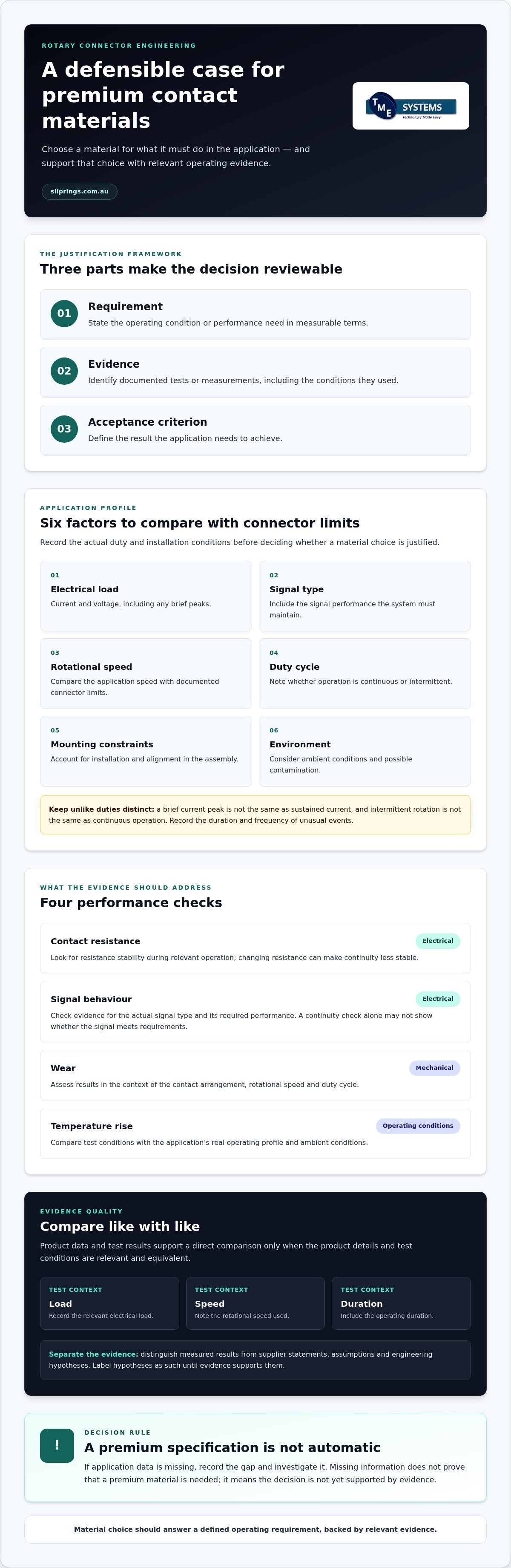
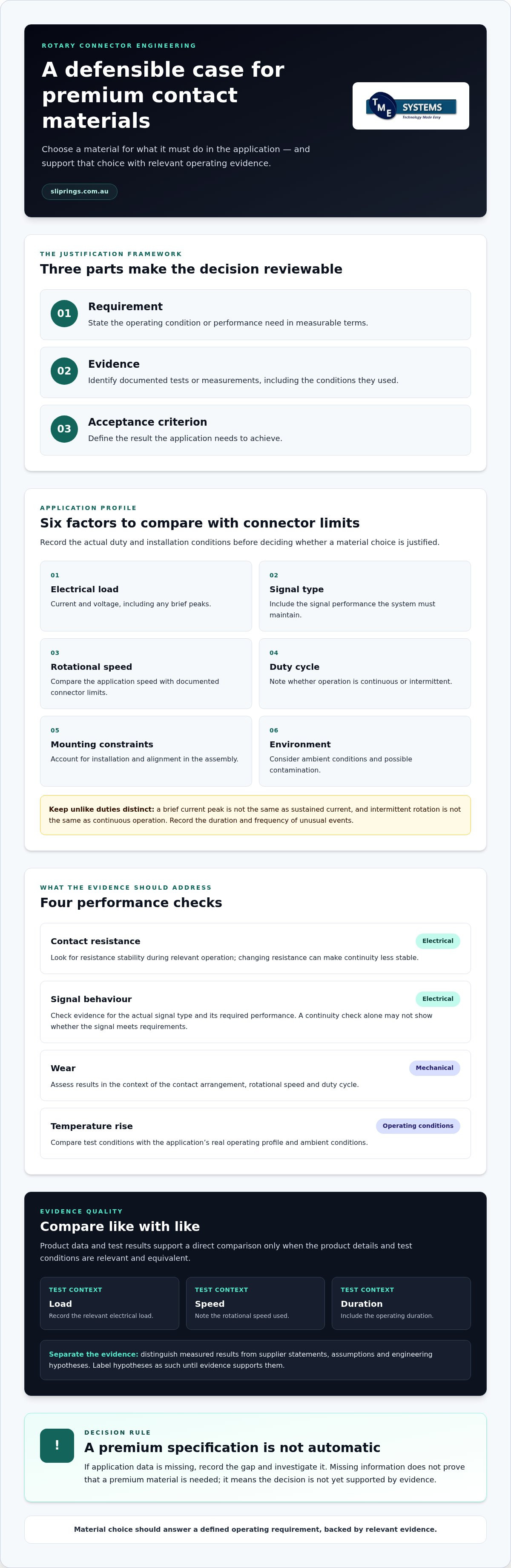
A higher-grade contact material is justified when it addresses a defined operating requirement. An engineering justification for premium contact materials documents the link between the application’s demands, the contact performance required and evidence that the selected option can meet them. “Premium” describes a specification choice, not automatic superiority in every rotary connector.
Assess the material alongside the connector architecture, installation and operating profile. A slip ring transfers power or signals between stationary and rotating parts, as outlined in Slip ring (Wikipedia). Contact material is one part of the design. Circuit arrangement, mounting, alignment, ambient conditions and equipment operation also affect whether the assembly suits the application.
Which application demands can make material choice consequential?
Start with the actual duty: current, voltage, signal type, rotational speed and duty cycle. Record each requirement in measurable terms, then compare it with the selected connector’s documented limits. Include whether power and signal circuits operate together, and whether the equipment runs continuously or for short periods.
That distinction matters. A brief current peak is not the same demand as sustained current, and intermittent rotation differs from continuous operation. Document the duration and frequency of unusual events rather than treating them as normal duty or ignoring them. A mismatch between the application profile and the connector’s stated limits is a reason to review the selection, not proof that a premium material is required.
What does a defensible material justification contain?
Build the rationale around three items: the operational requirement, the evidence supporting the proposed choice and the acceptance criterion. For example, define the signal behaviour the system must maintain, identify test results relevant to that signal and state what result would be acceptable. This gives reviewers a practical basis for assessing the specification.
Separate measured results from supplier statements, assumptions and engineering hypotheses. Record test conditions, including relevant load, speed and operating duration, so results can be judged against the real application. A performance claim without its test context may not support a direct comparison. Label a hypothesis about expected material behaviour as such until evidence supports it.
- Requirement: State the operating condition or performance need.
- Evidence: Identify the documented test or measurement and its conditions.
- Acceptance criterion: Define the result the application must achieve.
If current, signal behaviour or operating duty is unknown, record the gap and investigate it. Missing application data doesn’t make a premium specification necessary. It means the material decision is not yet supported. This approach keeps selection tied to operating evidence while making connector architecture and installation conditions visible in the wider engineering review.
How do contact materials affect electrical performance, wear and service requirements?
Contact material influences the electrical path between stationary and rotating parts, but it doesn’t determine performance on its own. Contact resistance describes opposition to current flow at the interface. If resistance varies during rotation, electrical continuity can become less stable. In signal circuits, that variation may affect signal integrity, so a continuity check alone may not show whether the transmitted signal meets application requirements.
Material comparisons need product-specific data. A result from one contact arrangement or operating profile can’t automatically be applied to another. Review resistance stability, signal behaviour and wear evidence under conditions relevant to the intended connector and duty. Avoid ranking materials in isolation. The practical question is whether a documented option meets the application’s electrical and mechanical needs.
Which electrical and mechanical performance measures matter?
For electrical performance, look for evidence on resistance during operation and the behaviour of each signal type. For mechanical performance, consider wear alongside the contact arrangement, rotational speed rating and duty cycle. A connector operating continuously may experience a different wear profile from one that rotates intermittently. Service implications depend on this complete operating pattern, not on the material name alone.
- Resistance stability: Does the evidence show consistent contact behaviour during relevant operation?
- Signal behaviour: Does testing address the signal type and its required performance?
- Wear evidence: Were the contact arrangement, speed and duty relevant to the application?
How do operating conditions change the material decision?
Ambient conditions, contamination and installation all affect the operating environment. Where temperature changes matter, account for thermal expansion, the increase in a material’s size due to heat, and assess whether it could affect the assembly at its operating speed. Consider contamination in relation to the contact design and the conditions documented for the selected connector.
Thermal management, the techniques used to control temperature rise in a slip ring during operation, belongs in the system-level assessment. Current, operating duration, ambient temperature and installation all contribute to the thermal picture. Thermal derating, the reduction of allowable current based on increased ambient temperature to prevent overheating, may therefore affect the allowable operating load. Assess it against product documentation rather than assuming a material upgrade will resolve a thermal issue.
An IP rating defines the level of protection against dust and water ingress for electrical equipment. Use it when ingress is a defined application requirement, and compare the stated rating with product evidence and the actual environment. It doesn’t establish contact performance under every condition.
These measures turn material claims into a technical review of the whole connector. TME Systems’ technical application consulting supports evaluation of electrical, speed, mounting and environmental requirements alongside contact evidence.
How should engineers compare premium and standard contact-material options?
A fair comparison starts with the application, not the material label. Set out the electrical duty, operating profile and environment, then compare options using product data gathered under equivalent test conditions. If one result was measured at a different speed, load or duration, it may not support a direct performance ranking. The aim is to identify which option meets the requirement and what evidence supports that conclusion.
Keep contact material separate from other design variables. Circuit count, connector architecture, mounting and installation can each affect performance. If the compared connectors differ in these respects, a difference in test results can’t be attributed to material alone. Record those variables so the comparison remains technically meaningful.
Which criteria belong in a material comparison?
Use a consistent comparison record. For every performance claim, note its source, test conditions and limitations. Include electrical requirements, expected operating profile, environmental exposure, maintenance needs and how performance will be verified in the application. Where evidence is incomplete, mark the question as unresolved rather than treating an assumption as a proven advantage.
Application requirement: Record the circuit duty, signals, operating pattern and environmental conditions that matter.
Evidence: Identify product-specific test data, its source and the conditions under which it was obtained.
Trade-off: Note relevant differences in contact method, connector design and maintainability without assuming a service-life or maintenance benefit.
Unresolved question: Flag missing data or differences that prevent a fair comparison.
This format makes the engineering justification for premium contact materials traceable. It also shows reviewers whether a claimed benefit is measured, inferred or still needs investigation. Don’t assign a material advantage where available data can’t distinguish it from a change in circuit arrangement, installation or operating conditions.
When might a liquid-metal contact approach be considered?
Liquid metal rotary connectors are brushless rotary connectors that use a pool of conductive liquid metal to maintain electrical continuity, eliminating wear and reducing noise. This describes the contact approach, not an automatic fit for every duty. Compare it with other contact methods against the application’s electrical, mechanical and environmental requirements. Product-specific evidence remains essential.
For a liquid metal design, include material compatibility and operating exposure in the review. Gallium-based alloys can change over time through thermal cycling and oxidation, and untreated copper alloys may be susceptible to attack. These are reasons to examine material compatibility and relevant product evidence, not to assume every design behaves the same way. TME Systems supplies Mercotac slip rings, including liquid metal rotary connectors, for consideration in this comparison.
For a connector selection discussion grounded in application requirements, TME Systems’ technical application consulting can relate contact-method trade-offs to the wider specification.
How can you validate the engineering case before specifying a material?
Validate the decision before it becomes a fixed specification. A clear review moves from the machine’s operating requirements to relevant evidence, then records what the chosen contact must achieve. This makes the engineering justification for premium contact materials traceable and helps prevent a material preference from becoming a requirement without supporting data.
What information should the engineering review capture?
Prepare an application brief that describes the complete duty, not just the electrical load. Include circuit count, current, voltage, signal type, operating profile, rotational speed, mounting style and environmental requirements. Note known performance concerns or failure modes, and distinguish routine operation from exceptional events.
Mark each requirement according to its evidence status: supported by product documentation or test data, based on an assumption, or still requiring evaluation. This helps reviewers focus on genuine information gaps rather than treating every unknown as a reason to specify a higher-grade material.
How should evidence be tested and documented?
Use a staged review so the specification follows the evidence:
- Define the duty. Write down the operating conditions the connector must handle, including relevant load, speed, signal and environment.
- Set acceptance criteria. Decide in advance how the required electrical or mechanical performance will be measured and what result will be acceptable.
- Review comparable evidence. Compare candidate configurations only when their test conditions and relevant design variables are sufficiently alike. Record differences that limit the comparison.
- Resolve and record gaps. Document results, test setup, assumptions, limitations and unresolved risks alongside the acceptance criteria.
- Complete the specification. State the selected configuration and the evidence that supports it, then refer remaining uncertainties for final engineering review.
Keep the test setup with the results. A measured outcome is useful only when its operating conditions are clear enough to judge relevance. If candidate data differs in load, speed, duration or connector arrangement, record that limitation rather than presenting the figures as a direct comparison. Where practical testing forms part of the review, apply the defined acceptance criteria consistently across candidate configurations.
The final engineering record should make clear which requirements are met, which rely on assumptions and which remain open. Include unresolved risks and the next evaluation needed to close each gap. If system requirements conflict, or available evidence doesn’t answer a material question, pause the specification decision and arrange a technical review.
TME Systems’ slip ring application engineering helps connect application requirements with connector selection and structure the final review.
How can application engineering turn material evidence into a defensible specification?
Material evidence becomes useful when it’s tied to the complete connector application. A concise application brief gives engineers and technical specialists a shared basis for discussing contact methods, connector architecture and installation constraints. It also shows whether a premium material addresses a demonstrated requirement or adds an unsupported preference to the specification.
What belongs in a useful rotary connector application brief?
Keep the record focused on the conditions the rotary electrical joint must meet. Include electrical, mechanical, mounting and environmental requirements, then identify the evidence behind any premium-material requirement and how the result will be assessed. A practical brief can capture:
- Electrical duty: Circuit count, current, voltage and signal type.
- Operating profile: Rotational speed, duty cycle and known performance concerns.
- Mechanical integration: Mounting style and relevant space or shaft constraints.
- Environment: Operating conditions and documented ingress or contamination requirements.
- Material rationale: Supporting product evidence, acceptance criteria and trade-offs under consideration.
Mark uncertainties clearly. For example, distinguish a measured performance concern from an assumption about how the connector will behave in service. If key operating conditions are not yet defined, record them as open items for the configuration review rather than treating them as proof that a premium contact material is necessary.
What should the final engineering recommendation communicate?
A defensible recommendation explains how the proposed connector configuration relates to documented requirements and available product evidence. It should identify the contact approach and relevant design choices, then state the evidence that supports them. Where evidence has limits, describe those limits plainly. Don’t turn a test result into a promise of performance under conditions it didn’t assess.
Make trade-offs visible. A contact method may address one requirement while other factors, such as circuit arrangement, mounting or environmental conditions, still need consideration. The recommendation should state any unresolved questions and the next step needed to address them. That keeps the final specification useful to engineering, procurement and application review without overstating what the data proves.
TME Systems’ technical application consulting supports selection of industrial slip rings and rotary electrical connectors against application requirements. For teams sourcing rotary electrical connectors across Australia, a well-prepared brief gives the discussion a clear technical starting point and focuses review on the actual duty.
To discuss your application requirements with TME Systems, share your rotary connector application brief.
Carry a clear material rationale into the next design review
A material decision shouldn’t sit apart from the project record. Keep its rationale alongside the connector specification so engineering, procurement and commissioning teams can refer to the same basis for selection. If equipment duty or installation changes, review whether the original decision still applies.
This gives the engineering justification for premium contact materials a useful role beyond initial selection: it becomes a reference point for design changes and future reviews. A clear record also helps distinguish a requirement supported by evidence from one that may need reassessment as the application develops.
When preparing a rotary connector specification, TME Systems’ technical application consulting can relate application needs to hardware selection. Discuss your rotary connector application requirements and take the next step with a clear basis for review.
Frequently Asked Questions
Is a premium contact material always better?
No. If a connector already meets the application’s acceptance criteria, a premium material may not provide a useful engineering advantage. Consider the consequence of failure alongside the performance target: an interruption in a critical control path may warrant a different level of evidence from an interruption in a non-critical circuit. Make that distinction explicit in the review, and don’t treat “premium” as a substitute for assessing the system’s actual risk.
Can contact material alone determine slip ring service life?
No. Material alone can’t predict how long a slip ring will operate in service. For maintenance planning, distinguish a material property from a service-life estimate, which needs evidence relevant to the assembled connector and its use. Keep observed wear, inspection findings and operating history with the maintenance record. If those records don’t support a reliable estimate, state that limitation rather than assigning a lifespan based on the contact material.
How do engineers justify specifying premium contact materials?
They make the decision traceable. Link the chosen contact approach to the specific requirement it addresses, then retain the supporting evidence and approval with the controlled specification. Record the connector configuration and document revision so future reviewers can tell which selection the rationale applies to. This matters if a later design change affects a circuit or assembly, because the original justification may no longer describe the revised configuration.
What happens if a material upgrade doesn’t address the actual fault?
The fault can persist, and the change may make diagnosis less clear. Before revising a specification, capture when the issue occurs, which circuit is affected and what the equipment is doing at the time. Compare repeated occurrences for a pattern, such as whether the symptom appears during rotation or under a particular system state. This record can help distinguish a contact concern from a fault elsewhere in the assembly or system.
Can liquid metal rotary connectors be compared directly with conventional contact designs?
They can be assessed against the same application outcome, but a headline comparison can hide differences between connector designs. Define the part of the system being assessed, then check that the evidence relates to the relevant circuit and intended operating mode. If the designs differ in more than contact method, keep those differences visible in the review. That makes it clearer which result relates to the contact approach and which may have another cause.
What information is needed for a contact-material engineering review?
Alongside basic application details, clarify how the equipment operates through its different states. Distinguish normal running from start-up, stopping, intermittent movement or other relevant modes, and identify any observed symptom in its operating context. Where values vary, record the range or condition rather than one unqualified figure. Drawings, circuit schedules and relevant operating records can also help explain how the connector fits into the wider system.
Does an IP rating prove a contact material is suitable for an application?
No. Treat the IP rating as one part of the environmental review, not as evidence of contact-material compatibility. Identify where the stated protection applies in the assembled equipment and whether the application presents other material concerns, such as exposure to a substance that could affect contact components. Keep those questions separate in the specification review. A stated ingress rating doesn’t resolve every environmental or material-compatibility issue.