What does a resistance reading reveal if the slip ring is stationary while the application is rotating? For engineers assessing liquid metal slip rings Australia-wide, a static check can miss resistance changes that occur during operation. Fluctuating readings may reflect the rotating interface, the measurement circuit or the test setup, so the result needs context before it can guide a decision.
A controlled measurement approach helps capture resistance data during rotation and distinguish connector behaviour from test-system effects. This article explains how to set up the test, record operating conditions and assess whether the data is repeatable and useful. It also covers why product-specific limits matter: without them, a reading alone can’t establish whether performance is acceptable. You’ll learn what patterns warrant further investigation and which test variables to review first. When results need engineering interpretation, technical application consulting can help relate the measurement method and operating conditions to the slip ring application.
Key Takeaways
- Separate a changing resistance trace during rotation from a single stationary reading to understand what your test is capturing.
- Prepare a four-wire Kelvin setup by defining measurement limits, isolating the test, connecting instruments and setting operating conditions.
- Compare a stationary baseline with measurements during rotation and repeated runs to assess whether patterns are consistent.
- Before attributing spikes or variation to the connector, check leads, connections, fixtures, instrument range and acquisition settings.
- When assessing liquid metal slip rings Australia-wide, use verified test findings alongside circuit count, electrical requirements, rotational speed rating, mounting style and environment to guide engineering review.
What dynamic contact resistance measurement reveals in a rotating connector
Dynamic contact resistance is the resistance monitored across an electrical interface while it rotates. Rather than producing one value, the test records a trace over time or rotation. That trace can show whether resistance remains steady or varies during operation, but its meaning depends on how and where the measurement is made.
For engineers assessing liquid metal slip rings Australia-wide, a stationary reading is useful as a reference, not a substitute for observing the connector in motion. Record speed, electrical load, temperature and relevant test setup conditions alongside the resistance data. Without this context, two traces may not be comparable, and a change in the reading may be difficult to attribute to the connector or the measurement system.
How dynamic and static resistance tests answer different questions
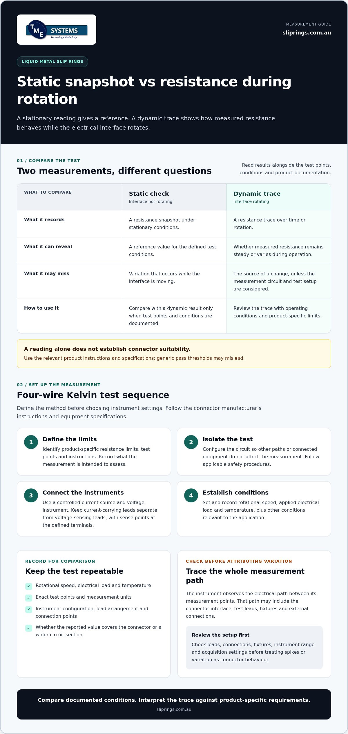
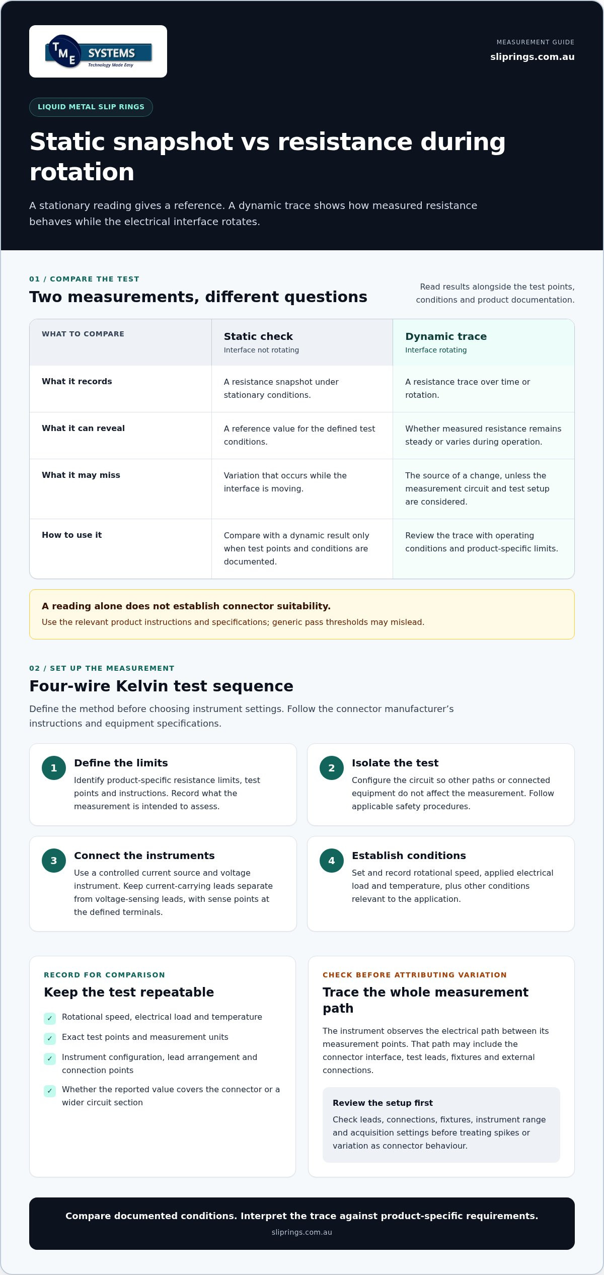
A static check measures resistance while the interface is not rotating. It provides a snapshot under those conditions. A dynamic trace shows how the measured resistance behaves across rotation, which can reveal variation that a stationary value cannot capture. Compare both only when their test points and conditions are clearly documented. Neither measurement alone establishes overall connector suitability. The results need to be considered with the intended application and the product’s own specifications.
Which resistance is the test actually measuring?
The instrument observes the complete electrical path between its measurement points. That path can include the connector interface, test leads, fixtures and external connections. Unless these contributions are managed, an apparent change in connector resistance may instead come from a loose connection, moving lead or fixture effect.
Four-terminal sensing helps separate the voltage measurement from the current-carrying leads. In a four-wire test setup, separate sense leads measure voltage across defined points, reducing the influence of lead and connection resistance on a low-resistance reading. It does not remove the need for sound connections or a controlled fixture. Before comparing readings, write down the exact test points, measurement units and whether the reported value covers the connector alone or a wider section of the circuit.
Use the relevant product instructions and product-specific resistance limits to interpret results. Generic pass thresholds can mislead because test methods, measurement points and connector requirements differ. If a trace raises questions, technical application consulting can help relate the recorded conditions to application-specific selection. For a product-family reference, see Prosper Rotation slip rings; evaluate any connector against its own documentation and operating requirements.
Prepare a four-wire test setup for measuring resistance during rotation
A useful rotating resistance test starts with a defined method, not a convenient instrument setting. For liquid metal slip rings Australia-wide, use the connector manufacturer’s test instructions and the equipment specifications to set the current, measurement range and acquisition settings. Don’t assume a generic test current or pass threshold applies.
- Define the limits. Identify the relevant product-specific resistance limits, test points and test instructions. Record what the measurement is intended to assess.
- Isolate the test. Configure the circuit so other paths or connected equipment don’t affect the measurement. Follow applicable safety procedures before making connections.
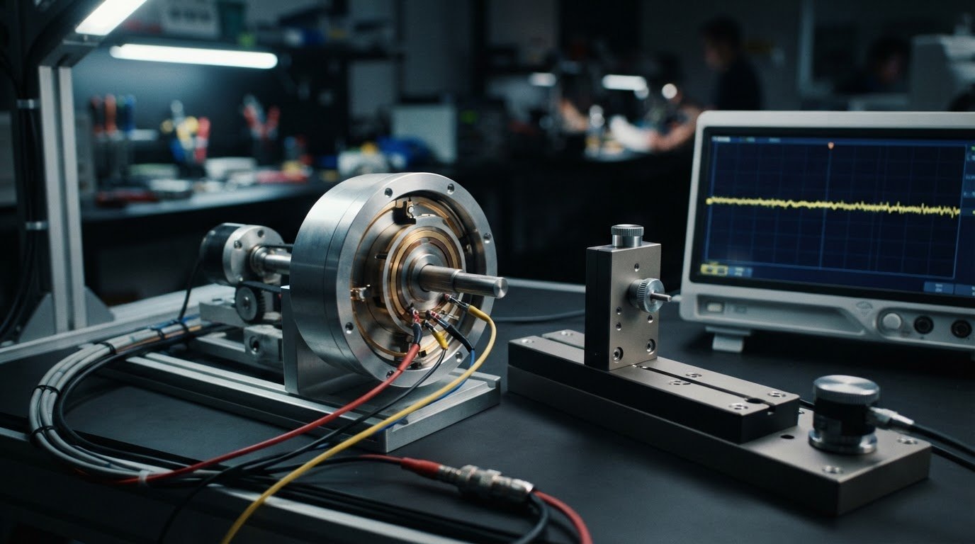
- Connect the instruments. Use a controlled current source and a voltage measurement instrument in a four-wire Kelvin arrangement. Keep current-carrying leads separate from voltage-sensing leads, with the sense points at the defined measurement terminals.
- Establish operating conditions. Set and record rotational speed, applied electrical load and temperature, along with other conditions relevant to the application.
Choose and connect the measurement equipment
The current source applies the specified test current through the connector, while the voltage instrument measures the drop across the chosen test points. In the Kelvin arrangement, separate sense leads measure voltage without carrying the test current, reducing the influence of lead and connection resistance. Select an instrument range and acquisition capability suited to the expected signal, then verify those settings against the equipment specifications.
Control the rotating test conditions
Keep rotational speed consistent across runs intended for comparison. Record temperature, electrical load and any other operating conditions that may affect the trace. Also document instrument configuration, lead arrangement and connection points so another run can reproduce the setup. Follow the connector manufacturer’s instructions and applicable safety procedures throughout the test.
For broader design context, the NASA report on liquid metal slip ring design and testing discusses the development and feasibility of a gallium-based connector. Treat it as engineering background, not a substitute for the specific test instructions and limits that apply to the connector under assessment.
If the setup or results need to be related to an application, technical application consulting for slip ring selection can help frame the engineering review around the recorded conditions and requirements.
Measure and compare resistance traces from liquid metal rotary connectors
Use a consistent sequence so each trace has a clear reference point. A four-wire measurement principle can be applied while a connector rotates if the instrument connections, fixture and acquisition system permit it. Confirm the arrangement is suitable for the connector and test equipment before starting, then keep the measurement points and method consistent across runs.
| Test stage | What to do | What to record |
|---|---|---|
| Stationary baseline | Measure with the connector at rest using the defined test points. | Resistance reading, instrument configuration and connection points. |
| Rotation | Begin rotation and capture resistance against time or rotational position. | Speed, trace data and acquisition settings. |
| Operating condition | Repeat or extend the measurement under the specified electrical load and relevant operating conditions. | Load, temperature and any changes to the test setup. |
| Repeated run | Repeat the sequence under comparable conditions. | Run details and whether the trace pattern is repeatable. |
Capture a trace that can be interpreted
Synchronise resistance readings with time or rotational position so a variation can be related to the connector’s operation. Choose acquisition settings that can capture the changes relevant to the test, and verify the required bandwidth against the instrumentation and measurement objective. Settings that are too slow may smooth or miss brief changes; settings that are poorly matched to the signal can also produce data that is difficult to interpret. Record the chosen settings and repeat the measurement under documented, comparable conditions.
Compare technologies on equivalent terms
Liquid metal rotary connectors use a conductive liquid metal contact path. Other contact methods have different physical interfaces, so don’t assume they will produce the same resistance trace or share the same limits. Compare results only when test current, measurement points, rotational speed, load, temperature and acquisition method are equivalent, and interpret each trace against the applicable product instructions. There is no universal benchmark that can replace product-specific criteria.
NASA’s liquid metal slip ring development report documents design and testing work on a liquid metal slip ring, offering engineering context for evaluating performance under defined conditions. It doesn’t establish acceptance limits for other products. For product context, see the Mercotac slip ring range, while basing measurement conclusions on the specific unit’s documentation and your recorded test data. This disciplined comparison supports informed assessment of liquid metal slip rings Australia applications without treating a product listing as test evidence.
Interpret resistance changes and troubleshoot unreliable readings
A resistance trace needs interpretation before it can support a decision. Look first at its shape and repeatability, not at an assumed pass or fail value. A stable section suggests the reading remained consistent under the recorded conditions. A variation that recurs in matched runs may reflect repeatable behaviour, while an isolated spike could come from the connector, the measurement path or data acquisition. None of these patterns, by itself, proves a fault or confirms suitability.
Check the test system before assigning a change to the rotating interface. Review leads and connections for looseness or movement, check fixture security and probe placement, then confirm the instrument range and acquisition settings. Consider whether a trace feature coincides with a change in speed, load or temperature. If the setup changed between runs, treat the results as different tests rather than direct comparisons.
Separate measurement artefacts from repeatable connector behaviour
Repeat the run under matched conditions and see whether the same pattern returns. Inspect the measurement path for moving leads, inconsistent connections or shifting fixtures. If you alter a connection, instrument setting or mounting arrangement, record the change and establish a new comparison baseline. This helps distinguish a repeatable trace feature from an effect introduced by the test setup.
Report results so another engineer can reproduce the test
Make the record usable by someone who wasn’t present. Include the connector identification, test date, measurement points, instrument configuration, rotational speed, temperature and applied load. Describe trace features in neutral terms, such as a stable section, recurring variation or isolated spike. State the reference limits used and their source, or clearly note that no limits were applied.
- Stable sections: Record the operating conditions and duration represented by the trace segment.
- Repeatable variation: Note where it occurs and whether it aligns with a recorded change in speed, load or temperature.
- Isolated spikes: Check connections, fixtures and acquisition settings before drawing conclusions about the connector.
Escalate unexplained or repeatable deviations by comparing them with the applicable product documentation and engineering requirements. Avoid applying generic acceptance limits: the relevant criteria depend on the connector and test method. For engineers reviewing liquid metal slip rings Australia applications, a clear test record gives technical application consulting a sound basis for interpreting results and identifying what needs further investigation.
Need help relating resistance results to an application? Discuss your slip ring test and selection requirements.
Use measurement results to guide liquid metal slip ring selection and engineering review
A resistance trace is one input to connector selection, not a product ranking. Use repeatable findings to describe electrical behaviour under the conditions tested, then assess them alongside the application’s electrical, mechanical and environmental requirements. A single test result can’t predict service life or establish suitability on its own. If the operating conditions differ from those in the test, review the result in that context rather than assuming it transfers directly.
When resistance data should influence connector selection
Consider whether observed resistance behaviour matters to the application’s operating requirements and measurement objectives. A stable or repeatable trace can support an engineering assessment, but it doesn’t replace checks against product documentation. Reassess suitability if the intended speed, load, temperature or other operating conditions differ from the documented test. This keeps selection decisions tied to evidence without turning one measurement into a general performance claim.
What to include in a final engineering review
Bring the test record together with the application details. This allows technical review to consider the connector’s measured behaviour and the requirements it must meet.
- Electrical: circuit count, current and voltage.
- Mechanical: rotational speed rating and mounting style.
- Environment: relevant operating conditions, including temperature and exposure factors.
- Measurement evidence: test method, resistance trace, measurement points, instrument configuration and recorded conditions.
State which product limits or engineering requirements were used to assess the result, and identify their source. If AS/NZS 5368:2025 is being considered, first establish that its scope, electrical equipment in mines and quarries, applies to the application. Don’t cite it as a general requirement for a resistance test without that link.
For broader context on the technical review process, read the slip ring application engineering guidance. It can help frame the application information required alongside test findings. For liquid metal slip rings Australia-wide, this evidence-led approach supports a more relevant engineering discussion than choosing on a resistance value alone.
If you’re reviewing measured results against a rotary connector application, discuss your rotary connector application with TME Systems’ technical team.
Turn resistance measurements into a confident engineering decision
Meaningful dynamic resistance data depends on a controlled test. A four-wire setup can reduce the influence of lead resistance, while recording speed, load, temperature and instrument settings gives each trace the context needed for comparison.
Repeatable changes deserve attention, but check the measurement path and test conditions before attributing them to the connector. Interpret findings against product-specific instructions and limits, then consider them alongside circuit count, electrical requirements, mounting and environment. A resistance reading is useful evidence, not a complete measure of service life or application suitability.
For engineers assessing liquid metal slip rings Australia-wide, TME Systems provides technical assistance with slip ring selection and application requirements. Discuss your test findings and operating needs with the technical team to support your next engineering decision. Discuss your rotary connector application, and move forward with a clearer basis for selection.
Frequently Asked Questions
How do you measure dynamic contact resistance?
Apply the test current specified for the connector and monitor the voltage across defined measurement points while the interface rotates. With a suitable four-wire setup, calculate resistance from the measured voltage and current, then record the trace against time or rotational position. Document speed, load, temperature and instrument settings as well. Interpret the data using the connector’s test instructions and product-specific limits, rather than a generic threshold.
Can a multimeter measure contact resistance while a slip ring is rotating?
A standard multimeter may display readings during rotation, but that doesn’t mean it can capture a useful dynamic trace. Its measurement rate or display may average over fluctuations or miss brief changes. Check the instrument’s sampling and logging capability against the variation you need to observe. For interpretable results, use an appropriate measurement setup that can record resistance alongside time or rotational position under controlled conditions.
Why use the four-wire Kelvin method for contact resistance?
The four-wire Kelvin method separates the current-carrying leads from the voltage-sensing leads. This reduces the influence of lead and connection resistance on the measured voltage, which matters when assessing low resistance. Place the sense connections at clearly defined test points and keep them secure during rotation. The method doesn’t correct every setup error, so fixtures, connections and instrument settings still need to be controlled and recorded.
What causes dynamic contact resistance to fluctuate?
Fluctuation may reflect changes at the rotating electrical interface, but it can also come from the test setup. Check for moving leads, loose connections, unstable fixtures, inconsistent probe placement or unsuitable instrument range and acquisition settings. Compare the trace with recorded speed, load and temperature to see whether changes coincide. Repeat the measurement under matched conditions before deciding whether a pattern is consistent or an isolated reading.
Can liquid metal rotary connectors be tested using the same method as brush slip rings?
The four-wire measurement principle can be used for different connector types if the rotating setup permits it. However, liquid metal rotary connectors use a conductive liquid metal contact path, while brush slip rings use a different contact arrangement. Don’t assume their trace patterns, test instructions or resistance limits are interchangeable. For engineers assessing liquid metal slip rings Australia-wide, interpret each result against the relevant connector documentation and comparable test conditions.
What does a high dynamic contact resistance reading mean?
A high reading signals a result to investigate, not an automatic diagnosis of connector failure. First check the defined measurement points, test current, connections, leads, fixture, instrument range and acquisition settings. Review whether speed, load or temperature differed from the intended conditions, then repeat the test consistently. Compare the verified result with the applicable product-specific limits and engineering requirements before deciding whether further technical review is needed.
How should dynamic contact resistance results be reported?
Include the connector identification and test date, measurement points, test method, instrument configuration and settings. Attach the resistance trace and state whether it is recorded against time or rotational position. Record rotational speed, temperature, electrical load and any setup changes, then note whether repeated runs showed similar behaviour. Identify the reference limits used and their source, or state clearly that no limits were applied. This gives another engineer a basis for reviewing or reproducing the test.