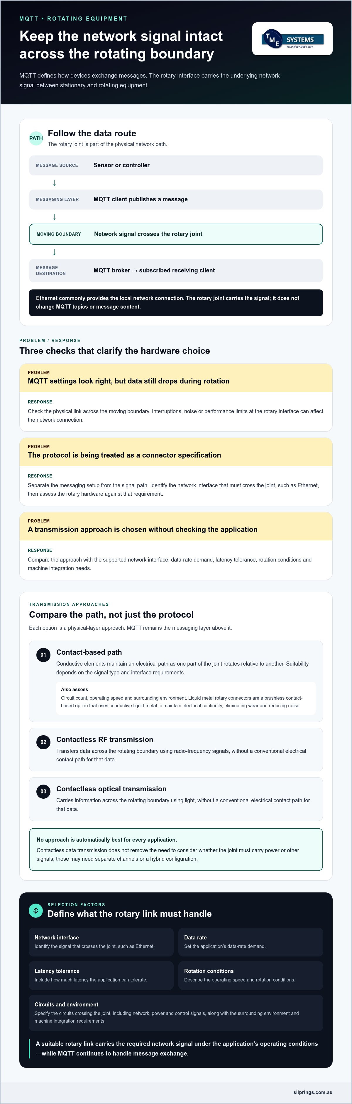
What if an MQTT link is configured correctly, but data still drops as equipment rotates? MQTT data transmission through a rotating joint depends not on a special MQTT interface, but on maintaining the underlying network connection across the moving boundary. MQTT is the messaging layer. The rotary electrical joint must carry a suitable signal path, often Ethernet, between stationary and rotating equipment.
It’s reasonable to focus on protocol settings, broker reliability and device compatibility. But those cannot compensate for a rotating interface that interrupts the connection or introduces noise or performance limits. The joint’s electrical characteristics, operating speed and environment all affect whether the network link meets the application’s requirements.
This article explains how MQTT relates to Ethernet and the rotary interface, then compares contact-based and contactless transmission approaches. You’ll learn what to define, including data rate, circuit count, rotational speed, mounting style and environmental conditions, to prepare a practical specification for application engineering and hardware selection.
Key Takeaways
- MQTT data transmission through a rotating joint relies on the rotary interface carrying the network signal, not on a special MQTT connection.
- Trace the complete data path from sensor or controller through the MQTT client and broker to the receiving client to identify where the rotating link fits.
- Compare contact-based, RF and optical approaches against interface compatibility, data-rate needs, latency tolerance and operating conditions.
- Build a specification that separates electrical, mechanical, network and environmental requirements, then validate it through bench and system-level testing.
- Application engineering can translate circuit count, current, voltage, speed, mounting style and environment into a rotary-joint selection discussion.
What MQTT Does in Data Transmission Through a Rotating Joint
MQTT defines how connected devices publish and receive messages. It does not define the electrical connector or rotary hardware that carries those messages. In a common industrial arrangement, MQTT traffic travels over a network stack such as TCP/IP, with Ethernet providing the local network connection. Other network interfaces may be used, depending on the system.
MQTT is a lightweight, publish-subscribe machine-to-machine messaging protocol. A publisher sends a message under a topic, and a broker routes it to clients subscribed to that topic. The message might report a motor’s temperature or indicate a change in machine state. MQTT describes the message exchange; the network beneath it moves data between devices.
Where MQTT sits in an industrial data path
Consider a sensor on a rotating platform that reports vibration readings. The sensor, or a connected controller, acts as an MQTT client and publishes readings to a topic such as platform/vibration. The message travels over the network to an MQTT broker. A monitoring application subscribed to that topic receives the update through its own MQTT client.
Trace the route from sensor or controller, through the MQTT client and network link, to the broker and receiving client. MQTT topics organise messages, while Ethernet framing carries network packets across an Ethernet segment. The physical connection carries the electrical or optical signal. These layers work together, but they are not interchangeable: changing the rotary hardware does not change the MQTT topic or message format.
What changes when the connection rotates
If the publisher is mounted on a rotating assembly and the broker or receiving equipment is stationary, the network signal must cross the moving boundary. A rotary electrical joint forms part of that physical route. Its job is to maintain a suitable connection as the equipment turns, while devices continue exchanging MQTT traffic in the same way.
The protocol defines how devices exchange messages; the physical link determines how those messages travel between stationary and rotating equipment. That distinction matters when specifying MQTT data transmission through a rotating joint. MQTT does not dictate a particular slip-ring design. Hardware selection depends on the required network interface and application conditions, including rotation, electrical continuity and signal integrity.
For example, identify whether the rotating side uses Ethernet, how the network is routed across the joint, and what conditions apply during rotation. These details establish the signal-path requirements. The same MQTT configuration may work with different physical transmission approaches, but each approach must suit the network interface and the machine’s operating demands.
Keep protocol and hardware questions separate during early design. Define how devices publish, subscribe and connect to the broker, then specify the network signal that must cross the rotary joint. This gives application engineering a clear basis for assessing electrical and mechanical requirements without treating MQTT as a special connector format.
How MQTT Data Crosses a Rotary Electrical Joint
Once the network signal reaches the rotating boundary, the joint must provide a physical path between the stationary and rotating sides. The right approach depends on the interface being carried and the machine’s operating conditions. MQTT remains above this layer: the rotary connection carries network traffic rather than interpreting MQTT topics or changing message content.
Contact-based paths and liquid metal rotary connectors
In a contact-based arrangement, conductive elements maintain an electrical path as one part of the joint rotates relative to another. This can provide a route for network signals, but suitability depends on the signal type and interface requirements, not simply on whether the connector has enough electrical paths. Circuit count, operating speed and the surrounding environment also inform selection.
liquid metal rotary connectors are brushless rotary connectors that use a pool of conductive liquid metal to maintain electrical continuity, eliminating wear and reducing noise. They are one contact-based option, not a blanket solution for every network. Assess the required signal path and operating conditions before selecting a configuration.
For example, a machine may need separate paths for network data, power and control signals. Specify which circuits cross the joint and how the network interface is arranged. A rotary assembly may combine functions, but define the required channels and their electrical characteristics before assessing suitability for MQTT traffic.
Contactless RF and optical transmission
Contactless methods transfer data across the rotating boundary without a conventional electrical contact path for that data. RF transmission uses radio-frequency signals; optical transmission carries information using light. Both are physical-layer approaches. Neither changes MQTT itself, and neither is automatically the better choice for every rotating application.
Compare the approaches against the actual requirements: supported network interface, data-rate demand, tolerance for latency, rotation conditions and integration with the machine. Also consider whether the joint must carry power or other signals, which may require separate channels or a hybrid configuration combining transmission methods. Assess the complete signal path, not just the data crossing the rotary interface.
Free-space optical transmission is one example of an optical approach to data transfer through a rotary joint. Its relevance to a particular system depends on how the optical link integrates with the required network interface and equipment.
For MQTT data transmission through a rotating joint, define the network interface first, then compare contact-based, RF and optical paths against the application’s electrical and mechanical requirements. TME Systems provides technical application consulting to help translate those requirements into a rotary-connector selection discussion. This can include consideration of Prosper Rotation slip rings as part of the available product range.
Compare MQTT Rotary-Joint Options Against the Application
Compare transmission approaches against the full application, rather than choosing by technology label alone. A contact-based, RF or optical path may be suitable if it supports the required network interface and operating conditions. Capture what the system needs and what must be validated, without assuming one approach is always faster or more reliable.
Which technical criteria should the comparison include?
Start with the communications requirement: record the network interface, required throughput, message frequency and acceptable delay. A system sending occasional status updates has a different traffic profile from one transmitting frequent measurements. Define the expected traffic rather than relying on a general description such as “MQTT data”.
Then add mechanical and electrical details. Record the rotational speed rating, operating cycle, mounting style, available space, circuit count, voltage and current. Include environmental conditions relevant to the installation. These inputs let application engineering assess the rotary connector as part of the system, rather than as an isolated data component.
How to interpret reliability and MQTT Quality of Service
MQTT Quality of Service (QoS) describes message-delivery behaviour between MQTT clients and the broker. QoS 0 sends a message without a delivery acknowledgement, QoS 1 confirms delivery but can result in duplicates, and QoS 2 uses a more involved exchange to provide exactly-once delivery at the MQTT level. The suitable level depends on the system architecture and the consequences of missed or repeated messages.
MQTT settings cannot substitute for a suitable physical link. QoS does not establish electrical continuity across a rotary joint, remove signal errors or keep a network link available. Network reconnection and application recovery address what devices do after an interruption; they are distinct from the hardware’s ability to carry the signal during rotation. Testing should examine both message behaviour and physical-link performance under representative operating conditions.
For MQTT data transmission through a rotating joint, document the interface, traffic profile and mechanical constraints before comparing options. TME Systems’ technical application consulting can help relate these requirements to circuit count, current, voltage, speed, mounting and environment. Discuss your rotary-connector application as part of that specification process.
Specify and Validate MQTT Data Transmission Through a Rotating Joint
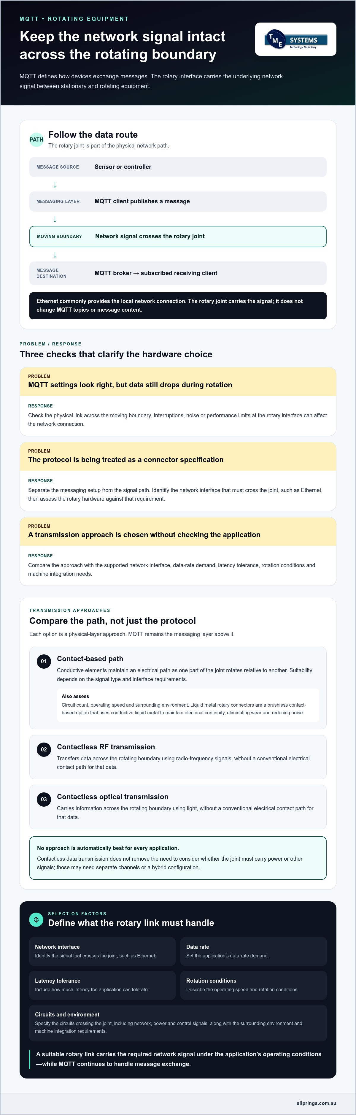
A useful engineering brief separates network requirements from the electrical, mechanical and environmental demands on the rotary hardware. This makes it easier to assess the complete signal path, then validate it under conditions that reflect how the equipment will operate.
What to include in the engineering brief
Describe the communications path first: network interface, required data rate, message pattern, acceptable latency and system topology. Note where the MQTT clients and broker sit, and what the system must do if communication is interrupted. These details define the network behaviour that testing needs to verify.
Record the hardware requirements separately. Include rotational speed rating, operating cycle, mounting constraints, available space, circuit count, current and voltage. Describe the ambient conditions and any relevant IP rating, a standard that defines the level of protection against dust and water ingress for electrical equipment. This gives application engineering a clear basis for assessing hardware options against the installation.
How to validate the assembled data path
Agree acceptance criteria before testing. They should reflect the project’s required message delivery, response time and recovery behaviour, rather than assumed performance. Keep test observations distinct from manufacturer specifications and third-party product claims, as each describes different evidence.
- Define the interface and topology. Document the network connection, MQTT client and broker arrangement, message pattern and expected traffic.
- Separate requirement groups. List electrical, mechanical, network and environmental needs so an unmet requirement is visible and traceable.
- Assess the rotary hardware. Compare candidate configurations against the defined interface, circuit count, current, voltage, speed, mounting and environment.
- Bench-test the signal path. Run representative MQTT traffic while the joint rotates and the system operates under relevant load and application conditions.
- Validate the complete system. Check packet delivery, interruptions, reconnection and application response against the agreed criteria, including recovery after a link interruption.
Testing should reflect the expected message frequency and traffic pattern, not just a brief connection check. Observe whether the application receives and handles data as intended throughout rotation. If a disruption occurs, record both the physical-link behaviour and the network or application response. This helps distinguish a signal-path issue from reconnection logic or message-handling behaviour.
Include security in the network and device design. Define authentication, access controls and any encryption requirements for the connections between clients and broker. A rotary joint carries the physical signal; it does not itself provide MQTT security or encryption. Document security controls and test results alongside the interface and operating requirements.
For MQTT data transmission through a rotating joint, application engineering can turn these requirements into a rotary-connector specification and hardware selection discussion. Discuss your rotary-joint application with TME Systems’ technical application consulting team.
Turn the MQTT Requirement into a Rotary-Joint Specification with TME Systems
An MQTT requirement becomes useful for hardware selection when it is described as a complete application, not simply as a request for an “MQTT-ready” slip ring. TME Systems’ technical application consulting helps translate network and mechanical needs into a rotary-connector specification. The discussion centres on the interface, required circuits, electrical loads, rotation, mounting and operating environment.
How application engineering narrows the hardware options
Start with the signal path that must cross the rotating boundary. Identify its network interface and how it fits alongside power, control or other signals. Then consider circuit count, current, voltage and operating speed together. A rotary joint is part of a wider machine assembly, so assess electrical requirements alongside mounting style, available space and operating conditions.
This process helps distinguish essential requirements from preferences. For instance, a compact mounting envelope may shape the available configurations, while the operating environment may affect the hardware assessment. A selection should follow from the documented application requirements, rather than assume one product category suits every MQTT installation. Broader procurement considerations can inform the process, but should remain separate from technical compatibility.
Prosper Rotation slip rings are one product category to consider as part of the hardware discussion. Their suitability for a particular network path depends on the application requirements and engineering assessment, not on the MQTT protocol alone. TME Systems also supplies industrial slip rings from Mercotac, Meridian Laboratory and BGB Innovation, alongside Prosper Rotation products.
What to provide for a useful technical review
Give the application engineer a concise description of what the machine does and which parts rotate. Identify the equipment on the stationary and rotating sides, then map the data path between them. Include where the MQTT clients and broker sit in the system, along with the network interface that needs to cross the joint.
Useful details include:
- The network interface, expected traffic pattern, data-rate demand and acceptable delay.
- The required circuit count, current and voltage, including other signals or power that must pass through the assembly.
- The rotational speed rating, duty cycle, mounting style, available space and mechanical constraints.
- The operating environment and relevant ingress-protection requirements.
- Known interruptions or recovery expectations that should shape later validation.
Clear inputs support a focused discussion of suitable hardware and any testing needed to assess the assembled data path. They also keep network requirements distinct from the rotary connector’s electrical and mechanical demands. Assess the interface and application before treating any connector as suitable for MQTT traffic.
For MQTT data transmission through a rotating joint, share your machine function, data path and installation constraints with TME Systems. The technical application consulting team can use those details to guide a hardware selection discussion grounded in your requirements.
Make the Signal Path a Defined Design Requirement
Carry the rotary network requirement into the project’s design and commissioning documents. A clear specification gives engineering, procurement and commissioning teams a shared basis for assessing the hardware and checking the assembled system. It also keeps MQTT configuration, physical transmission and recovery expectations distinct as the design develops.
For MQTT data transmission through a rotating joint, connect the machine’s operating needs with a practical rotary-connector selection. TME Systems’ technical application consulting supports this process, using application details to guide a hardware discussion. The aim is a specification grounded in the installation, not an assumption that a particular connector suits every network.
Bring your project requirements into the discussion and identify questions to resolve before selection or validation. Discuss your rotary-joint application with TME Systems and take the next step towards a signal path designed around your equipment.
Frequently Asked Questions
Can MQTT messages be buffered if the rotating data link is interrupted?
Yes, buffering may be configured in an MQTT client, broker or application, depending on the system design. A stored message is not automatically guaranteed to be delivered after a physical-link failure. Specify how long an interruption may last, where queued data resides, how much storage is available and whether old readings should be discarded or sent after reconnection. Test the configured behaviour in the assembled system.
Does a rotating joint change MQTT topic names or message payloads?
Normally, topic names and payloads are set by the publishing application, and the receiving application interprets them. A gateway or controller between endpoints can, however, map topics, reformat data or filter messages. For instance, a gateway might convert a sensor’s data structure before forwarding it. Document which device creates each message, any intermediate processing, and which client consumes the final data so changes are traceable.
Can one rotary joint carry MQTT data and electrical power at the same time?
A joint may be configured for both functions, but the arrangement depends on its design and the application’s electrical requirements. Provide the power load and data interface as distinct inputs, including their ratings and operating conditions. The engineering review can then consider how they fit within the assembly and whether the proposed configuration meets each requirement. Don’t infer combined capability from a connector’s general description alone.
Does MQTT over TLS require a different rotary-joint design?
Not necessarily. TLS may affect endpoint configuration and connection behaviour, including certificate management, session establishment and the resources required by the client. Those details belong in the system design alongside the network interface. Confirm that the devices and broker use compatible security settings, and include the secured configuration in commissioning checks. This helps identify issues in the wider communication setup rather than attributing every connection problem to rotary hardware.
What should be logged during MQTT rotary-link testing?
Use synchronised timestamps and a message identifier or sequence value where the application supports it. Record the test setup, client and broker configuration, rotation state, message topic and relevant QoS setting. Correlating these details can help trace a missing, delayed or duplicated reading to a particular point in the test. Keep raw logs with a brief record of configuration changes so results remain interpretable later.
Is MQTT suitable for time-critical control through a rotating joint?
It depends on the control function. Distinguish supervisory data, such as monitoring or set-point reporting, from a closed-loop function that depends on predictable timing. For the latter, consider timing variation as well as average response, and define what the machine should do if an update arrives late or is unavailable. Assess MQTT as one part of the control architecture, not as evidence by itself that the function meets its timing needs.