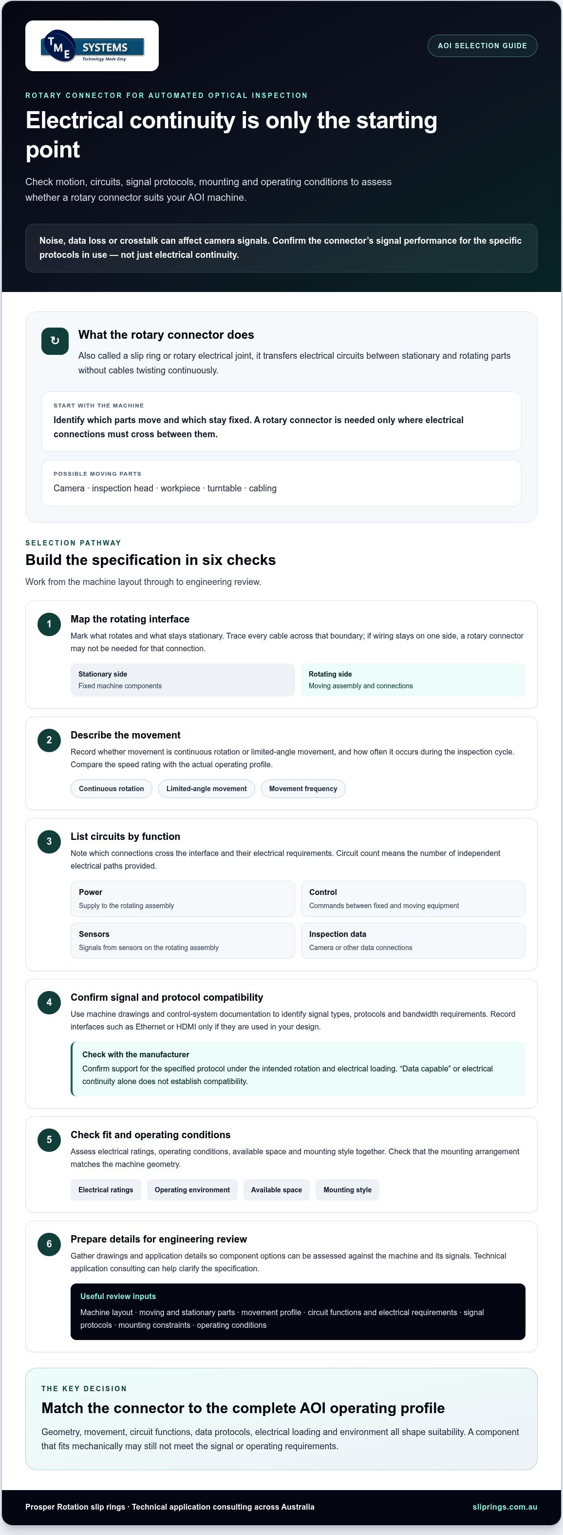
A rotary connector can maintain electrical continuity and still compromise an AOI inspection if noise, data loss or crosstalk affects camera signals. Choosing a rotary connector for automated optical inspection (AOI) therefore involves more than counting circuits. The rotating assembly’s geometry, movement and inspection duty all matter.
To determine whether a connector will suit the machine and its signals, assess operating speed and rotation, power and signal requirements, mounting constraints and environmental conditions. This guide explains what to check, including compatibility with the specific data protocols in use. Electrical continuity alone does not establish that a connector can handle an AOI system’s signals.
TME Systems supplies Prosper Rotation slip rings and provides technical application consulting to help customers across Australia select components. Use the steps below to build a clear specification and prepare the details needed for an engineering review, so you can assess options against your application.
Key Takeaways
- Identify which AOI assembly rotates and which components stay stationary. This defines the rotary interface to assess.
- Specify movement, circuit count, electrical ratings and operating conditions before comparing connector options.
- For a rotary connector for automated optical inspection (AOI), confirm support for the required data protocols and signals, not just electrical continuity.
- Check mounting style against the machine geometry and compare the speed rating with the actual operating profile.
- Prepare drawings and application details for review so TME Systems can provide technical application consulting on suitable component options.
What does a rotary connector do in an AOI system?
A rotary connector transfers electrical circuits between stationary and rotating parts of a machine. Also called a slip ring or rotary electrical joint, it allows selected connections to cross a rotating interface without cables twisting continuously. For a foundational explanation of this electromechanical device, see Wikipedia.
Definition: A rotary connector for automated optical inspection (AOI) carries specified electrical paths across the rotating part of an inspection machine. Its suitability depends on the machine’s movement, circuit functions and operating requirements. It is not automatically compatible with every AOI system or signal type.
Start with the machine layout, not a connector catalogue. AOI designs vary: a camera or inspection head may move, a workpiece may rotate on a turntable, or the entire assembly may turn. Identify stationary components too. A rotary connector is needed only where electrical connections must cross between moving and fixed sections.
Which parts of an AOI machine may rotate?
Map the camera, inspection head, workpiece, turntable and cabling. Mark which parts move and which remain fixed, then trace every cable across that boundary. If wiring can stay on one side, a rotary connector may not be needed for that connection.
Record whether movement is continuous rotation or limited-angle movement, and how often it occurs during the inspection cycle. The duty cycle helps define what the connector must accommodate over time. A cable flexing through a limited range presents a different arrangement from a connection that passes through repeated or continuous rotation. Confirm the movement profile before comparing options.
What information should cross the rotating interface?
List each connection by function rather than treating all circuits as interchangeable. Depending on the machine design, these may include:
- Power: circuits supplying the rotating assembly or components on it.
- Control: connections carrying commands between stationary controls and moving equipment.
- Sensor: paths for signals from sensors fitted to the rotating assembly.
- Inspection data: camera or other data connections that must cross the interface.
The circuit count is the number of independent electrical paths a slip ring provides. Identify which functions need separate paths and document their electrical requirements. For high-speed data, note the protocol and required bandwidth, then confirm with the manufacturer that the specific connector design supports them. Continuity alone does not establish signal compatibility. These details give you a clearer basis for comparing designs.
How AOI motion, signals and operating conditions shape connector selection
Once you have mapped the rotating interface, turn the machine’s operating profile into a connector specification. Assess movement, circuit function, electrical ratings, environment and available space together. A connector that fits mechanically may still be unsuitable if its signal performance, electrical capacity or operating limits do not match the application.
Connector suitability depends on the complete operating specification, because motion, electrical loading, signal requirements and environment interact at the rotating interface. This also applies as AOI systems incorporate new inspection approaches. The IPC discusses advancements in technology such as artificial intelligence in AOI, but connector suitability still needs to be checked against the specific machine and signals.
How do signal and data requirements affect an AOI connector?
Use machine drawings and control-system documentation to identify every signal type and protocol that must cross the rotating interface. Record bandwidth and transmission requirements for Ethernet, HDMI or another interface only if it is used in your design. Do not assume a connector supports a protocol simply because it passes electrical continuity.
Ask the supplier to confirm signal performance for the specified protocol under the intended rotation and electrical loading. This assesses the connection as part of the complete system, rather than relying on a general description such as “data capable”. For a rotary connector for automated optical inspection (AOI), protocol-specific confirmation is essential wherever inspection data crosses the rotating joint. Check high-speed data requirements against the specific protocol and bandwidth in use.
Which operating and environmental details belong in the specification?
Record the expected movement pattern, duty cycle and operating conditions, then check the connector’s rotational speed rating against the actual profile. A maximum rating alone may not describe the machine’s pattern of starts, stops or speed changes. Confirm how the proposed design is rated for the way your equipment will operate.
Include voltage, current and circuit count from verified machine requirements. Document available space and relevant environmental exposure too. An IP rating defines the level of protection against dust and water ingress for electrical equipment. Specify the protection your installation requires, then confirm the proposed connector’s rating and suitability with its manufacturer.
- Movement: operating speed, direction, pattern and duty cycle.
- Electrical: voltage, current, circuit count and circuit function.
- Signals: protocols, bandwidth and transmission requirements.
- Installation: available space and environmental conditions, including required IP rating.
With these requirements documented, ask a supplier to review relevant options, including Prosper Rotation slip rings, against your application rather than selecting by category alone.
Which rotary connector technology and mounting style fits your AOI design?
Compare connector options with your documented requirements, not just product labels such as “high speed” or “compact”. Mounting geometry determines how the connector fits the rotating assembly. Contact technology and circuit design must also be assessed against the required electrical paths, signals and operating conditions. A rotary connector for automated optical inspection (AOI) is suitable only when its application-specific performance is confirmed.
| Option or criterion | Mounting and circuit needs | Signals and operating conditions to confirm |
|---|---|---|
| Through-bore slip ring | Hollow centre can fit over a rotating shaft or accommodate auxiliary components. Check bore and surrounding installation space. | Confirm required circuit count, signal compatibility and performance for the specified movement and operating conditions. |
| Capsule design | Compact solid form for end-of-shaft mounting. Check whether the shaft end and available space suit the installation. | Confirm circuit needs, protocols and performance against the same application requirements. |
| Liquid metal rotary connectors | A distinct contact method. Assess circuit provision alongside the machine’s mounting constraints. | Confirm signal or data protocol compatibility and suitability for the intended rotation and operating conditions with the manufacturer. |
When should you compare through-bore and capsule designs?
Use the machine layout to determine which geometry can be installed. A through-bore slip ring has a hollow centre for fitting over a shaft or accommodating auxiliary components. A capsule design is a compact solid unit intended for end-of-shaft mounting. Neither form is universally better. Compare mounting position, shaft arrangement, available clearance and cable access, then confirm the selected design’s specific ratings.
When should you assess liquid metal rotary connectors?
Consider liquid metal rotary connectors when comparing contact methods, but do not infer signal quality or data capability from the contact method alone. Ask the manufacturer to confirm each required circuit and protocol under the intended operating conditions. For relevant product information, see Mercotac slip rings. Verify the particular model’s construction and suitability against the application.
Use the table as a comparison framework, not a product recommendation. Check each candidate against the documented mounting, circuit and operating requirements, and confirm signal performance for the specific product before selection. Resolve unclear specifications before treating a connector as compatible.
How to prepare an AOI rotary connector specification for engineering review
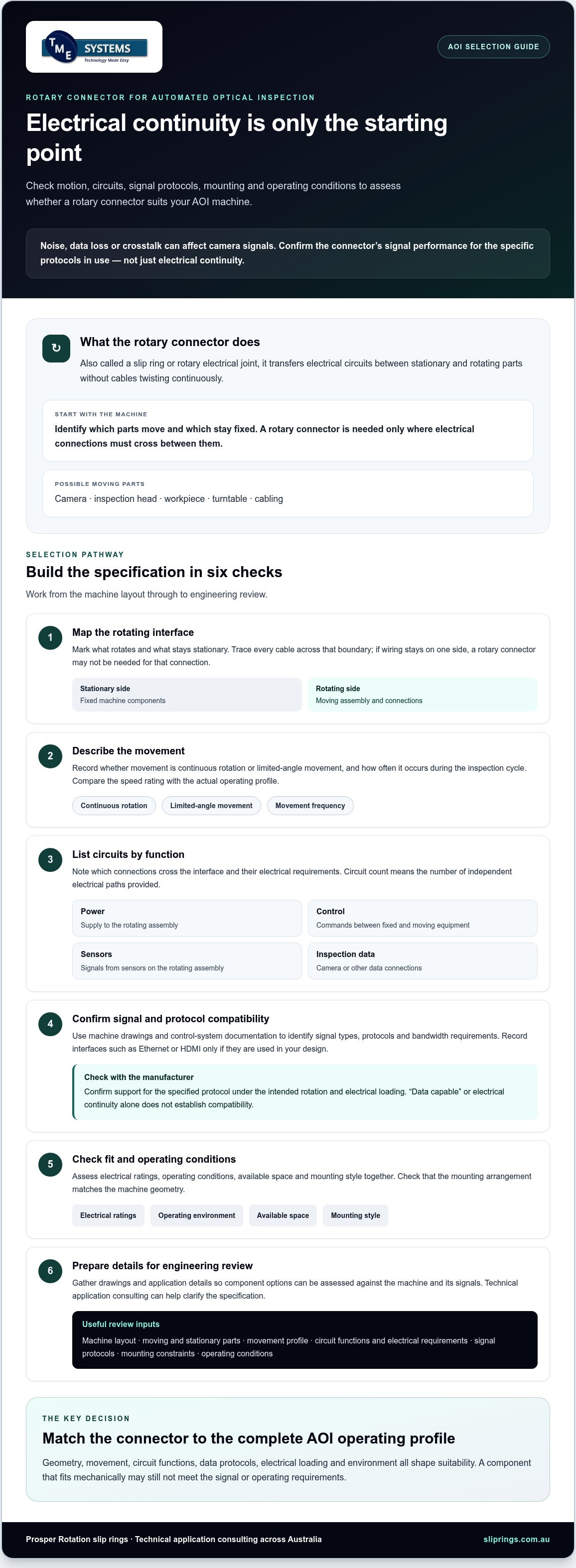
A useful engineering review starts with the machine layout, not a guessed connector rating. Gather drawings and operating information that show what rotates, what stays stationary and which electrical connections cross the interface. Mark unknowns clearly so they can be confirmed instead of filled with assumed defaults.
What should you include in the technical enquiry?
Use this checklist to prepare a reviewable specification for a rotary connector for automated optical inspection (AOI):
- Drawings and rotating assembly: Provide machine layout drawings and identify the rotating assembly, stationary components and rotary interface location.
- Interface and cables: Include interface diagrams and relevant manufacturer documentation. Show shaft arrangement, installation envelope, mounting constraints and cable routing.
- Circuit requirements: State the circuit count and identify the function of each path, such as power, control, sensor or inspection data.
- Electrical ratings: Provide verified voltage and current requirements for each circuit, including relevant loading information from the machine documentation.
- Signals and protocols: Name the signal types and data protocols in use, with bandwidth or transmission requirements where specified by system documentation.
- Operating profile: Describe movement, operating speed, direction, duty cycle and any changes in motion that affect the rotating connection.
- Environment and standards: Record known ambient conditions and exposure, including any required IP rating. List applicable project standards for review, but check their scope rather than assuming they apply.
If a value is unavailable, label it “to be confirmed” and note who can verify it. This makes gaps visible and prevents an unverified estimate from becoming a design requirement.
How should the supplier assess a proposed connector?
Ask the supplier to compare the proposed design against the information supplied in four areas: mechanical fit, electrical requirements, signal performance and operating environment. Request confirmation of any unverified mounting or operating ratings, plus protocol-specific performance under the intended conditions. If the design changes, for example, through a different rotating assembly or data interface, update the specification before approval.
TME Systems provides technical application consulting to help assess component options against supplied requirements. Share drawings, the operating profile and electrical and signal details, including open questions, to support a focused review. Discuss your AOI connector requirements with TME Systems.
Choose an AOI rotary connector with application-specific technical support
Selecting a rotary connector for automated optical inspection (AOI) involves a sequence of checks: define the rotating interface, document its requirements, compare suitable designs and confirm the fit. A connector’s category or form factor can help narrow options, but does not confirm compatibility with a particular AOI machine.
Before settling on a design, check that its mounting arrangement fits the machine geometry and its electrical ratings match the documented loads. Confirm support for required signals and protocols, and review operating and environmental conditions with the manufacturer. If project standards apply, check their relevance against project documentation and seek qualified advice as needed. AS/NZS 5368:2025 should not be assumed to apply to an AOI installation unless its scope has been verified for that application.
How can TME Systems support the selection process?
TME Systems supplies industrial slip rings and rotary electrical connectors to customers across Australia, and provides technical application consulting for component selection. The aim is to assess potential options against the requirements you supply, not to assume a connector is suitable based on its name or a general description.
For a relevant product category reference, see Meridian Laboratory slip rings. Confirm specific mounting, speed, electrical or signal capabilities with the relevant manufacturer before treating a product as a match for your AOI application.
To make the discussion useful, prepare machine drawings and details of the rotating assembly. Include movement and duty cycle, mounting constraints, circuit count, voltage and current requirements, signal protocols and known operating conditions. Flag anything not yet confirmed so it can be addressed rather than replaced with an assumption.
Discuss your AOI connector requirements with TME Systems’ technical team. Share the available interface details so component options can be considered against your application.
Make your AOI connector choice with confidence
A sound selection starts by defining the rotating interface and documenting what must pass through it. Record the machine’s movement, mounting constraints, circuit requirements, electrical ratings, signal protocols and operating conditions. Compare connector designs with those details, then confirm product-specific performance with the manufacturer before approval.
This process helps you assess a rotary connector for automated optical inspection (AOI) on application fit rather than assumptions about a connector category or form. Flag unknown requirements for review instead of filling gaps with estimates.
TME Systems supplies industrial slip rings and rotary electrical connectors to Australian customers, with technical application consulting to help assess component options against supplied requirements. Share your drawings and operating, electrical, signal and mounting details for a focused technical discussion.
Discuss your AOI connector requirements with TME Systems. A clear specification and confirmed requirements give you a practical basis for choosing a connector.
Frequently Asked Questions
What does a rotary connector do in an AOI machine?
A rotary connector transfers electrical circuits between stationary and rotating parts of an AOI machine. It can carry power, control, sensor or inspection-data circuits where connections cross the rotating interface. First identify which assembly moves and which components stay fixed. If a cable can remain entirely on one side of the interface, a rotary connector may not be needed for that connection.
How do I choose a rotary connector for automated optical inspection?
Choose a rotary connector for automated optical inspection (AOI) by matching its confirmed capabilities to the machine’s requirements. Document the rotating assembly, mounting geometry, movement profile, circuit count, voltage, current, signal protocols and environmental conditions. Compare designs against these details, then ask the manufacturer to confirm mechanical fit, electrical ratings and protocol-specific performance under the intended operating conditions. A product category alone does not guarantee compatibility.
Can a slip ring transmit Ethernet or other high-speed data in an AOI system?
A slip ring may be suitable for Ethernet or other high-speed data transmission, but compatibility must be confirmed for the specific design and protocol. Check the required data rate and interface against machine or control-system documentation. Ask the manufacturer to verify signal performance under the intended rotation and electrical loading. Electrical continuity alone does not confirm that data will pass without unacceptable distortion, noise or loss.
What information should I provide when requesting an AOI rotary connector recommendation?
Provide machine layout drawings, interface diagrams and details of the rotating assembly. Include mounting and shaft arrangements, available space, cable routing, movement pattern, duty cycle and operating conditions. List each circuit’s function, circuit count, verified voltage and current, plus signal types, protocols and bandwidth requirements. Note known environmental exposure and relevant project standards. Mark missing values clearly so they can be confirmed rather than replaced with assumptions.
Is a through-bore slip ring suitable for an AOI system?
A through-bore slip ring may suit an AOI system if its hollow centre fits the machine’s shaft or accommodates required auxiliary components. Check installation geometry, available clearance, mounting arrangement and cable routing against the drawings. Suitability also depends on the required circuits, signals and operating conditions. Confirm the proposed model’s specific ratings with its manufacturer rather than choosing by form factor alone.
When should I consider liquid metal rotary connectors for AOI?
Consider liquid metal rotary connectors as one possible contact technology when comparing options for the documented application. The contact method alone does not establish suitability for AOI signals or data. Confirm required circuit functions, protocols, mounting arrangement and operating conditions with the manufacturer. Request protocol-specific confirmation if inspection data must cross the rotating interface.
Does an AOI rotary connector need a particular IP rating?
Not necessarily. The required IP rating depends on the installation’s exposure to dust or water and any applicable project requirements. Identify those conditions from the machine environment and project documentation, then confirm the protection level needed with the responsible engineering team. Ask the connector manufacturer to verify the proposed model’s IP rating and suitability for the application. Do not select a rating based on assumptions about AOI machines generally.