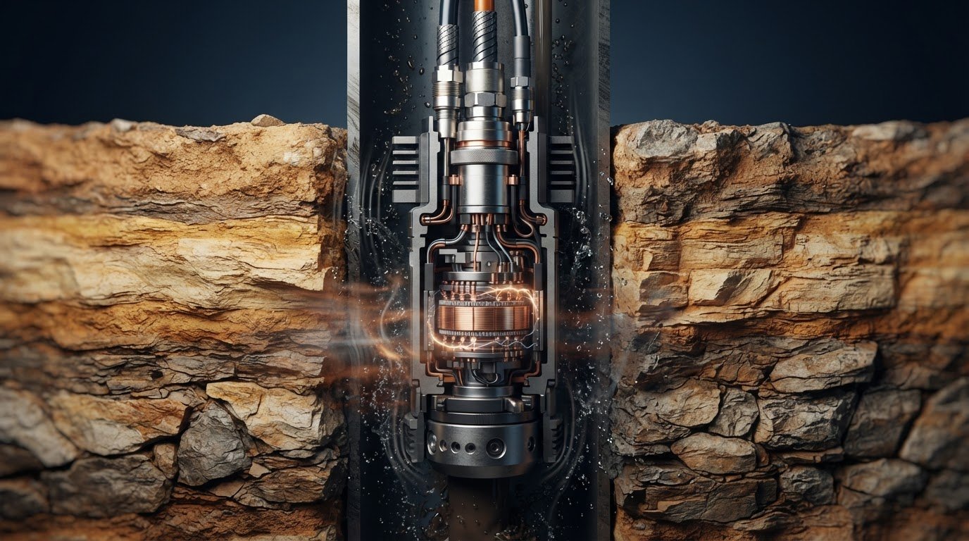
The right connector label doesn’t prove a component is suitable for downhole conditions. Selecting a rotary connector for downhole inspection tools starts with the operating envelope and the transfer job it must perform.
Temperature, pressure, fluid exposure, vibration and restricted space can all shape the selection. So can the need to transfer power, signals, data or optical signals while parts rotate. Not every rotating tool assembly needs the same type of connector.
This guide explains how to define operating requirements, compare rotary electrical connector technologies and prepare an application brief with useful technical detail. It also explains how slip ring types, including liquid metal options, differ in their stated features, without treating a product label as proof of downhole suitability. TME Systems provides technical application consulting across specialist manufacturer ranges to help match connector technology to documented application needs. A clear brief gives application engineering a practical basis for review, grounded in the tool’s conditions and transfer requirements.
Key Takeaways
- Map the tool’s motion and connection functions to determine whether it needs continuous electrical transfer during rotation.
- Build a specification from project data, recording operating cases, circuit needs and interface details in a traceable format.
- Compare a rotary connector for downhole inspection tools against documented requirements, not its product label or connector category alone.
- Use drawings, mounting details and acceptance criteria to make mechanical and environmental constraints clear before selection.
- TME Systems’ technical application consulting can help relate documented requirements to manufacturer technologies, including Prosper Rotation’s standard and custom conductive slip rings.
Rotary connector for downhole inspection tools: what must rotate?
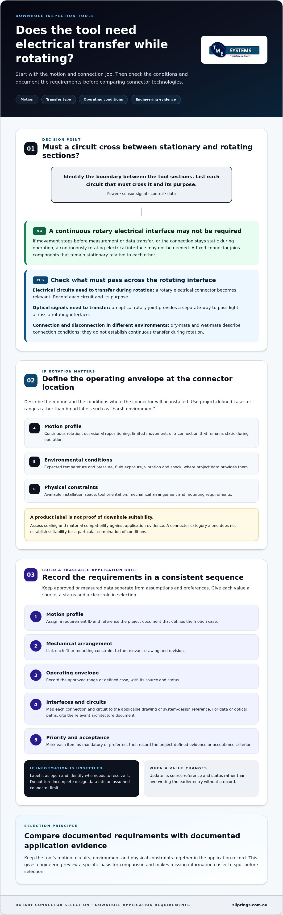
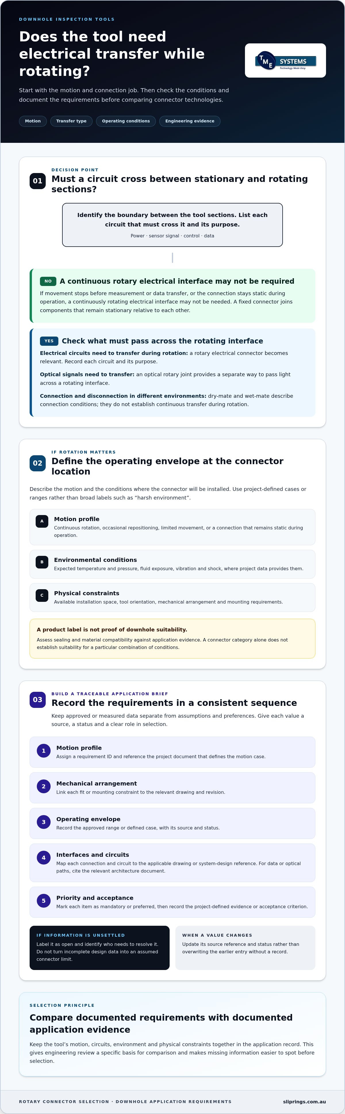
A rotary electrical connector allows power, signals or data to pass between stationary and rotating structures. The key question isn’t simply whether the tool contains a rotating part. It’s whether electrical circuits must remain connected while that part turns.
This distinction helps prevent a connector category from being mistaken for a complete application solution. A rotary interface transfers signals or power during motion. A fixed connector joins components that remain stationary relative to each other. Dry-mate and wet-mate describe connection and disconnection in different environments, but don’t establish continuous transfer during rotation. An optical connection carries light rather than electrical current, and an optical rotary joint provides a separate way to pass optical signals across a rotating interface.
When does an inspection tool need a rotary electrical connection?
Mark the tool sections that move relative to one another. For example, the outer housing might stay stationary while an internal assembly rotates, or the rotating section might carry a sensor. Identify the boundary between those sections, then list each circuit that must cross it and its purpose: power, a sensor signal, control or data. This circuit-by-circuit view clarifies what the interface needs to transfer.
Next, describe the motion. Continuous rotation with electrical transfer differs from occasional repositioning, limited movement or a connection that stays static during operation. If movement stops before measurement or data transfer, a continuously rotating electrical interface may not be required. If transfer must continue as the assembly turns, a rotary connector becomes relevant. A Rotary Steerable System provides useful context: it is designed to steer while drilling continues to rotate. That system-level function alone, however, doesn’t establish the connector requirements of an inspection tool.
Which downhole conditions shape connector selection?
Once the motion and transfer needs are clear, record the conditions at the connector location. Capture expected operating temperature and pressure, fluid exposure and available installation space. Include the rotation profile, tool orientation, vibration and shock where project data provides them. Use defined cases or operating ranges supplied by the project team instead of broad descriptions such as “harsh environment”.
Treat sealing and material compatibility as requirements to assess against application evidence, not features to assume from a connector label. The same applies to a rotary connector for downhole inspection tools: its category doesn’t establish suitability for a particular combination of conditions. Keep the tool’s motion, circuits, environment and physical constraints together in the application record. This gives engineering review a specific basis for comparison and makes missing information easier to spot before selection.
Build a downhole rotary connector specification from operating data
Turn the application inputs into a controlled specification that engineering teams can review and update. The aim is traceability: every value should have a source, a status and a clear role in selection. Keep measured or approved project data separate from assumptions and preferences, so a preliminary design note isn’t mistaken for an accepted limit.
Use a consistent sequence to organise the register, following the tool design from motion through to its interfaces and circuits:
- Motion profile: assign a requirement ID and reference the project document that defines the motion case.
- Mechanical arrangement: link each fit or mounting constraint to the relevant drawing and revision.
- Operating envelope: record the approved range or defined case, with its source and status.
- Interface and circuit needs: map each connection and circuit to the applicable drawing or system-design reference.
- Priority and acceptance: mark each item as mandatory or preferred, then record the project-defined evidence or acceptance criterion.
Keep the sequence consistent across revisions. If a value changes, update its source reference and status rather than overwriting the earlier entry without a record. This makes it easier to see which requirements changed and whether the change affects the selection decision.
Document mechanical, environmental and mounting requirements
Use established project inputs rather than recreating them from general descriptions. Give each drawing a revision identifier and note who supplied or approved the relevant information. If an input remains unsettled, label it as open and identify who needs to resolve it. This keeps incomplete design data visible without turning it into an assumed connector limit.
Define circuits, power, signals and data
Give each transfer path its own register entry, tied to the relevant system-design reference. Record the required transmission type and electrical characteristics as specified by the project. For data or optical paths, cite the relevant architecture document rather than relying on a broad label such as “communications”. The Downhole Sensors in Drilling Operations reference provides background on sensor systems, while the tool’s own documentation defines its requirements.
Register fields
Requirement: ID and category | Project value: approved range or defined case | Evidence source: document and revision | Status: mandatory, preferred or open | Acceptance: project-defined evidence
Apply the same traceability to any standard or custom option under consideration. Prosper Rotation slip rings include standard and custom conductive options. Record the specific project requirements for comparison, without treating the product category as evidence of downhole suitability.
Compare rotary connector technologies without assuming downhole ratings
Compare technologies against the tool’s required rotation and transfer function, then assess the available evidence for the operating environment and mechanical interfaces. A slip ring transfers electrical paths between rotating and stationary parts. A downhole connector may instead provide a fixed connection or allow connection and disconnection in wet or dry conditions. These functions can be part of the same tool, but they aren’t interchangeable.
Use this comparison as a starting point, not as a product rating. Distinguish each manufacturer’s stated features from evidence that a product meets the project’s temperature, pressure, fluid, vibration and installation requirements. The NASA report on slip ring experience in long-duration space applications offers a separate example of design considerations for transferring power and signals. Its application context doesn’t establish downhole suitability.
Rotary requirement: Continuous electrical transfer during rotation. Transfer type: Power, signals or data. Environment evidence: Evidence must address the project’s defined conditions. Interface constraints: Fit, mounting and circuit arrangement.
Rotary requirement: Optical transfer during rotation. Transfer type: Fibre-optic signal. Environment evidence: Assess against the tool’s operating cases. Interface constraints: Confirm the optical path and physical integration requirements.
Rotary requirement: Fixed or connect-and-disconnect interface. Transfer type: Electrical or optical, as required by the tool. Environment evidence: Review evidence for the specific connection function and environment. Interface constraints: Assess mating method, location and tool arrangement.
How do liquid metal rotary connectors differ from contact-based assemblies?
Liquid metal rotary connectors are brushless rotary connectors that use a pool of conductive liquid metal to maintain electrical continuity, eliminating wear and reducing noise. This describes a contact principle, not an application rating. Mercotac® connectors are brush-less, mercury-wetted and compact, with low resistance and low noise. Those stated features don’t establish temperature, pressure, fluid compatibility or downhole qualification. Keep each claim tied to evidence for the specific product.
Other slip-ring assemblies have different construction and manufacturer-stated characteristics. Don’t assume a feature documented for one technology or product line applies to another. For a rotary connector for downhole inspection tools, compare the transfer function and documented operating evidence rather than selecting by technology name alone.
When should electrical and fibre-optic transfer be considered separately?
Start with the instrumentation architecture. Identify which devices need electrical power or signals and which require optical transmission, then determine whether each path crosses a rotating boundary. Prosper Rotation offers fibre-optic rotary-joint options as a product category. Assess any option against the tool’s environmental and interface requirements rather than assuming the category establishes suitability. Review each transmission path against its own documented needs.
Review mounting, interfaces and engineering evidence before selection
Once the application register is assembled, review it as a controlled set of design evidence. Check that each proposed connector feature has a traceable basis and that project documents don’t conflict. Treat the review as a decision process, not another round of collecting the same inputs.
Use a simple review sequence:
- Check document control: confirm each drawing and specification has a revision or issue identifier, and note which version governs the current review.
- Trace requirements: connect each mandatory requirement to its source document and project-defined acceptance evidence.
- Compare proposals: mark which proposed features address which requirements, and identify unsupported claims or gaps.
- Resolve conflicts: record competing design constraints, the responsible decision-maker and the agreed resolution or outstanding action.
- Maintain review records: capture decisions, assumptions and changes so later design reviews can follow how the selection basis developed.
What mounting and interface information should the design team provide?
Drawings should make the proposed assembly and connection points legible, with the relevant revision clearly identified. Use the drawing set to check that the selected arrangement is consistent across the tool design, rather than treating one isolated view as definitive. If two drawings show different interface details, record the discrepancy and send it to the design owner for resolution before treating either version as approved.
Keep supporting evidence distinct from the drawing package. A drawing establishes design geometry; operating records and system documents support other requirement types. A traceable reference to each source lets application engineering assess a proposal without silently filling gaps. The Slip Ring Application Engineering reference provides broader selection context for this review.
What should a final engineering review resolve?
Check whether each proposed feature is supported by product-specific information and whether that evidence addresses the relevant requirement. Record any mismatch as an open engineering item, with an owner and a decision needed. Don’t convert a general product description into proof for an unaddressed project condition. Keep verification tests and acceptance criteria tied to the project’s defined review process, rather than introducing unapproved thresholds.
Application engineering can help make trade-offs visible when design constraints compete. The review should show which requirements drive the decision, which evidence supports the proposed approach and what remains unresolved. To discuss the application with TME Systems, request technical application consulting.
Match downhole inspection requirements to a rotary connector solution
Once the application brief is assembled, match its documented needs with manufacturer technologies. TME Systems provides technical application consulting across Mercotac®, Meridian Laboratory (ROTOCON), BGB Innovation and Prosper Rotation. This gives the selection process access to multiple specialist ranges, while keeping each manufacturer’s stated features distinct. A product category or general application description is a starting point for review, not evidence that a connector is rated for a particular downhole tool.
How can a multi-manufacturer range support application-led selection?
Compare each range against the tool’s transfer paths, physical arrangement and project operating conditions. Mercotac® connectors are brush-less, mercury-wetted and compact, with low resistance and low noise. Meridian Laboratory (ROTOCON) connectors are brush-less and support high-current, high-speed and through-bore applications, including harsh environments. These are distinct stated strengths, not interchangeable specifications. BGB Innovation assemblies cover power, signal, data, wind-turbine, water-treatment and custom rotary-engineering uses. Let the project brief guide consideration of the range.
Prosper Rotation offers standard and custom conductive slip-ring options. A standard option can be compared with a defined requirement set, while a custom option provides a path for application-specific requirements. Neither description establishes suitability for downhole conditions; assess any proposed configuration against project evidence. The Prosper Rotation slip rings range is one part of this wider, requirements-led comparison.
What information should accompany an application enquiry?
Give application engineering enough context to relate the proposed connector architecture to the tool, not just a list of preferred features. The Slip Ring Application Engineering reference provides broader background to selection. Prepare the following for a focused technical discussion:
- Tool function: explain what the inspection tool measures or controls and where the rotary interface sits in the assembly.
- Motion profile: describe the direction, rotation pattern and duty requirements using project data.
- Mechanical information: attach mounting and mating-interface drawings, identifying the available envelope and adjacent component constraints.
- Transfer requirements: list circuit count and the purpose of each electrical or optical path, including relevant system-design characteristics.
- Operating conditions: provide documented temperature, pressure, fluid exposure and other defined environmental cases.
- Open inputs: distinguish approved values from estimates, preferences and unresolved design questions.
This information helps TME Systems’ technical application consulting compare documented requirements with the stated capabilities of its manufacturer ranges. Share the tool drawings, circuit needs and operating conditions to begin a focused application discussion. The result is a technically grounded selection path, with remaining evidence needs identified rather than assumed.
Turn the application brief into a clear next step
Carry the selection rationale forward as the inspection tool moves through design review. A clear record of why a rotary connector was considered helps the team reassess the decision if the tool’s function or architecture changes. It keeps connector selection tied to design intent, rather than allowing an early assumption to become an unexamined part of the final assembly.
With the selection basis documented, the next design conversation can focus on decisions specific to the tool. A careful, evidence-led approach gives the project a sound path forward. Contact TME Systems to discuss your application and request technical application consulting.
Frequently Asked Questions
Can a standard industrial slip ring be used in a downhole inspection tool?
Possibly, but an industrial description alone doesn’t establish suitability for downhole service. Compare product-specific evidence with the tool’s defined conditions, including pressure, temperature, fluid exposure, rotation and mounting. For example, a unit described as suitable for harsh environments still needs evidence relevant to the fluids and operating cases in your design. Treat any gap between the project requirement and available evidence as an engineering issue to resolve, not an assumed match.
What is the difference between a downhole connector and a rotary connector?
A downhole connector provides an electrical or optical connection for downhole use; a rotary connector transfers power, signals or data between stationary and rotating parts. A tool may need both, such as a rotary interface within an assembly and a separate connection at a tool boundary. Map each connection point and its function. This helps prevent specifying a rotary component where a fixed connection is needed, or overlooking rotation where circuits must remain connected.
Can a rotary connector carry data as well as power?
Yes. Depending on the model and application, slip rings can carry power, control signals, Ethernet, fieldbus, analogue signals or fibre-optic signals. For example, an inspection system might power a sensor while sending its output through the rotating interface. Specify the required data type and relevant system characteristics rather than writing only “data”. Then compare those needs with the published capabilities of the specific connector model.
How do I specify a rotary connector for downhole inspection tools?
Start with the tool’s function and identify which signals or supplies cross the rotating boundary. For a rotary connector for downhole inspection tools, use project drawings and system-design data to record operating cases, interface geometry and electrical or optical needs. Mark each value as approved, provisional or unresolved. This distinction helps application engineering focus on genuine design gaps and prevents an assumed value from being treated as a project requirement.
Are liquid metal rotary connectors automatically suitable for downhole use?
No. Liquid metal describes a contact technology, not a qualification for a particular downhole environment. A stated electrical characteristic doesn’t establish performance under the tool’s pressure, temperature, fluid exposure or sealing conditions. Review evidence for the specific product against each project requirement. For liquid-metal designs, material compatibility is also a relevant engineering question, since the contact medium and surrounding materials need assessment for the intended application.
Can TME Systems supply custom slip rings for a specific inspection tool?
Yes. TME Systems works with manufacturers that offer standard and customised slip-ring solutions. Technical application consulting helps relate the project brief to available manufacturer technologies, rather than assuming one range fits every requirement. For example, a design with an unusual interface or combined transfer needs can be presented with its drawings and system requirements for application-led consideration. Product features remain specific to the manufacturer and option being assessed.
What information should I provide for a rotary connector application review?
Provide a short description of the tool’s function, its mechanical drawings and the required power, signal, data or optical paths. Include the rotation pattern and operating cases from the project design. If electrical values or environmental limits are still being finalised, label them as open inputs rather than leaving their status unclear. This gives the application review a practical starting point and distinguishes established requirements from decisions still in progress.