Could a rotary connection that appears suitable on paper still compromise the current return path once the workpiece starts turning? Choosing a rotary ground for circular welding applications means looking beyond current rating alone. The rotating assembly, operating duty and mounting arrangement all affect the specification. An unsuitable or unstable connection can contribute to inconsistent welding.
Start with the current transfer requirements, then consider how the machine rotates and operates. This guide explains the role of rotary grounding and compares contact-based and liquid metal approaches against application requirements. It also outlines the technical details that help turn a machine layout and duty cycle into a useful engineering review.
Factors to assess include welding current, rotational speed, duty cycle, available space, mounting and operating conditions. These details help distinguish between rotary connection options, including Prosper Rotation slip rings, without assuming one configuration suits every welding system. TME Systems provides technical application consulting to help assess requirements and define a suitable rotary electrical connector specification.
Key Takeaways
- Assess a rotary ground for circular welding applications against the full operating duty, not current rating alone.
- Distinguish the welding-current return connection from protective earthing when mapping the electrical arrangement.
- Compare conventional slip rings, collector rings and liquid metal technology by their operating principles and application requirements.
- Prepare for an engineering review by documenting the electrical duty, rotation, environment, shaft layout and mounting interfaces.
- Use technical application consulting to translate system requirements into a rotary connector specification.
What rotary ground does in a circular welding application
A rotary ground provides the electrical return connection between a rotating workpiece and the stationary part of a welding circuit. It may form part of a rotary electrical joint or use slip-ring technology, providing a path for welding current to return to the power source while the assembly turns. A slip ring is an electromechanical device that transfers electrical connections between stationary and rotating components.
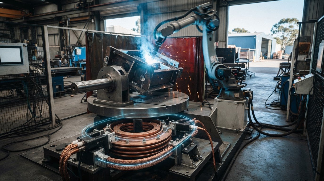
In a typical circuit, current travels from the welding power source along the welding lead to the electrode, crosses the arc to the workpiece, then flows through the return path back to the source. During circular welding, the workpiece or its fixture rotates while the power source and some cabling remain stationary. The rotary connection bridges those moving and fixed parts, helping maintain electrical continuity without winding the welding lead around the rotating assembly.
How the welding return path behaves during rotation
The arrangement depends on the machine. A positioner may rotate the workpiece while the torch stays in place, or the welding head and its support may move around a stationary component. In either case, identify which parts rotate and where the return current must cross between moving and stationary components. The rotary connection supports that path, but cannot by itself guarantee a particular weld result.
Selection depends on the complete application. Welding current matters, but so do duty cycle, rotation conditions and the assembly’s mechanical layout. A connector chosen without these details may not suit the operating demands, even if its current rating appears adequate.
Rotary ground versus protective earthing
The welding return circuit carries welding current between the workpiece and the power source. Protective earthing has a different role: it relates to electrical safety and is not a substitute for the welding return connection. Treating the two as interchangeable can lead to an incorrect system design.
AS/NZS 3000:2018 is the Australian/New Zealand wiring rules standard for electrical installations. Its role should not be confused with specifying a rotary welding return arrangement. This guide doesn’t replace qualified electrical design or installation advice. For a rotary ground for circular welding applications, define the circuit function and operating conditions as part of the engineering assessment.
Which electrical and mechanical requirements shape rotary ground selection?
Start with the operating brief, not a catalogue rating. A rotary ground for circular welding applications must be assessed against the electrical load, machine movement and conditions around the rotating assembly. Current and voltage are core inputs, but nominal current alone doesn’t describe how the connector will operate across a production cycle.
Electrical load, duty cycle and thermal management
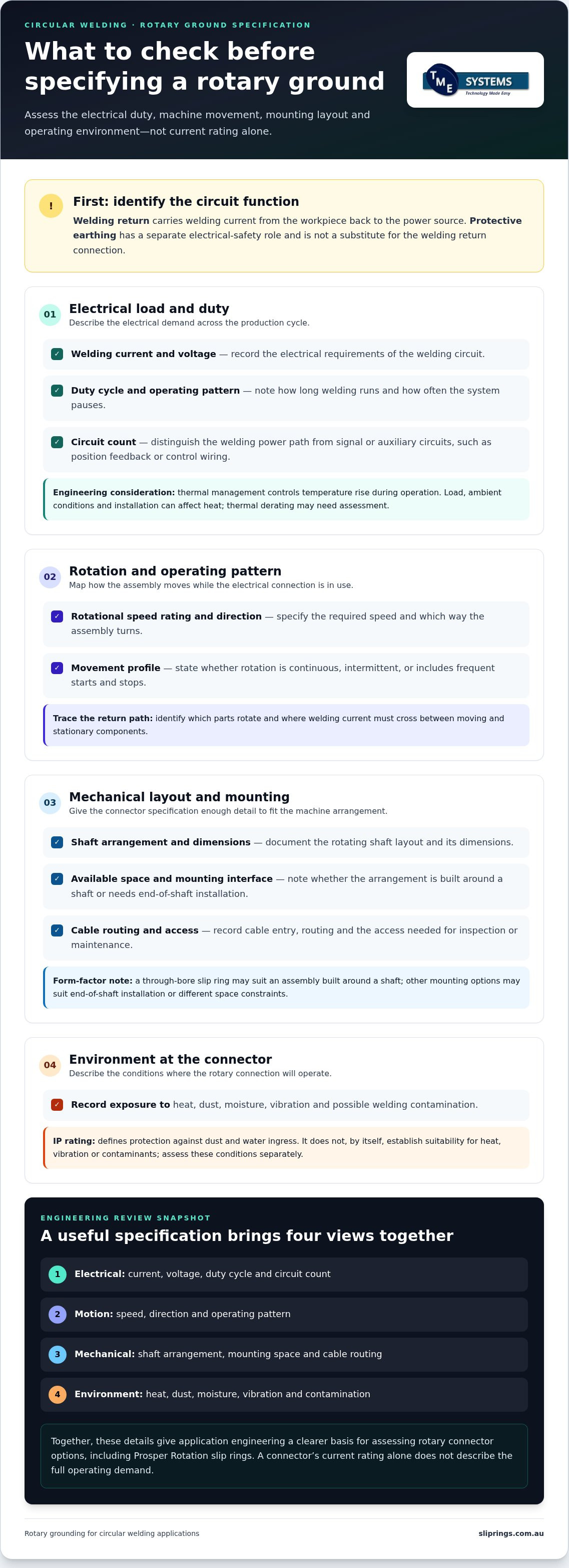
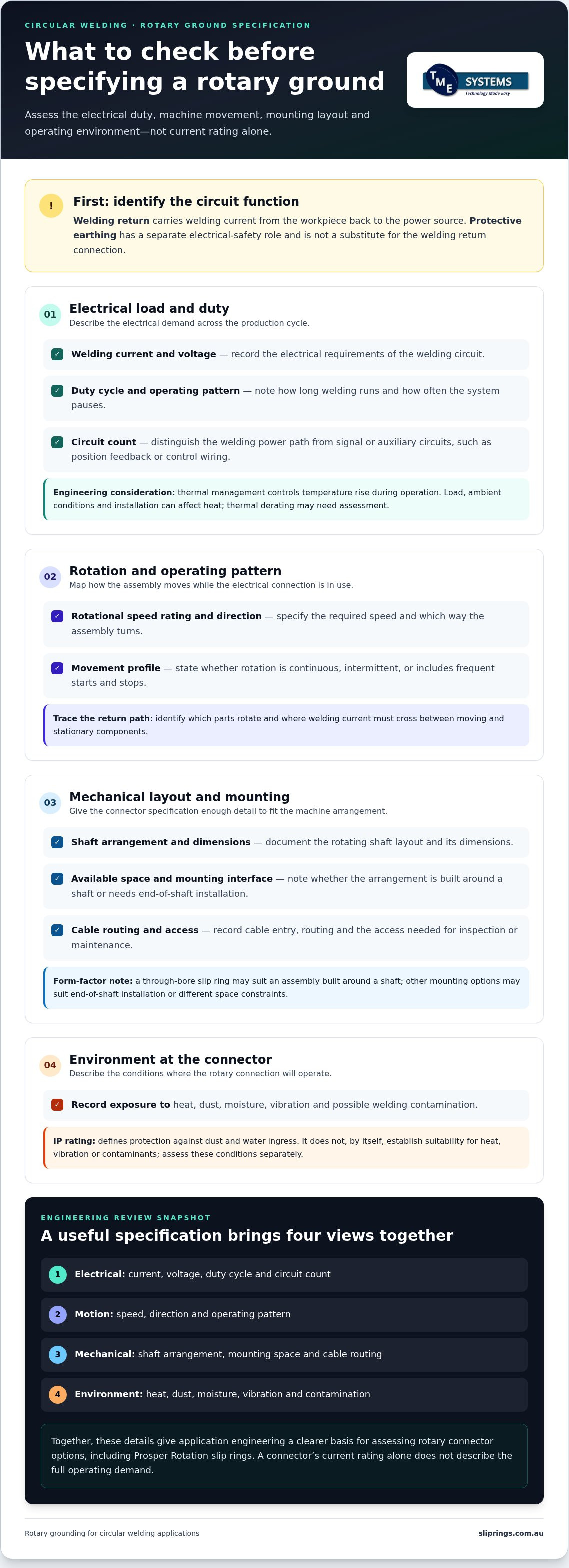
Record the welding current and voltage, duty cycle and expected operating pattern, including how long welding runs and how often the system pauses. These details help define the electrical load over time. Thermal management means controlling temperature rise during operation. Heat can be affected by the load, ambient conditions and connector installation, so thermal derating, the reduction of allowable current when conditions increase temperature, may need to be considered in the engineering assessment.
Also state the required circuit count. Separate the welding power path from signal or auxiliary circuits, such as position feedback or control wiring. This prevents the specification from treating all electrical paths as interchangeable. For additional background on welding equipment grounding, consult the American Welding Society’s Grounding of Portable and Vehicle Mounted Welding Generators fact sheet.
Rotation, mounting and operating environment
Document the required rotational speed rating, direction of rotation, and whether movement is continuous, intermittent or includes frequent starts and stops. A through-bore slip ring may suit an assembly built around a shaft. Other mounting options may fit end-of-shaft installation or different space constraints. Record shaft dimensions, available mounting space, cable entry and routing, and access needed for inspection or maintenance.
Describe the environment at the connector location, not just the general workshop. Note heat, dust, moisture, vibration and possible exposure to welding contamination. An IP rating defines protection against dust and water ingress; it doesn’t by itself establish suitability for heat, vibration or contaminants. Assess those conditions separately.
- Electrical: current, voltage, duty cycle and circuit count.
- Motion: speed, direction and operating pattern.
- Mechanical: shaft arrangement, mounting space and cable routing.
- Environment: heat, dust, moisture, vibration and contamination.
These inputs give application engineering a clear basis for matching a rotary connector to the machine. For example, Prosper Rotation slip rings can be assessed against the documented requirements rather than selected on the basis of a single rating.
Comparing rotary connection approaches for circular welding
Rotary connections differ in how they transfer current between stationary and rotating components. Conventional slip rings commonly use sliding electrical contacts. Collector rings are designed for heavy-duty rotary connections, while liquid metal technology uses conductive liquid metal to form the electrical path. None is automatically the right choice for a welding return circuit. Assess the required current, duty cycle, speed, mounting and environment against the specific configuration and its product data.
The distinction in collector ring vs slip ring is functional, not a universal ranking. A collector ring may suit an application calling for a heavy-duty rotary connector, while a conventional slip-ring arrangement may suit a different circuit and mechanical configuration. Review contact design and application specifications rather than relying on the category name. BGB Innovation slip rings are another product range to consider when assessing rotary connection options.
| Selection factor | Conventional slip ring | Collector ring | Liquid metal technology |
|---|---|---|---|
| Current and voltage | Check rated values for the exact configuration. | Verify capacity and voltage from product data. | Confirm suitability for the required electrical load. |
| Duty cycle | Compare the operating pattern with specified limits. | Assess against the intended duty and contact design. | Check product data for the application’s duty. |
| Speed | Match operating speed to the rotational speed rating. | Verify the rating for the required motion. | Confirm rated speed for the specific connector. |
| Mounting | Check shaft, space, cable and mounting interfaces. | Check fit with the rotating assembly and supports. | Confirm available form and mounting arrangement. |
| Environment | Review protection and operating limits. | Assess dust, moisture, heat, vibration and contamination. | Check sealing and environmental specifications. |
| Circuit count | Confirm separate power, signal and auxiliary paths. | Specify the required independent paths. | Verify circuit configuration and intended function. |
Where liquid metal technology fits
Liquid metal technology is a contact method that uses a pool of conductive liquid metal to provide an electrical path. Liquid metal rotary connectors are brushless, but that description alone doesn’t establish their current capacity or suitability for welding. Confirm the product’s circuit, electrical and operating specifications. Use “mercury-free liquid metal” only when the relevant product specification supports that description.
For an Australian application, treat overseas material as background rather than local compliance advice. The US OSHA standards for welding ground returns are jurisdiction-specific and do not establish Australian requirements. Compare documented product data with the complete machine specification when assessing a rotary ground for circular welding applications.
How to prepare a rotary ground specification for engineering review
A useful application brief turns the machine’s operating conditions into information that can be compared with rotary connector specifications. Work through the assembly in sequence: map what rotates, document the electrical duty, record motion and environment, then check mounting and cable interfaces. This gives an engineering review a clear basis for assessing a rotary ground for circular welding applications.
Information to include in the application brief
Include a machine drawing where available, or a clear description of the assembly. Show the shaft, workpiece, fixture, welding head, rotating components, available mounting space and cable entry points. Mark the proposed rotary connection location and note physical obstructions or access requirements.
- Electrical duty: welding current and voltage, duty cycle, circuit count, and any signal or auxiliary circuits.
- Process and motion: welding process, workpiece and fixture details, which assembly rotates, rotational speed, direction, and whether movement is continuous or intermittent.
- Installation conditions: ambient conditions, heat, dust, moisture, vibration, welding contamination, cable routing and connection constraints.
Separate confirmed values from assumptions. Label estimates, unknowns and operating conditions that haven’t been measured rather than presenting them as fixed requirements. For example, distinguish a documented operating speed from an estimate based on a machine setting. This helps focus the review on information that may affect connector selection.
How application engineering narrows the options
TME Systems’ technical application consulting assesses rotary connector categories against the stated electrical, speed, mounting and environmental requirements. The review compares application needs with available product specifications and identifies where the information supports a suitable match or where further engineering detail is needed. This avoids selecting a slip-ring type based on one rating alone.
AS/NZS 5368:2025 concerns electrical equipment in mines and quarries. Its relevance depends on the specific application and operating context, so it shouldn’t be treated as a general rotary-ground specification or as evidence of product compliance for a welding system.
For a practical review, provide the drawing or layout description alongside the electrical and operating data. The Prosper Rotation slip-ring range is one option to assess against those requirements.
Choosing a rotary ground solution for your circular welding system
Use the application brief to identify which rotary connector type aligns with the machine’s electrical duty and mechanical layout. For a rotary ground for circular welding applications, prioritise electrical load and duty cycle. Then compare available configurations against rotational speed, mounting, circuit requirements and operating environment. A product category or headline rating alone can’t establish suitability.
Decision framework: match the solution to the duty
Work through the requirements in order. Confirm current, voltage and duty cycle, then check that the connector’s documented specifications match the operating speed and motion. Assess shaft interfaces, mounting space, cable routing and environmental conditions against the proposed configuration. This keeps the decision focused on technical fit before secondary features.
A standard configuration may suit the application if its documented electrical and mechanical specifications meet the brief. A tailored arrangement may be appropriate where the assembly or interfaces call for a different configuration. In either case, compare the actual requirements with product data and record any unresolved assumptions. An engineering review can then address those points directly instead of treating estimates as confirmed operating conditions.
Next steps with TME Systems
TME Systems provides technical application consulting to assess industrial rotary connectors against circuit, electrical, speed, mounting and environmental requirements. Prepare a concise description of the welding system, its electrical duty and the arrangement of the rotating assembly. Drawings or a layout sketch can clarify shaft position, available space, cable entry and nearby components.
A final engineering review assesses the fit between the stated requirements and relevant product specifications. This supports a reasoned selection without assuming that one connector type suits every circular welding system.
- Application description, welding process and workpiece or fixture layout.
- Current, voltage, duty cycle, circuit count and any signal requirements.
- Rotation details, including speed, direction and operating pattern.
- Mounting dimensions, shaft arrangement, cable entry and available space.
- Environmental conditions and any values that are estimates or still unknown.
With those details ready, discuss your rotary connector application with TME Systems and explore the Prosper Rotation slip-ring range as part of the selection process.
Put the application requirements into a clear specification
Selecting a rotary ground for circular welding applications starts with the complete operating brief, not a current rating in isolation. Electrical load and duty cycle guide the assessment, while rotational speed, mounting arrangement, circuit needs and environmental conditions help narrow the connector options. A clear drawing and labelled assumptions also make an engineering review more useful.
Conventional slip rings, collector rings and liquid metal technology have different operating principles. Compare them against documented specifications and the actual machine layout rather than treating one approach as a universal choice. The right technical fit depends on how the welding system operates and how the connector must integrate with its rotating assembly.
TME Systems’ technical application consulting helps assess industrial slip-ring options against electrical, speed, mounting and environmental requirements. Prepare the application description, electrical duty and mounting information, then discuss your rotary connector application with TME Systems.
Frequently Asked Questions
What is a rotary ground in circular welding?
A rotary ground is the rotating electrical return connection between the workpiece and the welding power source. In a circular welding setup, it provides a current path between rotating and stationary parts of the assembly. The welding circuit includes the power source, welding lead, electrode, workpiece and return path. Connector selection depends on the specified electrical load, duty cycle, rotation and mounting arrangement.
Can a standard slip ring be used as a welding ground?
A standard slip ring may be considered only if its documented specifications suit the welding return duty and machine arrangement. Check the required current and voltage, duty cycle, rotational speed, contact design, circuit configuration and operating environment. A rating in one area doesn’t establish suitability for the complete application. Review product data against the machine requirements as part of an engineering selection process.
How do I choose a rotary ground for a welding positioner?
Choose a rotary ground for a welding positioner by matching the connector to the electrical duty and the positioner’s movement and layout. Document current, voltage, duty cycle, speed, direction of rotation and whether operation is continuous or intermittent. Include shaft details, mounting space, cable entry and environmental conditions. These inputs help technical application consulting assess connector categories against the actual application.
What is the difference between a rotary ground and protective earthing?
A rotary ground carries welding current through the return circuit between the workpiece and the power source. Protective earthing serves an electrical safety function, so it isn’t a substitute for the welding return path. The two functions need to be distinguished in system design. AS/NZS 3000:2018 is the Australian/New Zealand wiring rules standard for electrical installations; this guide isn’t a replacement for qualified electrical design.
Which details affect rotary ground performance during welding?
Electrical load, duty cycle and operating pattern affect the demands placed on a rotary connection. Rotation speed and direction, mounting, shaft arrangement, cable routing and circuit count also shape selection. Record site conditions such as heat, dust, moisture, vibration and welding contamination. An IP rating describes protection against dust and water ingress, but doesn’t establish suitability for every environmental condition.
Can liquid metal rotary connectors be used for circular welding applications?
Liquid metal rotary connectors use a pool of conductive liquid metal to maintain electrical continuity without brush contacts. Whether a specific connector can serve in a circular welding return circuit depends on its documented current, voltage, duty cycle, speed, mounting and environmental specifications. The technology description alone doesn’t establish welding suitability. Compare verified product data with the full application requirements during engineering review.
What information should I provide for a rotary ground engineering review?
Provide an assembly drawing or clear layout description showing the shaft, workpiece, fixture, rotating components, mounting space and cable entry. Include welding current, voltage, duty cycle, rotational speed, circuit count and any signal requirements. Describe the welding process and operating environment, too. Label estimates and unknown conditions separately from measured values so the review can address assumptions directly.