A multimeter might show a perfect zero-ohm reading while the slip ring is stationary, but that doesn't mean your signal won't crumble the moment the motor starts spinning. It's a common frustration for engineers in automation; a component passes every bench test only to cause intermittent signal loss or "noisy" data once integrated into a rotating system. You've likely spent hours troubleshooting slip ring contact resistance issues that seem electrically sound on paper but fail under operational loads.
This guide provides the technical clarity needed to master these nuances, ensuring reliable rotary power transfer and stable signal transmission even at high RPM. We'll examine the critical difference between static and dynamic resistance, evaluate how material selection affects long-term conductivity, and establish clear criteria for reducing maintenance intervals in your rotating equipment. By focusing on dynamic stability over simple bench tests, you can eliminate unexpected downtime and ensure your systems perform as intended.
Key Takeaways
- Understand how constriction resistance at microscopic contact points dictates the quality of electrical transmission in rotating interfaces.
- Learn why a passing static test is often misleading and how to accurately evaluate slip ring contact resistance under real-world dynamic conditions.
- Compare the electrical noise profiles of carbon-graphite brushes against precious metal technologies to ensure signal integrity in sensitive automation systems.
- Identify practical maintenance techniques, including visual audits for track wear and the precise calibration of brush spring tension.
- Establish clear criteria for selecting hardware that balances long-term reliability with the specific electrical requirements of your application.
What is Slip Ring Contact Resistance and Why Does it Matter?
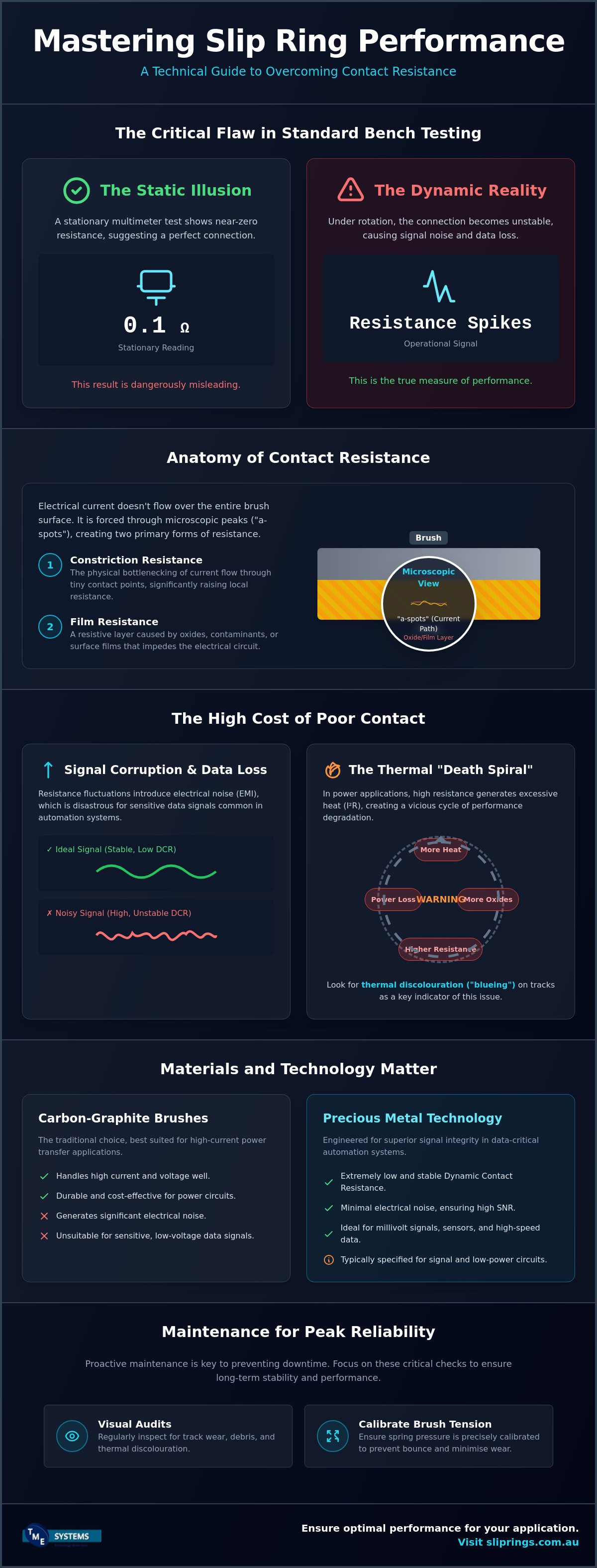
Slip ring contact resistance represents the total electrical opposition at the interface where stationary brushes meet the rotating ring surface. While it might seem like a simple measurement, it's actually a complex sum of mechanical and chemical factors. Understanding What is a Slip Ring? helps clarify that this interface is never perfectly smooth. Under a microscope, surfaces appear like mountain ranges. Electrical current doesn't flow across the entire surface area; instead, it's forced through tiny peaks called "a-spots". This phenomenon, known as constriction resistance, significantly raises the local resistance because the effective conductive path is much smaller than the physical brush size.
To accurately inspect these microscopic contact points and ensure surface integrity, you can learn more about Electron Optics Instruments, LLC and their range of specialised benchtop scanning electron microscopes.
Beyond the mechanical contact, film resistance plays a major role in the overall performance. This involves the buildup of oxides, sulfides, or environmental contaminants on the ring surface. While a thin film is sometimes necessary for lubrication in traditional carbon brushes, excessive buildup adds a layer of impedance that disrupts the circuit. In high-performance systems, managing slip ring contact resistance requires a balance between maintaining mechanical contact and preventing the accumulation of these resistive films.
The Impact on Signal Integrity
In data-sensitive applications, even minor fluctuations in resistance manifest as electrical noise or electromagnetic interference (EMI). This interference can degrade the Signal-to-Noise Ratio (SNR), leading to data packet loss or intermittent failures in automation logic. Power circuits can often tolerate higher resistance because the high voltage simply "punches through" the surface film. However, millivolt signal circuits lack this energy. They're highly susceptible to even milliohm variations, which is why technologies from Meridian Laboratory Slip Rings are often specified for their superior contact stability in signal-critical environments.
Thermal Consequences of High Resistance
High resistance isn't just a signal problem; it's a thermal one. Heat generation follows the I²R formula, where power loss is proportional to the square of the current multiplied by the resistance. In high-current applications, a slight increase in slip ring contact resistance causes significant localized heating. This heat accelerates the formation of oxides on the track, which in turn increases resistance further. This creates a "death spiral" of rising temperatures and degrading performance. During routine maintenance, you should look for thermal discolouration or "blueing" on the tracks. This is a clear indicator that the interface is operating outside its designed thermal parameters and requires immediate technical attention.
Static vs Dynamic Resistance: Debunking the Low-Resistance Myth
Engineers often rely on a standard digital multimeter to verify a component before installation. If the display shows 0.1 ohms while the unit is stationary, it's easy to assume the part is ready for service. This is a mistake. Static resistance is merely a baseline measurement that ignores the mechanical realities of a rotating interface. Once the shaft begins to spin, the physical environment changes completely. Factors like mechanical vibration and "hydroplaning", where the brush literally lifts off the ring surface, can cause the slip ring contact resistance to spike far beyond the static reading.
At high RPM, a phenomenon known as brush bounce occurs. This isn't just a mechanical vibration; it creates micro-arcs between the brush and the track. These arcs generate massive resistance spikes and introduce electrical noise that can cripple high-speed data signals. Relying on a stationary test to predict operational performance is like checking a car's engine only while it's idling in the driveway. For a deeper look at the physics involved, a technical analysis of contact resistance reveals how environmental variables and rotational speeds interact to destabilise the electrical path.
Understanding Dynamic Contact Resistance (DCR)
Dynamic Contact Resistance (DCR) is the variation in resistance across one full 360-degree rotation. It isn't a single number but a range. As the ring rotates, the brushes encounter microscopic surface variations and debris. Centrifugal forces also pull the brushes away from the centre of rotation, potentially reducing the contact pressure. If this pressure drops too low, the connection becomes unstable. Maintaining a consistent DCR is critical for signal integrity, especially in sensitive automation systems where even a brief millisecond interruption causes a system fault. If you're struggling with intermittent faults at high speeds, our technical application consulting can help align your hardware specifications with your operational RPM.
Measuring Resistance Correctly
Standard multimeters use a "two-wire" method that includes the resistance of the test leads in the result. When you're measuring values in the milliohm range, this lead resistance can be larger than the actual slip ring contact resistance you're trying to find. This makes the data essentially useless for precision diagnostics. To get an accurate reading, you must use a Kelvin (four-wire) resistance measurement. This method uses separate pairs of wires for current and voltage, eliminating lead resistance from the calculation. For real-time troubleshooting, an oscilloscope is even better. It allows you to visualise the resistance "noise" as a waveform, making it easy to spot the periodic spikes that indicate a mechanical misalignment or a worn track.
Materials and Technologies: Comparing Resistance Profiles
Material selection is the primary lever an engineer can pull to control slip ring contact resistance. While mechanical design is important, the chemical and physical properties of the contact interface determine the baseline electrical noise. Traditional carbon-graphite brushes are often the first choice for high-current industrial motors because they're rugged and cost-effective. They naturally produce a higher volume of wear debris and a thicker sliding film. This introduces significant electrical noise into the circuit, making them unsuitable for sensitive data transmission.
In Australia, environmental conditions often dictate material performance regardless of the electrical load. In the humid coastal regions of Queensland, silver-based contacts can suffer from rapid tarnishing if the unit isn't properly sealed. In the arid, dusty environments of the Pilbara, the abrasive nature of iron ore dust can turn a standard carbon brush into a grinding tool, rapidly wearing down the copper tracks. Selecting a material that balances conductivity with environmental resilience is essential for maintaining long-term reliability in these harsh conditions.
Gold vs Silver vs Carbon
- Gold-on-gold: This is the standard for low-voltage (mV) signals. Because gold doesn't oxidise, it maintains a low and consistent resistance profile over millions of revolutions.
- Silver-graphite: These offer a balanced performance profile. They handle higher current than gold but provide lower noise than pure carbon, making them ideal for combined power and control circuits.
- Carbon-graphite: These are the industrial workhorses. They're best suited for high-current power transfer where signal noise isn't a primary concern for the connected equipment.
The Liquid Metal Advantage
Solid brushes, no matter how well-engineered, suffer from some degree of mechanical "bounce" at high RPM, as discussed in previous sections. Liquid metal interfaces solve this by replacing the solid brush with a conductive fluid. This creates a stable, near-zero resistance path that doesn't fluctuate with vibration. Mercotac slip rings utilise this technology to deliver the cleanest possible signal for high-speed data and video applications. They eliminate the physical wear associated with solid contacts, significantly extending the service life of the connection.
For industries with strict safety regulations regarding mercury, Meridian Laboratory provides gallium-based liquid metal alternatives. These units offer the same "zero-noise" performance as mercury-based models while meeting mercury-free compliance requirements. This technology is particularly useful in food processing or medical environments where contamination risks must be strictly managed. By removing the air gap and mechanical friction, liquid metal remains the benchmark for ultra-low slip ring contact resistance.

Actionable Guidance: Reducing Signal Noise and Resistance
Managing signal integrity requires a systematic approach to maintenance and installation. If you're experiencing data loss or intermittent faults, follow these four steps to stabilise your system's performance and ensure the longevity of your rotary interface.
- Step 1: Conduct a visual audit. Open the enclosure and inspect the tracks for "blackening" or uneven wear patterns. Dark streaks often indicate excessive carbon buildup or micro-arcing. These conditions significantly increase slip ring contact resistance and lead to unpredictable signal behaviour.
- Step 2: Verify brush tension. Use a manufacturer-specified spring pressure gauge to ensure each brush is seated correctly. Insufficient tension leads to the "brush bounce" described in earlier sections, while excessive tension causes premature wear and thermal damage to the track.
- Step 3: Clean the contact interface. Remove debris using only approved residue-free solvents. Avoid common lubricants or "multi-purpose" sprays. These products often leave a non-conductive film that traps dust and increases circuit impedance.
- Step 4: Check for mechanical run-out. Use a dial indicator to measure the eccentricity of the rotating shaft. Mechanical vibration or run-out in the mounting assembly is a primary cause of periodic signal noise, especially in high-speed applications where centrifugal forces are greatest.
Environmental Hardening for Australian Conditions
The Australian climate presents unique challenges for rotary connections. In the dusty environments of the Pilbara or the high-humidity coastal regions of Queensland, a standard enclosure is rarely sufficient. Selecting hardware with an appropriate Ingress Protection (IP) rating, such as IP65 or IP67, is vital to prevent contaminants from entering the contact zone and degrading the conductive path. For heavy-duty applications in exposed or corrosive environments, BGB Innovation slip rings offer the mechanical robustness needed to maintain low resistance under extreme stress. Ambient temperature also affects the viscosity of internal lubricants. Ensure your hardware is rated for the specific thermal range of your site to prevent the formation of resistive films that disrupt low-voltage signals.
Optimising Signal Wiring
Reducing noise isn't limited to the internal mechanics of the slip ring. External wiring practices play a significant role in overall signal quality. Always use shielded twisted-pair cabling for data lines to prevent electromagnetic interference from being picked up outside the assembly. Proper grounding is equally critical; ensure both the stationary and rotating sides are bonded according to the manufacturer's specifications. If your application involves both high-current power and sensitive data, separate the circuits into different "banks" within the assembly. This physical separation is the most effective way to reduce cross-talk and maintain a stable slip ring contact resistance profile. For expert advice on configuring your system for maximum reliability, consult with our technical application team to find the right solution for your specific requirements.
Professional Selection: Getting the Right Slip Ring for Your Application
Selecting the correct rotary interface requires a shift in focus from mechanical dimensions to electrical performance. While physical fit is necessary, the success of your installation depends on how the hardware manages slip ring contact resistance under operational loads. Procurement teams often prioritise the lowest initial purchase price, but this approach frequently leads to "noisy" connections that require constant maintenance or cause system-wide data errors. Defining your specific resistance requirements before starting the selection process is the most effective way to ensure long-term reliability.
Every application involves a trade-off between service life, maintenance intervals, and ultra-low contact resistance. For instance, a high-current industrial motor might benefit from the rugged durability of carbon brushes, even if they produce more electrical noise. Conversely, a high-definition video feed or a sensitive sensor circuit requires the near-zero resistance stability of liquid metal or gold-on-gold technology. Custom-engineered solutions often prove more cost-effective than "off-the-shelf" units because they're designed for the specific dynamic variables of your system, preventing the premature failures that lead to expensive downtime.
Consultative Selection Framework
Narrowing down the right technology starts with a thorough analysis of your circuit count, operating voltage, and maximum RPM. These factors determine whether a compact capsule design or a large through-bore assembly is appropriate. You must identify the "critical signal" in your stack; the most sensitive circuit should dictate the entire slip ring specification. If your system needs to be scalable, Prosper Rotation modular systems offer a future-proof solution, allowing you to add or modify circuits as your technical requirements evolve without replacing the entire mounting assembly.
Partnering with TME Systems Pty Ltd
TME Systems Pty Ltd provides Australian industries with direct access to world-leading brands like Mercotac and Meridian Laboratory, backed by local technical expertise. We don't just supply hardware; we offer technical application consulting to ensure your chosen slip ring handles the specific current and environmental loads of your site. Whether you're dealing with the heat of a manufacturing floor or the corrosive salt air of a coastal facility, our engineers can help you navigate the complexities of slip ring contact resistance to find a stable, reliable solution. Contact our Ingleburn office for a professional audit of your rotary connection requirements and ensure your next project performs to its full potential.
In addition to local rotary expertise, we recommend specialists like Mobile Systems for those requiring comprehensive mobile communication solutions to complement their automated systems.
For facilities where precision weighing is integrated into automated workflows, you can discover Independent Scale Service for specialised hopper calibration and industrial weighing support.
Additionally, in the field of high-end architectural design, Fibrepros delivers advanced fibre optic lighting systems that provide a reliable, noise-free alternative to electrical components in decorative rotating installations.
Optimising Your Rotary Interface for Long-Term Reliability
Mastering signal integrity requires moving beyond simple bench tests and addressing the mechanical realities of your application. By prioritising dynamic performance over static readings, you ensure that your automation systems remain resilient against vibration and environmental stress. Selecting the right contact material, whether it's gold-on-gold for sensitive data or liquid metal for near-zero noise, is the most effective way to manage slip ring contact resistance and prevent unexpected downtime.
TME Systems Pty Ltd is the authorised Australian distributor for world-leading brands including Mercotac and Meridian Laboratory. Our specialists in Ingleburn, NSW, are dedicated to solving high-speed and low-noise rotary challenges with technical accuracy and pragmatic advice. We help you bridge the gap between complex hardware specifications and the specific demands of your site's environment. Consult with our technical engineers for your next slip ring project to ensure your equipment operates with the precision and stability your operations demand. We're ready to help you eliminate signal noise and achieve reliable power transfer today.
Frequently Asked Questions
What is a typical contact resistance value for an industrial slip ring?
Quality slip rings typically exhibit a contact resistance of 1 to 10 milliohms. This value represents the baseline electrical opposition at the contact interface under ideal conditions. While power circuits can often function with slightly higher resistance, sensitive data circuits require these low values to prevent signal degradation. If your readings exceed this range significantly, it's often an indicator of surface contamination or improper brush seating.
Can I use WD-40 or similar lubricants to reduce slip ring noise?
You should never use WD-40 or standard multi-purpose lubricants on a slip ring interface. These products leave a non-conductive oily residue that traps wear debris and environmental dust, creating a resistive paste. This buildup eventually increases slip ring contact resistance and causes severe signal noise. Always use an approved residue-free contact cleaner or follow the specific maintenance protocol provided by the manufacturer.
How does RPM affect contact resistance in high-speed applications?
Rotational speed directly impacts the stability of the contact interface. As RPM increases, mechanical vibrations and centrifugal forces can cause the brushes to momentarily lift or "bounce" off the ring surface. This creates micro-arcs and massive resistance spikes that manifest as electrical noise. High-speed applications often require specialised technologies, such as those found in Mercotac or Meridian Laboratory units, to maintain a stable connection.
Why is my signal noise worse in humid or dusty environments?
Humidity and dust introduce chemical and mechanical barriers to the electrical path. In humid environments, copper or silver tracks can oxidise or tarnish, creating a resistive film. Dusty conditions allow abrasive particles to enter the assembly, which can either lift the brush or accelerate track wear. Using hardware with a high IP rating is essential for maintaining a consistent slip ring contact resistance profile in these harsh Australian conditions.
What is the difference between static and dynamic contact resistance?
Static resistance is measured while the unit is stationary, whereas dynamic resistance is the variation recorded during full rotation. Static tests are useful for checking basic continuity but fail to account for mechanical factors like vibration, run-out, or hydroplaning. Dynamic contact resistance (DCR) is the only metric that accurately predicts how a slip ring will perform when transmitting data or video signals in a live system.
When should I replace my slip ring brushes based on resistance readings?
You should consider brush replacement when the dynamic resistance readings consistently exceed the manufacturer’s specified limits or show erratic spikes on an oscilloscope. While physical wear length is the traditional metric, electrical performance is a more accurate indicator for signal-critical systems. If cleaning and tension adjustments don't restore a stable resistance profile, the brushes or the tracks themselves have likely reached the end of their service life.
Is gold-on-gold always the best choice for every slip ring application?
Gold-on-gold is the benchmark for low-voltage signal integrity because it doesn't oxidise, but it isn't universal. Gold is soft and has lower current-carrying capacity than other materials. For high-current power transfer, silver-graphite or traditional carbon-graphite brushes are often superior choices due to their thermal resilience and durability. The selection depends entirely on whether your priority is ultra-low signal noise or heavy-duty power delivery.
How do liquid metal connectors achieve lower resistance than traditional brushes?
Liquid metal connectors replace solid brushes with a conductive fluid, such as mercury or a gallium alloy. This technology eliminates the mechanical friction and air gaps inherent in solid contacts. By providing a continuous molecular path for the current, liquid metal interfaces achieve near-zero resistance that remains perfectly stable during rotation. This makes them the preferred choice for high-speed data applications where mechanical "brush bounce" cannot be tolerated.