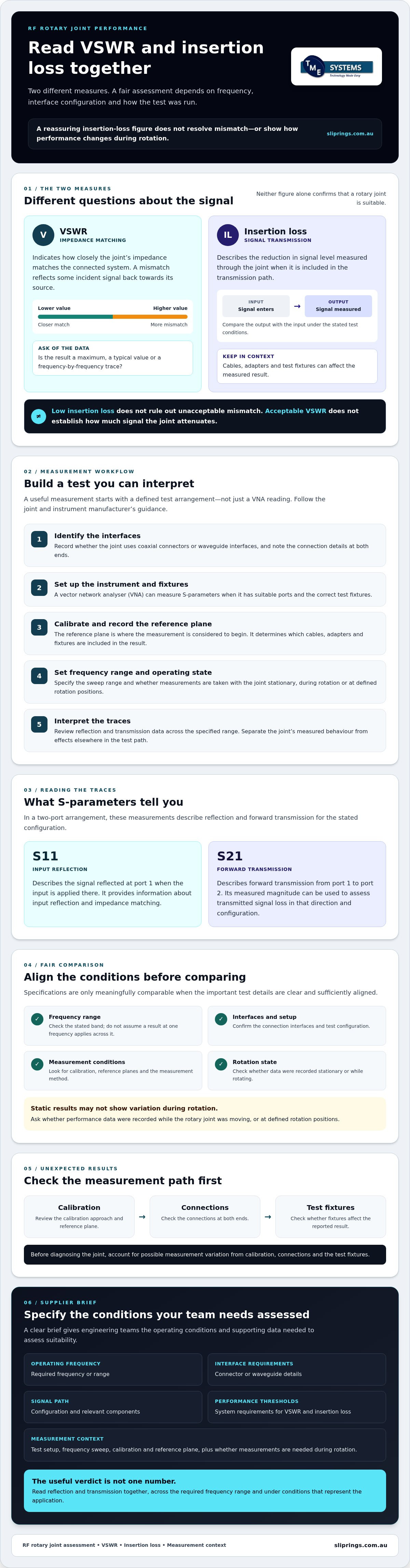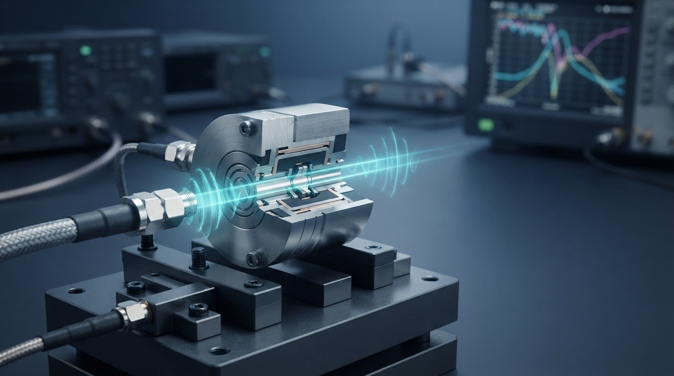
A low insertion-loss figure can look reassuring, but it does not resolve mismatch or performance changes during rotation. That is why VSWR and insertion loss in RF rotary joints need to be read together, not treated as a complete pass-or-fail verdict.
If a datasheet leaves out the frequency range, test configuration or measurement conditions, it is difficult to compare results fairly. A rotary interface can also behave differently during rotation than a static connector or cable test suggests. The figures matter, but so does the method used to obtain them.
This article explains what VSWR and insertion loss reveal, how to interpret test data in context, and what to confirm before selecting a component. Frequency, interface configuration and test methodology all affect a fair comparison. Performance data recorded during rotation can also expose variation that static results may not show. Use these points to prepare a supplier brief with the operating conditions and supporting data your engineering team needs to assess suitability.
Key Takeaways
- Read VSWR and insertion loss in RF rotary joints together to assess mismatch and signal attenuation, rather than relying on one figure alone.
- Check how measurements were taken, including the frequency range, test setup and whether results were recorded while the joint was rotating.
- Compare specifications only when the interfaces and measurement conditions are sufficiently aligned.
- Before diagnosing unexpected results, check calibration, connections and test fixtures for sources of measurement variation.
- Prepare a supplier brief with the operating frequency, interface requirements, signal path and system performance thresholds.
What do VSWR and insertion loss mean in an RF rotary joint?
VSWR: Indicates how closely the RF rotary joint’s impedance matches the connected system. An impedance mismatch reflects some of the incident signal back towards its source.
Insertion loss: Describes the reduction in signal level measured through the joint when it is included in the transmission path.
These measures describe different aspects of RF performance. VSWR concerns reflected energy at an interface, while insertion loss concerns the signal level at the output relative to the input. Neither figure alone confirms that a joint is suitable. Assess each across the required operating frequency range and alongside the stated measurement conditions.
How VSWR describes impedance matching
When the impedance of the rotary joint and the connected transmission system do not match, part of the incident signal is reflected. The incident and reflected waves combine to form a standing-wave pattern along the line. VSWR expresses this relationship: a lower value indicates a closer match, while a higher value indicates more mismatch. This overview explains Standing Wave Ratio (SWR).
A single VSWR figure is incomplete without its frequency context. Matching can vary across a device’s operating band, so check whether the result is a maximum, a typical value or a frequency-by-frequency trace. Confirm the test setup and connection interfaces as well. Do not assume a figure measured at one frequency applies across the full band.
How insertion loss describes transmitted signal loss
Insertion loss is the reduction in transmitted signal level when a component is placed in the signal path. It indicates how much less signal is measured at the output than at the input under the stated test conditions. For a rotary joint, this metric helps assess the signal passing through the rotating interface, but it does not describe impedance matching on its own.
Separate the joint’s contribution from losses in cables, adapters and test fixtures. These items can affect the measured result, particularly if the setup has not been properly accounted for. Ask where the measurement reference planes were set and whether the reported value represents the joint alone or the complete test path. Check that the result states the frequency or range and describes the measurement method.
Read VSWR and insertion loss in RF rotary joints together, then relate both results to the system’s requirements. A low insertion-loss figure may still coincide with an unacceptable mismatch, while an acceptable VSWR does not establish how much signal the joint attenuates. Compare data only when the frequency range, interfaces and test conditions are clear.
How are VSWR and insertion loss measured across an RF rotary joint?
A useful measurement starts with a defined test arrangement, not just a vector network analyser (VNA) reading. The joint’s connector or waveguide interface, operating frequency range and manufacturer’s test guidance determine the suitable setup. Do not assume one configuration applies to every rotary joint.
Measurement workflow
- Identify the interfaces. Record whether the joint uses coaxial connectors or waveguide interfaces, and note the connection details at both ends.
- Set up the instrument and fixtures. A VNA can measure S-parameters when it has suitable ports and the correct test fixtures. Follow the instrument and joint manufacturer’s instructions for connections and handling.
- Calibrate the measurement. Record the calibration approach and reference plane, the point at which the measurement is considered to begin. The reference plane determines which cables, adapters and fixtures are included in the result.
- Set the frequency range and operating state. Specify the sweep range and whether measurements are taken with the joint stationary, during rotation or at defined rotation positions. Use manufacturer guidance to determine the appropriate method.
- Interpret the traces. Review reflection and transmission data across the specified range. Separate the joint’s measured behaviour from effects that may come from connections or the rest of the test path.
What the S-parameters show
For a two-port arrangement, S11 describes the signal reflected at port 1 when the input is applied there. It provides information about input reflection and impedance matching. S21 describes forward transmission from port 1 to port 2. Its measured magnitude can be used to assess transmitted signal loss for that direction and configuration. This VSWR definition outlines the relationship between reflection and matching.
These labels depend on the defined port arrangement. If the VNA’s source is connected to port 1 and its receiver to port 2, S21 is the forward result from the source side to the receiver side. Reversing the connections changes the measurement direction. Record that direction rather than treating the label as independent of the setup.
Why test conditions change the result
Frequency range, interface type, cable arrangement, fixtures and calibration reference plane all shape what the VNA measures. Testing during rotation may also reveal variation that a stationary test does not capture. Ask whether a report covers rotation and whether it records continuous operation or particular positions. Mark any condition the manufacturer has not confirmed as requiring verification.
When test data or setup details are incomplete, include the operating frequency, interface type and required performance data in a technical application consulting enquiry. This helps clarify selection requirements without assuming that a particular rotary connector has confirmed RF performance.
How should engineers compare VSWR and insertion loss specifications?
Compare specifications only when they describe sufficiently similar tests. A headline figure can conceal differences in frequency coverage, interface, calibration or operating state. For a fair assessment of VSWR and insertion loss in RF rotary joints, review the conditions alongside the values and relate them to the system’s requirements.
| Metric | What it indicates | Required context | Selection questions |
|---|---|---|---|
| VSWR | Impedance matching and the degree of reflection at the measured port. | Frequency range, port or interface, test arrangement, and whether data is a sweep or a single point. | Does the result cover the full operating band? Are reflection or return-loss data available? |
| Insertion loss | Reduction in transmitted signal level through the measured path. | Frequency, measurement direction, reference plane, and whether the result covers the joint alone or the full test assembly. | Are cables and fixtures included? How does the result fit the system’s signal-loss budget? |
| Rotational variation | Change in measured performance as the joint turns, if assessed. | Whether the test was stationary, during rotation or at specified positions, plus the measurement method. | Does the data reflect the joint’s operating condition? |
Read VSWR alongside frequency and reflection data
Check whether the specification provides a frequency sweep or only a value at one frequency. Frequency-dependent data can reveal variation across the band that a single headline figure cannot. Where available, review the corresponding reflection or return-loss results and confirm that the test interface and conditions match your application. Do not assume a stated value is acceptable for every system. Set the required threshold from the system requirements or with the responsible engineer.
Read insertion loss alongside the complete signal path
Confirm whether the figure represents the joint by itself or a test assembly that includes cables, adapters or fixtures. Results from different setups may not be directly comparable, even if both are reported as insertion loss. Check that the frequency bands, connector or waveguide interfaces, measurement direction and reference planes align before drawing a conclusion.
A lower insertion-loss value does not, on its own, prove better system performance. The joint may still have a mismatch outside the required limit, or its test conditions may differ from the intended application. Assess insertion loss within the overall signal-loss budget, and evaluate VSWR against the system’s matching requirements. Compare the paired evidence, not an isolated number.
What can cause unexpected VSWR or insertion-loss results?
An unexpected reading does not automatically indicate a fault in the RF rotary joint. Calibration, connector seating, cable movement and test fixtures can all affect the result. Check the measurement chain first, then assess whether any remaining variation reflects the joint’s behaviour under the conditions tested.
Check the RF measurement setup first
Begin with the connections and fixtures. A connector that is not seated consistently, a cable routed differently between tests or a shifting fixture can change the measured result. Confirm that calibration is current for the setup, and check that the reference planes and test configuration match the documented procedure.
Repeat the measurement using the same equipment, connections, cable arrangement and settings. Consistent results make it easier to distinguish a repeatable change from setup variation. Record the method and readings so they can be reviewed alongside manufacturer data.
Check the operating state and application conditions
Record the frequency and whether the joint was stationary, rotating or tested at specified rotation positions. If readings change during rotation, assess them against the manufacturer’s stated test method. A stationary measurement and a rotating measurement describe different test conditions, so do not treat them as directly interchangeable.
Note relevant environmental or mechanical conditions that may affect the test. Compare field readings with manufacturer results only when the interfaces, frequency range and measurement arrangements are comparable. If details are unconfirmed, mark them for verification rather than filling gaps with assumptions.
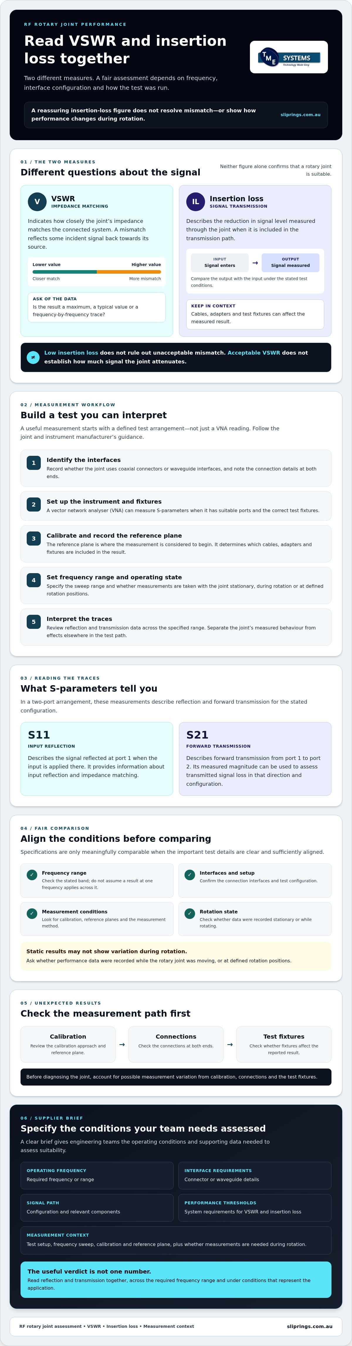
Measurement check before diagnosis:
- Confirm connector seating, cable routing and fixture positioning.
- Record instrument calibration, reference planes and test configuration.
- Repeat the measurement using the same documented setup.
- Log frequency, rotational state and relevant operating conditions.
- Check that manufacturer data uses a comparable method before interpreting differences.
Verify unexpected VSWR and insertion loss in RF rotary joints before attributing either result to the joint. If repeatable readings still differ from expected performance, provide the measurement setup, operating conditions and available test data for technical review. TME Systems offers technical application consulting to help assess rotary connector requirements. Confirm RF-specific capability and performance data with the manufacturer.
How do you specify an RF rotary joint for an application?
A useful supplier brief turns system needs into information that can be checked against manufacturer data. Set out the requirements first, then request evidence for the proposed component. This helps prevent a headline VSWR or insertion-loss value from being assessed without its frequency range, test conditions or relevance to the application.
Prepare the technical information for supplier review
Build the brief in sequence. Separate confirmed system requirements from details that still need engineering review.
- Define the RF operating range. State the required frequencies and whether the signal operates across a band or at defined frequencies.
- Specify the interfaces. Identify the connector or waveguide type at each end, along with any interface or mounting constraints that affect integration.
- Describe the signal path. Show how the joint connects to the surrounding equipment, including the direction of transmission and any relevant cables or components.
- Set system performance thresholds. Provide the required VSWR and insertion-loss limits, and identify which come from system design or the responsible engineer. Mark undecided limits clearly rather than treating them as established requirements.
- Record operating and test conditions. State whether the joint must perform while stationary, rotating or at defined positions, and include relevant environmental or mechanical conditions.
- Request supporting evidence. Ask for manufacturer-confirmed VSWR and insertion-loss data across the required frequency range, with the measurement configuration, interface details and test conditions stated. Request supporting traces or reports where available.
If a specification provides only a single figure, ask what frequency and test arrangement it represents. Clarify whether the measurement covers the joint alone or includes fixtures and connections. This gives the engineering team a sound basis for comparing the data with the system’s requirements.
When application engineering can help
Technical application consulting can help review rotary connector requirements and identify information missing from a selection brief. TME Systems provides this consulting for rotary connector selection. However, the RF capability and performance of any specific product must be confirmed with its manufacturer. Do not assume that a listed slip ring or rotary connector is an RF rotary joint.
Share the operating frequency, interface type, signal path, required performance thresholds and available test data when seeking a review. If you are also assessing broader rotary electrical connector requirements, keep procurement information distinct from RF performance evidence, and confirm that any reference material applies to the component and application under consideration.
Information about TME Systems’ technical application consulting is available online.
Make your next selection evidence-based
VSWR and insertion loss in RF rotary joints are useful selection measures when assessed together and in context. Confirm the operating frequency, interface and measurement conditions behind each result, and check whether the data represents stationary or rotating operation. A single headline figure cannot establish suitability.
Before supplier review, bring together the system’s performance thresholds, signal path and available test data. Ask the manufacturer to confirm the relevant specifications and test method, and identify any requirements that still need engineering input.
TME Systems supplies industrial slip rings and rotary electrical connectors, and offers technical application consulting to help match rotary connectors to application requirements. Share your operating frequency, interface type and required performance data to support a focused review.
With the right information in hand, you can compare options more confidently and move towards a component decision grounded in your application’s needs. Discuss your rotary connector application with TME Systems.
Frequently Asked Questions
What is VSWR in an RF rotary joint?
VSWR indicates how closely the impedance at the measured interface matches the connected RF system. If the impedances differ, some incident signal reflects towards its source. A lower VSWR indicates a closer match under the stated test conditions, but it is not a universal value for every frequency or operating state. Check the frequency range and test method before using a figure to assess an RF rotary joint.
What does insertion loss mean for an RF rotary joint?
Insertion loss is the reduction in transmitted signal level when the RF rotary joint is included in the signal path. It is commonly reported in decibels, but the value needs context: check the frequency, measurement direction and reference plane. Confirm whether the figure represents the joint alone or includes cables, adapters and test fixtures. This helps distinguish the component’s contribution from losses elsewhere in the measurement path.
Can VSWR and insertion loss be compared directly?
No. VSWR and insertion loss in RF rotary joints describe different performance measures: VSWR relates to impedance matching and reflected signal, while insertion loss describes reduced transmission through the path. Assess them together against the application’s requirements, rather than comparing the numbers directly. For a meaningful comparison between components, align the frequency range, interface, measurement arrangement and operating state, and check that each specification uses clearly stated test conditions.
How are VSWR and insertion loss measured?
A vector network analyser can measure S-parameters when suitable ports and test fixtures are available. In a defined two-port setup, S11 describes input reflection and S21 describes forward transmission from port 1 to port 2. The measurement needs appropriate calibration and a stated reference plane. Record the interface, frequency range and whether the joint is stationary or rotating. Follow manufacturer guidance, as the suitable method depends on the joint configuration.
Does a lower insertion loss always mean a better RF rotary joint?
No. A lower insertion-loss figure does not establish suitability by itself. The joint may still have a mismatch that falls outside the system’s requirements, or the result may have been measured under conditions that do not match the application. Review VSWR and insertion loss together, check the evidence across the required frequency range, and consider how the results fit the system’s performance thresholds and overall signal-loss budget.
Why might an RF rotary joint’s measured VSWR change?
VSWR readings can vary because of the joint’s operating state or the test setup. Rotation may produce changes that a stationary measurement will not reveal. Connector seating, cable routing, calibration, fixtures and reference-plane placement can also affect results. Repeat the measurement using the same documented configuration, and compare it with manufacturer data only when the frequency, interfaces and test conditions are comparable. Verify unexpected readings before attributing them to the joint.
What information should I provide when requesting an RF rotary joint?
Provide the operating frequency or band, connector or waveguide interfaces, signal path and required VSWR and insertion-loss thresholds. Include relevant operating conditions, whether the joint must be assessed while rotating, and any available test reports or measurement details. Mark which limits are confirmed by system design and which need review. TME Systems provides technical application consulting for rotary connector selection, but confirm RF capability and performance data with the manufacturer.