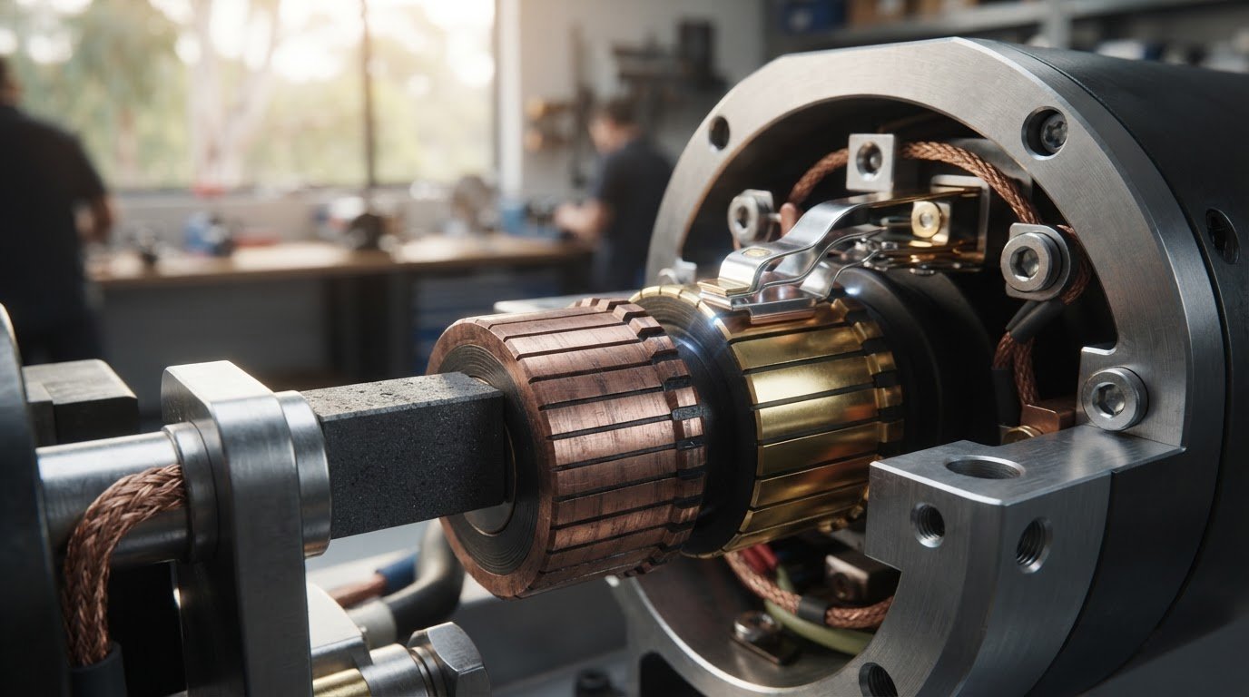
Lower friction does not automatically make one contact the better choice. Upgrading from carbon brushes to precious-metal contacts may suit a motor where low electrical noise and steady contact resistance matter. The right option still depends on the motor’s duty and operating conditions.
Both contact types transfer current between stationary and rotating parts, but they respond differently to load and motion. Whether upgrading from carbon brushes to precious-metal contacts suits your application depends on the operating profile, not material preference alone.
This article explains how carbon brushes work, compares their characteristics with precious-metal contacts, and outlines what to assess. Use it to decide whether upgrading from carbon brushes to precious-metal contacts suits your equipment.
Key Takeaways
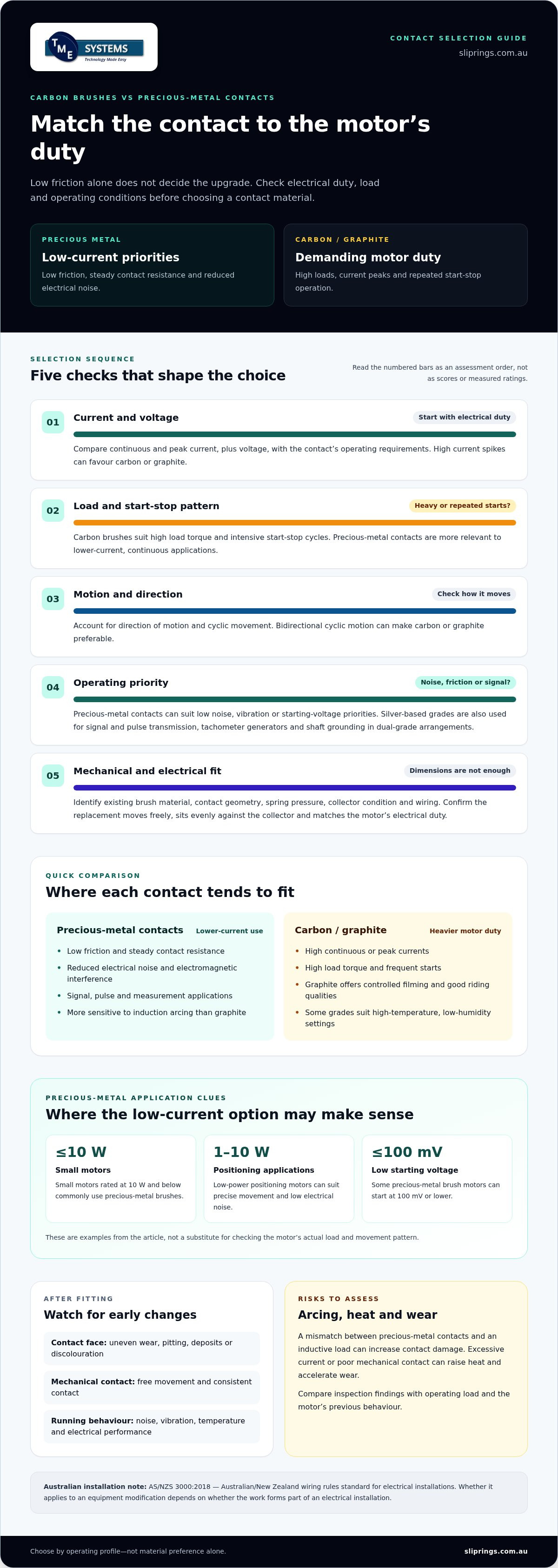
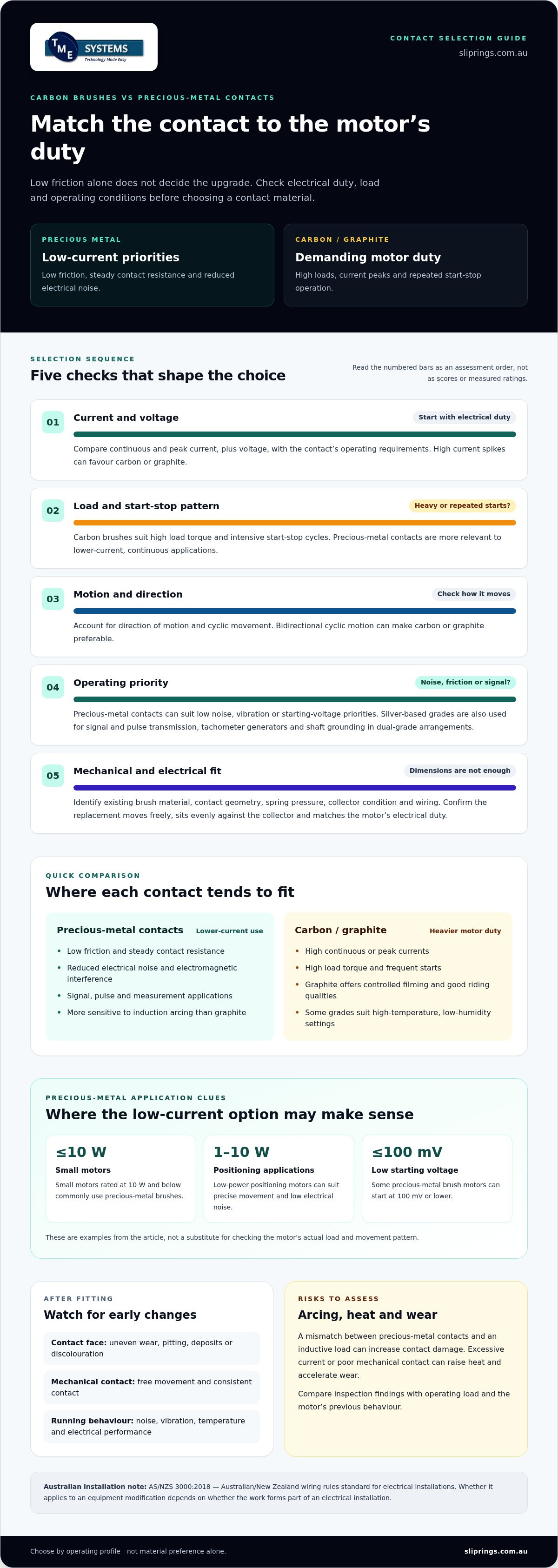
- Precious-metal contacts can suit applications where low friction, steady contact resistance and reduced electrical noise matter.
- Carbon brushes are often better suited to high loads, current peaks and frequent start-stop operation.
- Compare the motor’s current, voltage and load behaviour with the contact’s operating requirements before selecting a replacement.
- Application conditions, including motion, environment and mechanical compatibility, affect whether a contact change is appropriate.
- Consider arcing, heat and wear as part of the upgrade assessment, particularly where precious-metal contacts face inductive loads.
How Do I Choose Between Precious Metal and Carbon Brushes?
Choose by matching contact material to current, load, motion and operating priorities. Precious-metal contacts favour low friction and electrical noise, while carbon brushes handle demanding loads and repeated starts.
Brush Material Characteristics and Benefits
Brush material affects contact resistance, friction, current capacity and performance on the collector. Precious-metal alloys, including silver, gold and platinum, offer low contact resistance. Precious-metal brushes also provide low friction and steady contact resistance, supporting efficiency and reduced electromagnetic interference.
Carbon brushes suit high continuous or peak currents, high load torque and intensive start-stop cycles. Graphite brushes offer controlled filming and good riding qualities on commutators and slip rings. Electrographitic grades support commutation in high-temperature, low-humidity settings, while carbon graphite grades generally suit lower current densities on older, slower-speed machines.
Suitable Applications and Electrical Ratings
Precious-metal brushes are commonly suited to lower-current, continuous applications where low noise, vibration or starting voltage matters. Small motors rated at 10 W and below commonly use them; some can start at 100 mV or lower. Silver-based grades also suit signal and pulse transmission, tachometer generators and shaft grounding in dual-grade arrangements.
Before selecting a contact, compare the motor’s continuous and peak current, voltage, load torque, start-stop frequency and direction of motion. Carbon or graphite may be preferable where high current spikes or bidirectional cyclic motion dominate. Precious-metal contacts are not automatically suitable simply because low friction is desirable.
Installation and Equipment Compatibility
Compatibility means the contact matches the motor’s collector, mechanical arrangement and electrical duty. Before fitting a replacement, identify the existing brush material, contact geometry, spring pressure, collector condition and wiring. Then compare the proposed contact’s current and voltage requirements with the motor’s operating conditions.
Fit contacts evenly against the collector and confirm they move freely through the holder. Check that connections are secure and the contact surface meets the collector correctly. A motor designed around graphite’s current capacity may not suit precious metal just because the dimensions appear compatible.
For Australian electrical installations, AS/NZS 3000:2018 is the Australian/New Zealand wiring rules standard for electrical installations. Whether it applies to a particular equipment modification depends on whether the work forms part of an electrical installation.
Upgrade Risks and Contact Care
Precious-metal brushes are more sensitive to induction arcing than graphite brushes. A mismatch between contact material and inductive load can increase contact damage. Excessive current or poor mechanical contact can also raise heat and accelerate wear. Oxidation resistance supports precious-metal brushes’ long shelf life.
After installation, inspect the contact face and collector for uneven wear, pitting, deposits or discolouration. Check that the brush moves freely and maintains contact during operation. Record changes in noise, vibration, temperature and electrical performance against the motor’s previous behaviour.
After fitting precious-metal contacts, inspect the contact surfaces, collector condition and holder movement. Tie inspection findings to operating load and observed wear so you can distinguish emerging changes from normal running marks.
Which applications benefit from replacing carbon brushes with precious metal contacts?
Precious-metal contacts are most relevant when an application prioritises low-current continuity, quiet operation or clean surroundings. Suitability depends on what the motor does during operation, not simply on whether another brush material is available. A positioning motor, for example, has different demands from a drive facing repeated heavy starts.
Low-power positioning and quiet operation
Small DC motors used for positioning can benefit from precious-metal brushes when precise movement and low electrical noise matter. Low friction can support efficiency and battery life, while low brush pressure supports low no-load current and low starting voltage. Precious-metal brush motors are typically used at 10 W and below, and low-power positioning applications can have output power of 1-10 W.
These characteristics can suit equipment that moves a mechanism into position, then runs continuously at relatively low current. Low audible noise and vibration can also make precious-metal contacts worth considering when motor sound affects equipment operation. Compare the motor’s actual load and movement pattern with the contact’s intended duty.
Signal transmission and measurement
Silver-based brush grades are used for signal-current and pulse transmission to rotating devices. This makes them relevant to rotating measurement assemblies, including tachometer generators, where electrical continuity carries a signal rather than driving a high-load mechanism. Their use in aerospace and space applications also reflects the need to match contact material to a specific electrical function.
In shaft-grounding applications, silver-based grades can be used in a dual-grade construction. This differs from replacing a motor brush solely to reduce noise: the contact arrangement serves a defined electrical purpose. Identify whether the circuit carries a signal, pulse or grounding current before deciding whether precious metal is appropriate.
Clean environments and optical equipment
Graphite brushes produce graphite dust, making them unsuitable for optical systems where particles can interfere with sensitive components. A precious-metal contact may be worth assessing when brush dust is incompatible with the surrounding equipment. Consider the complete assembly, including where particles could travel and which parts need protection.
Low noise and reduced vibration can also matter in precision equipment. However, an optical or quiet-running application still needs contacts matched to its electrical load and operating pattern. Replacing graphite addresses dust from the brush material, but does not by itself resolve other contamination or compatibility concerns.
When replacement may not suit
Carbon brushes remain appropriate for demanding loads and intensive start-stop operation. Precious-metal contacts are typically associated with continuous operation at lower current loads, particularly where graphite’s durability is not required. A high-load pump or a drive with substantial current peaks may therefore favour carbon rather than a material change.
For designs transferring current across a rotating assembly, consider whether a separate rotary connection suits the arrangement better than changing motor brushes. Mercotac slip rings are one rotary-connection option to assess for that distinct application.
What electrical current, voltage, and load ratings should be checked before upgrading?
Compare the contact’s electrical duty with the motor’s full operating profile, not just its nameplate voltage. Current peaks, starting behaviour and mechanical load can make a precious-metal contact unsuitable even when steady running appears modest. For a brushed DC motor, record supply voltage, current under load and the most demanding operating condition before assessing a replacement.
Start with current. Separate continuous or RMS current from short-duration peak current, then identify when each occurs. Acceleration, reversing and start-stop cycles can produce spikes that differ from steady operation. Carbon brushes have high RMS and peak current capability, supporting high load torque and intensive starts. Graphite brushes can also withstand current spikes during bidirectional cyclical motion.
Next, check voltage at the motor terminals during starting and running. A brushed DC motor can operate from a DC supply varying between −12 V and +12 V, with speed and direction responding to voltage and polarity. That example illustrates why a single supply label may not describe the full duty. Record the actual voltage range and polarity changes, then compare them with the contact and motor specifications.
Assess load alongside electrical readings. A pump that starts against resistance, for example, places different demands on its contacts from a lightly loaded positioning mechanism. Note load torque, acceleration, direction changes and how often the motor stops and starts. High load torque and frequent starts favour carbon or graphite characteristics; low-current, continuous duty may place greater emphasis on contact resistance and friction.
- Continuous current: record the sustained current during normal loaded operation.
- Peak current: capture acceleration, reversal and start-up events.
- Voltage behaviour: document running, starting and polarity conditions.
- Mechanical duty: describe torque, cycling and direction changes.
Keep readings tied to specific operating modes. A motor that runs unloaded during commissioning may draw more current once connected to its pump, valve or driven assembly. Compare loaded and unloaded operation, and include the most demanding normal cycle rather than relying on an average that conceals short peaks.
Then compare those measurements with the contact’s stated current and voltage limits, including the conditions attached to each rating. Don’t assume a material change preserves the original margin: precious-metal contacts have different electrical behaviour from carbon brushes. Consider actual current peaks, voltage variation and load together, because no single rating describes the application on its own.
Finally, consider whether the intended duty is continuous or highly dynamic. Precious-metal brushes are typically associated with lower-current continuous operation, while high current peaks and high-load torque point towards carbon or graphite. If the motor reverses under load, include that condition in your assessment; the current profile during bidirectional motion can determine whether the proposed contact is suitable.
What are the installation steps and compatibility requirements for a contact upgrade
A successful brush change depends on matching the replacement to the motor’s electrical duty and physical assembly. Use equipment drawings, the existing brush arrangement and operating records to assess compatibility before fitting precious-metal contacts. A change in contact material can affect how the motor starts and runs, even when the replacement appears to fit.
- Document the existing arrangement. Record the brush shape, dimensions, holder position, lead connection and spring arrangement. Photograph the carbon brush and commutator before removal. These details help identify whether the proposed contact is a direct mechanical fit or changes pressure, alignment or the electrical path.
- Inspect the collector and holder. Look for uneven wear, grooves, deposits, looseness or restricted brush movement. A new contact cannot correct a damaged commutator or a binding holder. For example, a brush that catches in its holder may lose consistent contact, despite having suitable electrical properties.
- Compare electrical and mechanical compatibility. Match the replacement’s current and voltage ratings to the motor’s operating conditions. Check contact dimensions, lead connections, holder clearance and movement against the collector. A contact that fits the holder but meets the collector at an angle can wear unevenly.
- Fit the replacement to the designed contact path. Follow the motor manufacturer’s installation information for the brush holder and collector. Keep leads clear of moving parts, and ensure the contact can travel freely as it wears. Don’t alter holder pressure or collector geometry to force a different contact into place.
- Test under operating conditions. Use the equipment’s normal test procedure, then observe the motor under representative load and motion. Check starting behaviour, current draw, noise, vibration and contact tracking. A motor running smoothly without load may behave differently when its driven mechanism is engaged.
Mechanical fit alone does not establish suitability. Precious-metal contacts differ from carbon brushes in friction and electrical behaviour, so a replacement can affect starting and running. Continuous low-current service also differs from repeated acceleration or bidirectional movement. Record the installed contact and compare motor behaviour under similar test conditions.
For Australian electrical installations, the relevant wording is: AS/NZS 3000:2018 - Australian/New Zealand wiring rules standard for electrical installations. Whether the standard applies depends on whether the work forms part of an electrical installation.
Keep the motor’s original specifications and replacement details together. Record the contact material, holder arrangement and test observations. For example, compare starting performance and running current before and after the change under similar load conditions. This record can help distinguish contact wear from collector condition or a change in operating demand.
If the motor forms part of a larger assembly, assess how its wiring, driven load and control system interact with the replacement. Treat a brush-material change as part of the equipment design if it affects electrical continuity or motor response. Use the manufacturer’s fitting information and relevant installation procedures throughout the work.
What are the risks of arcing, overheating, oxidation, or accelerated wear after upgrading
Changing contact material changes how the brush and collector behave under electrical load. Precious-metal brushes are more sensitive to induction arcing than graphite brushes, so assess the motor’s inductive duty before and after a change. A contact suited to steady operation may respond differently during acceleration, reversal or repeated switching.
Arcing can pit a contact surface and interrupt consistent electrical transfer. If a motor drives an inductive load, observe it during start-up, stopping and direction changes, rather than assessing unloaded running alone. Carbon or graphite may be more suitable where current spikes and bidirectional cycles place greater demands on contact stability.
Overheating can result from excessive current, poor contact or restricted ventilation. Heat may increase wear at the brush and collector, while a loose connection can add resistance at the terminal. During a test under representative load, compare temperature, current and operating behaviour with the motor’s normal baseline. Check ventilation and loading if brush performance changes.
Oxidation needs a different interpretation. Precious-metal brushes resist oxidation, supporting long shelf life, but that property does not remove the need to inspect the contact interface. Look for surface deposits, discolouration or uneven contact marks. A clean-looking brush alone does not establish consistent electrical contact throughout rotation.
Accelerated wear can point to a mechanical problem rather than the material alone. Check vibration, brush movement, collector condition, air contamination and motor ventilation. For example, a brush that binds in its holder can lose consistent contact, while vibration can disturb the contact path. Graphite dust may matter in optical or contamination-sensitive equipment.
Use a repeatable inspection sequence after installation:
- Observe the running motor: note visible arcing, unusual noise and vibration during representative operation.
- Inspect contact surfaces: look for pitting, deposits, uneven wear and discolouration on the brush and collector.
- Review operating conditions: compare load, current behaviour, ventilation and contamination with earlier observations.
- Record changes: note where wear appears and whether it coincides with starting, reversal or continuous running.
Tie observations to operating conditions. A mark appearing after repeated reversals may have a different cause from wear during steady rotation. Likewise, a temperature rise under load calls for checking current demand and ventilation, not simply replacing the brush again.
Use the findings to judge whether the new contact suits the application. Persistent arcing, rising heat or uneven wear signals a need to reassess contact material, electrical duty and mechanical fit. A material change cannot compensate for a damaged collector, restricted holder or unsuitable load profile.
TME Systems: Mercotac Slip Rings
TME Systems Pty Ltd can help assess whether a slip ring suits an application requiring electrical continuity between stationary and rotating parts. Its range includes Mercotac Slip Rings, Meridian Laboratory Slip Rings, BGB Innovation Slip Rings and Prosper Rotation Slip Rings.
A slip ring provides a rotary electrical connection, rather than a direct brush replacement for every motor. It may suit equipment that transfers power or signals across a rotating interface. Selection depends on circuit count, current, voltage, rotational speed, mounting style and operating environment.
For an application discussion, prepare the electrical ratings, movement profile and mounting constraints. Contact TME Systems Pty Ltd to discuss your requirements.
Set the Next Design Decision
Before upgrading from carbon brushes to precious-metal contacts, define what the rotating interface must do. A motor brush and a rotary electrical connection address different design requirements, so identify whether the change concerns the motor’s commutator or the transfer of power and signals across a rotating assembly.
That distinction gives your next engineering discussion a clear starting point. Note the equipment function, how the assembly moves and which electrical paths need to cross the rotation point. With that context, you can focus on a contact solution that fits the system rather than treating material choice as an isolated component decision.
TME Systems Pty Ltd supplies Mercotac Slip Rings, Meridian Laboratory Slip Rings and BGB Innovation Slip Rings for rotary electrical connection requirements. Each project’s operating conditions and mechanical arrangement inform the selection.
For a discussion about your application, contact TME Systems Pty Ltd. A clearly defined requirement is a practical first step towards a suitable design.
Frequently Asked Questions
What are precious metal contacts in electrical switching devices?
Precious-metal contacts use conductive metals or alloys, such as silver, gold or platinum, at the electrical interface. In a switching device, the contact surfaces meet to establish a circuit and separate to interrupt it. In a rotating assembly, a brush contact can maintain an electrical path against a collector as parts move. The contact’s role and geometry depend on whether the device switches a circuit or transfers current during rotation.
How do precious metal contacts compare with carbon brushes for conductivity, wear, and lifespan?
Precious-metal brush alloys can provide lower contact resistance and lower electrical noise than carbon brushes. Carbon brushes, however, have high continuous and peak current capability, which can suit high-load or frequent-start operation. Neither material has a universal service-life advantage: wear depends on current, contact pressure, surface condition and operating cycles. For example, quiet, low-current duty and a heavily loaded reversing motor place different demands on their contacts.
Can carbon brushes be directly replaced with precious metal contacts in an existing motor or switch?
Not as a drop-in change by assumption. A replacement must suit the device’s contact geometry, holder or mounting arrangement, electrical duty and switching behaviour. In a motor, the brush must track its commutator correctly; in a switch, the contact must fit the mechanism and its circuit duty. A physically similar part can still differ in pressure, resistance or current capability, so assess the complete interface before substitution.
What materials and contact designs are used for precious metal contacts?
Precious-metal contacts can use silver, gold or platinum alloys. Heraeus lists AgCu, AgNi, AuAgCu and PdAgCu as collector materials. Contact design is selected to suit the device’s interface: a brush must maintain contact with a collector, while a switch contact must meet its mating surface as the mechanism operates. Consider the alloy and geometry together, rather than selecting a material without regard to the contact arrangement.