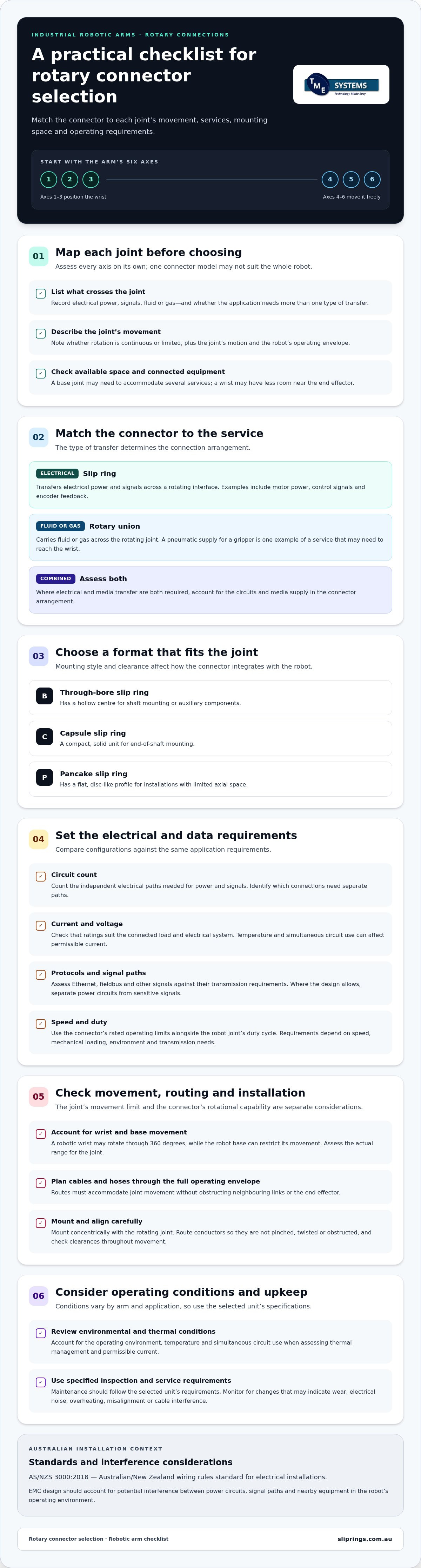
A rotary connector for industrial robotic arms must suit what passes through the rotating joint. A slip ring transfers electrical power and signals, while a rotary union carries fluid or gas. Some applications need both. A vertically articulated industrial robot generally has six joints, or axes, and each can have different movement and transfer requirements.
It’s easy to focus only on the joint’s rotation angle. The practical choice also depends on whether rotation is continuous or limited, the circuits or media involved, available mounting space and the robot’s motion. A connector suited to one axis may not suit another.
This guide explains how rotary unions and slip rings support robotic arm movement, what to consider when assessing wrist and joint rotation limits, and how rotary electrical joint options differ. It also covers the specifications that help narrow the choice, including circuit count, current, voltage, speed and mounting style, so you can compare configurations for your application.
Key Takeaways
- Map each robotic axis by the electrical power, signals or fluid it must carry before selecting a rotary connection.
- Separate the joint’s movement limit from the connector’s rotational capability; wrist motion and cable routing can affect the design.
- Compare slip ring models by circuit count, current, voltage, speed and mounting style rather than by axis position alone.
- For combined electrical and fluid transfer, assess whether the application needs a slip ring, a rotary union or both.
- TME Systems’ slip ring range and technical application consulting can help align connector selection with the arm’s operating requirements.
Rotary axis product models for industrial robotic arms
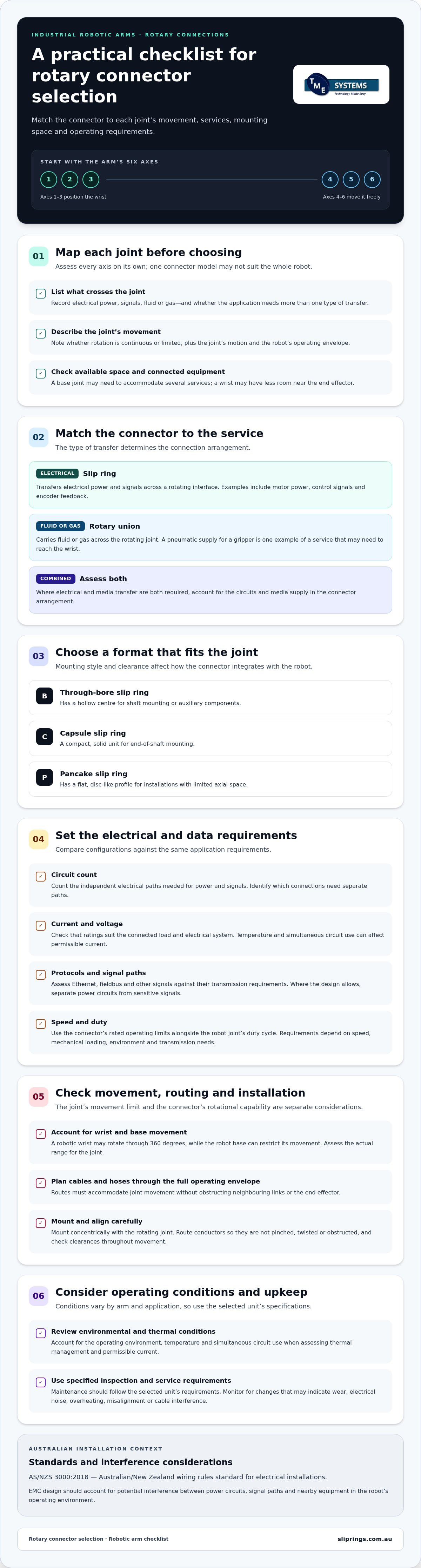
A vertically articulated industrial robot generally has six joints, or axes. Its first three axes position the wrist, while the next three move it freely. Each axis can perform a different function and carry different services. Selecting a rotary connector for industrial robotic arms means matching it to each axis’s movement and transfer requirements, rather than choosing one model for the whole robot.
A slip ring transfers electrical power and signals across a rotating interface. A rotary union carries fluid or gas. Some applications need both, so the connector arrangement must account for electrical circuits and media supply. Start by identifying what crosses each joint, then consider its movement, available space and connected equipment.
For a six-axis arm, assess each joint separately. The base axis may need to accommodate several services as the robot turns, while a wrist joint may have less mounting space near the end effector. For example, a welding tool may need electrical power and control signals. A gripper may also need a pneumatic supply, changing the services routed to the wrist.
Connector models differ in configuration and mounting format. A through-bore slip ring has a hollow centre for shaft mounting or auxiliary components. A capsule slip ring is a compact, solid unit for end-of-shaft mounting. A rotary union transfers media, while combined arrangements can accommodate electrical and media connections. Each format has different integration requirements within the robot structure.
Comparisons are useful when models are assessed against the same application requirements. Consider circuit count, current, voltage, rotational speed, mounting style and environmental conditions. More circuits or a different mounting arrangement can change the required configuration. A basic connector and an assembly carrying multiple services perform different functions, even if both suit robotic applications.
Media supply across six-axis movement requires careful routing of hoses and cables through the robot’s operating envelope. Routes must accommodate joint movement without obstructing neighbouring links or the end effector. Connector selection therefore involves assessing the route as well as the connector. Media, electrical paths, mounting space and axis movement all inform the choice.
For Australian electrical installations, AS/NZS 3000:2018 is the Australian/New Zealand wiring rules standard for electrical installations. EMC design should account for potential interference between power circuits, signal paths and nearby equipment in the robot’s operating environment.
Rotary unions and slip rings for automation
Across robot joints, a slip ring transfers electrical power and signals, while a rotary union carries fluid or gas. Some automation applications need both, so the connector arrangement must suit the joint’s movement and the services passing through it.
Data and signal transmission selection
When selecting a rotary connector for data, Ethernet, fieldbus or signal transmission, match its transmission capability to each protocol and circuit. Signal paths can be affected by electrical noise, circuit layout and the rotating interface. Where the design allows, separate power circuits from sensitive signals. An encoder feedback path and an Ethernet link, for example, have different transmission requirements, so assess each against its own operating specification.
Slip ring formats for robotic arms
A through-bore slip ring has a hollow centre for shaft mounting or auxiliary components, while a capsule unit is a compact, solid form for end-of-shaft mounting. A pancake slip ring has a flat, disc-like profile for installations with limited axial space. The choice matters at robot joints with different clearances: a through-bore can suit a shaft passing through the assembly, while a pancake can fit a shallow mounting envelope.
Circuit and electrical ratings
Circuit count is the number of independent electrical paths available for power and signal transmission. Set it by listing each required connection, such as motor power, control signals and encoder feedback, and identifying which need separate paths. Current and voltage ratings must suit the connected load and electrical system. Account for actual operating conditions, since temperature and simultaneous circuit use affect thermal management and permissible current.
Rotary connector installation and maintenance
Installation involves mounting the connector concentrically with the rotating joint and routing conductors so they are not pinched, twisted or obstructed. Poor alignment or cable routing can add mechanical stress and interrupt transmission. Follow the connector’s mounting arrangement and electrical connection requirements, then assess rotation, clearances and cable paths throughout the robot’s operating envelope. Maintenance should follow the selected unit’s specified inspection and service requirements.
For speed, torque, service life and maintenance, use the connector’s rated operating limits alongside the robot joint’s duty cycle. Required values depend on operating speed, mechanical loading, environment and transmission needs; no single set applies to every arm.
Potential risks include wear, electrical noise, overheating, misalignment and cable interference. Match the connector to its operating conditions, keep routes clear throughout the joint’s movement, and monitor performance for changes that may indicate developing faults.
Rotary wrist motion and rotation limits
A robotic wrist may rotate through 360 degrees, but the robot base can restrict its movement. The wrist’s range therefore cannot be assessed in isolation. Map the wrist and base movements together, then consider how motors, cables and connected services travel through the joint. For example, a tool that turns repeatedly in one direction places different demands on routing than a wrist that reverses within a fixed arc.
Joint limits vary by design and function. A robotic arm joint may move from 0 to 180 degrees, while another joint may have a full 360-degree range. These figures describe possible movement, not a specification that applies to every robot. Use the manufacturer’s axis limits and the programmed motion profile to determine the working range for each joint.
Servo motors typically have a rotational limit between 90 and 180 degrees. That motor limit is not automatically the same as the robot joint’s range, because transmissions and control systems also shape movement. Reduction gears, for example, can change output speed and torque. For a joint driven through gearing, assess the motion at the output shaft where the connector is mounted.
Mechanical interference can restrict rotation before the motor reaches its own limit. Collision with another robot component is one reason to limit a rotary joint’s angular range. Check the complete swept path, including the wrist, forearm, tool and nearby equipment. A welding torch or gripper may clear the workpiece in one orientation but collide with an adjacent link during another movement.
Compare commanded motion with the physical envelope. Review the smallest and largest joint angles, direction changes, pauses and repeated turns in the robot’s process. A pick-and-place cycle may reverse the wrist between positions, while a finishing process may require sustained changes in orientation. These examples help distinguish bounded rotation from a need for unrestricted turning.
Connector selection should follow the motion. The connector must accommodate the joint’s actual rotation and operating conditions, while its conductors and any media paths remain compatible with the robot’s movement. If the wrist is mechanically limited, select for that defined range rather than assuming continuous rotation. If the application allows repeated full turns, assess how the assembly handles that movement without restricting the robot.
For a practical review, document each axis limit, the base’s influence on wrist travel and any collision points. Then compare that envelope with the connector’s rotational capability and mounting arrangement. This links the robot’s programmed processes to its physical motion and helps prevent a mismatch between joint movement and rotary connection requirements.
Industrial robotic arms
An articulated industrial robot uses three or more rotary joints to position its tool through a work area. The joints form a serial chain, with each link’s movement affecting the next link’s position and orientation. This structure supports picking, placing, welding and assembly. The architecture helps determine where a rotary connector for industrial robotic arms must fit and which services need to move with the links.
A delta robot offers a contrast: its links form a parallel structure rather than a serial chain. This changes how movement and loads are arranged, affecting where a rotary connection can be integrated. A connector mounted at a joint must suit that joint’s function and available space, not just the robot’s overall task.
Industrial robot actuators can be powered electrically, hydraulically or pneumatically. An electric actuator may need electrical power and control signals, while hydraulic or pneumatic equipment also needs a fluid or air supply. Requirements depend on the robot and its end effector. Mapping them across the arm shows which joints need electrical transfer, media transfer or both.
End effectors attach to the wrist and can be changed for different tasks. Examples include grippers, vacuum tools, welding tools and painting tools. Changing the tool can alter the services required at the wrist. Selecting a rotary connector for industrial robotic arms therefore means considering the fitted end effector and its connections, not only the wrist’s mechanical movement.
Robot manufacturers may route cables and harnesses inside the arm to reduce interference with nearby equipment and support work in confined spaces. Motors may also sit away from joints, with belts or gears transmitting movement. These layouts affect available routes for wiring and auxiliary services, so connector integration depends on the robot’s mechanical arrangement.
- Picking and placing: a gripper or vacuum end-effector handles components as the arm moves between positions.
- Welding: a welding tool is mounted at the wrist, with service connections routed alongside the arm.
- Painting: a specialised tool is attached at the wrist for the process.
- Assembly: the arm positions components, where controlled movement supports precision.
For each application, match the connector to the robot’s links, actuator type and tool. A serial-link arm and a delta robot have different layouts, while internal harnesses and remote motors affect routing. These design details help establish how a rotary connection can transfer the required services without obstructing the arm’s movement or precision.
Joint geometry also sets a physical limit for connector movement. The described robot arm has a maximum angle of 160 degrees between the elbow and forearm joint and the connection with the base. Industrial robotic arms use rotary joints for tasks such as picking, placing, welding and assembling components. Motors can be placed away from joints, with belts and gears transmitting movement; this arrangement should be considered when tracing service routes around the arm.
How many electrical circuits and what current and voltage ratings are needed for a robotic arm rotary connector?
There is no fixed circuit count or electrical rating for every robotic arm. The right specification depends on the connected equipment, required signals and operating conditions. Build an inventory for each rotating interface, then match the connector’s independent paths and electrical ratings to that schedule.
Circuit count is the number of separate electrical paths available for power and signal transmission. List each connection that must cross the joint, such as motor supply, encoder feedback, control signals and tool connections. Keep distinct signals on separate paths where their functions require it. An encoder, for example, provides motor position information, while a motor circuit supplies power.
Current ratings should reflect the load on each power circuit during the robot’s operating cycle. Record the connected equipment’s electrical requirements and distinguish continuous operation from intermittent demand. Consider which circuits may operate simultaneously. A gripper and a welding tool have different electrical functions, so the fitted end effector affects the circuit schedule and load assessment.
Voltage ratings must suit the connected system and the installation’s insulation requirements. Where appropriate, separate power and low-level signal paths in the design, and assess the connector as part of the complete electrical assembly. Ambient temperature and heat from adjacent equipment also matter: thermal management affects allowable current, and thermal derating reduces permitted current as temperature rises.
For example, an arm carrying a motor, encoder and tool connection needs each function identified separately. The motor requires a power path; the encoder needs a path suited to its feedback signal; and the tool connection depends on the fitted equipment. This example does not establish a universal circuit count. It shows why the schedule must reflect the actual arm and tool configuration.
- Identify: record every power, control, feedback and tool connection crossing the rotating joint.
- Separate: distinguish independent circuits and signal types, including encoder feedback.
- Rate: capture each circuit’s current and voltage requirements, operating pattern and temperature conditions.
- Compare: match the schedule against the rotary connector’s ratings and arrangement.
Use the completed schedule to compare connector configurations, not just circuit totals. A unit may have enough paths but still be unsuitable if its electrical ratings or signal capability do not match the application. Include the robot’s operating conditions and connected tool in the final specification.
For help translating a circuit schedule into a suitable configuration, review rotary slip ring configurations alongside the arm’s electrical requirements.
TME Systems: Mercotac Slip Rings
TME Systems can help match a slip ring option to a robotic arm’s electrical requirements and mounting constraints. Start with the joint’s circuit count, current, voltage, speed and installation conditions. These details provide a practical basis for comparing available options.
Mercotac Slip Rings are one option, alongside Meridian Laboratory Slip Rings, BGB Innovation Slip Rings and Prosper Rotation Slip Rings. Compare them against the application’s power and signal paths, movement and physical arrangement, rather than the robot’s axis count alone. A clear specification helps focus selection on compatible configurations.
If you’re assessing a rotary connection for an industrial robot, contact TME Systems to discuss your application, or visit sliprings.com.au.
Turn your robot requirements into a connector specification
The next step is to turn the robot’s operating requirements into a specification for design review and procurement. A rotary connector for industrial robotic arms must fit its role within the complete assembly, not just the joint in isolation. A concise application brief can capture the robot configuration, connected equipment, operating environment and integration constraints for technical discussion.
TME Systems offers Mercotac Slip Rings, Meridian Laboratory Slip Rings and BGB Innovation Slip Rings, with technical application consulting to help assess options against your requirements. This can help when the design team is comparing connector approaches or translating the robot’s requirements into a suitable slip ring configuration.
Bring your application details to the discussion, including the joint’s function and the connections it must carry. Contact TME Systems about rotary connectors and take the next step towards a specification that suits your robot design.
Frequently Asked Questions
What is a rotary connector or slip ring in an industrial robotic arm?
In a robot, a rotary connector keeps selected electrical paths connected as one assembly turns relative to another. For example, a sensor on a moving wrist can remain linked to control equipment on a fixed structure. To define the requirement, identify which connections must remain active during movement and what the connected equipment needs from each path. This gives the design team a practical basis for specifying the interface.
Which rotary connector types are suitable for industrial robot joints?
Suitable options include brush-less, mercury-wetted connectors and industrial slip-ring assemblies, with the choice determined by the application. Mercotac® connectors are compact and provide low resistance and low noise. Meridian Laboratory (ROTOCON) connectors support high-current and high-speed applications, while BGB Innovation assemblies cover power, signal and data uses. These distinctions help narrow options by transfer requirements and operating conditions.
What do rotary connectors for industrial robots cost in Australia?
For an Australian robot project, identify the required model and configuration before comparing options. TME Systems supplies Mercotac, Meridian Laboratory, BGB Innovation and Prosper Rotation slip rings, with technical assistance for selection. Prepare the robot’s application requirements and installation constraints so the discussion can focus on relevant configurations. The robot category alone does not determine which product arrangement suits the application.
What Australian electrical safety and EMC standards apply to rotary connectors in industrial robots?
For Australian electrical installations, AS/NZS 3000:2018 is the wiring rules standard. EMC design should account for potential interference between power circuits, signal paths and nearby equipment.
What are the required speed, torque, service life, and maintenance specifications for robot slip rings?
Use the slip ring’s rated operating limits for speed, torque and service life alongside the robot joint’s duty cycle. Required values depend on operating speed, mechanical loading, environment and transmission needs. Follow the selected unit’s specified inspection and service requirements.