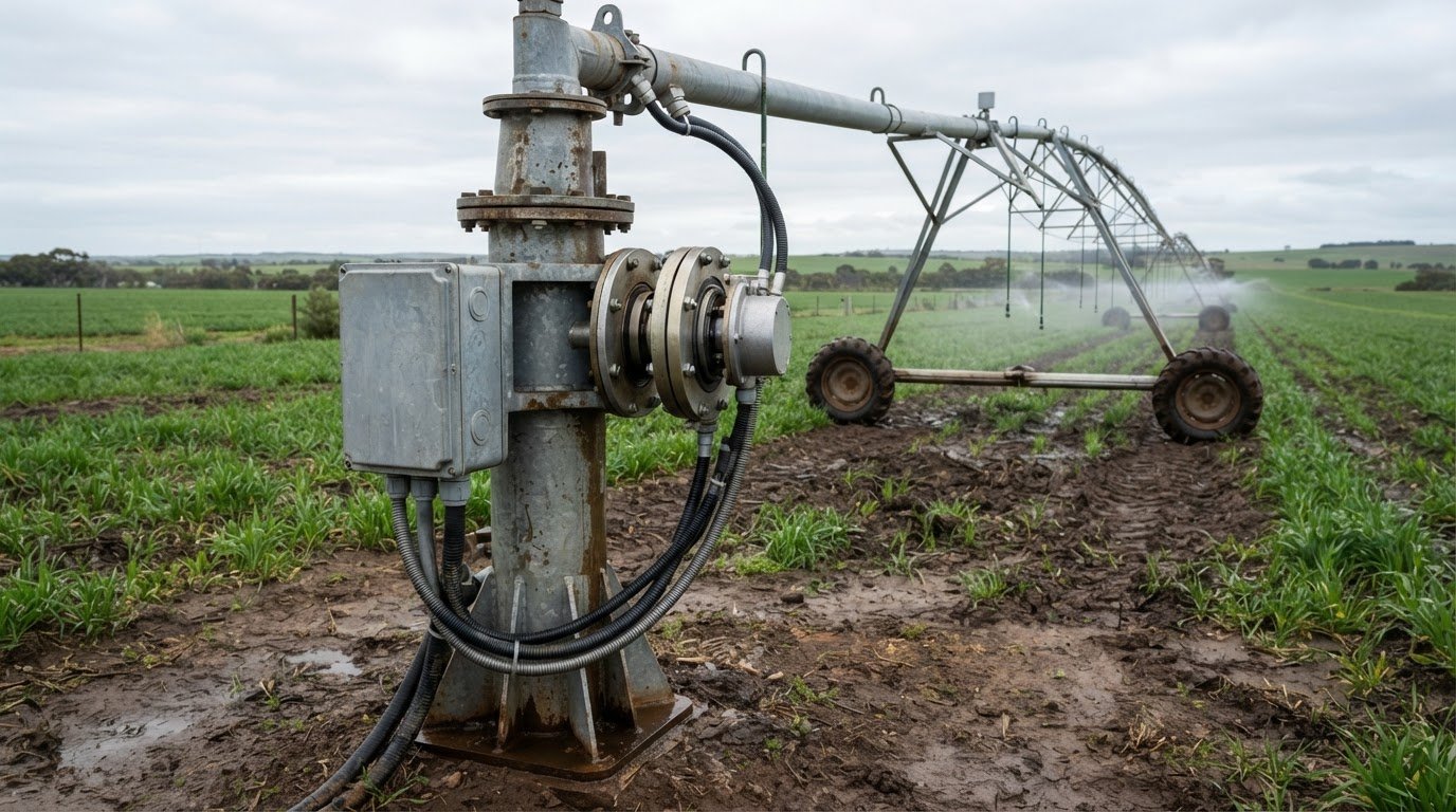
The right power connector for centre pivot irrigators must maintain electrical continuity while accommodating the system’s rotating structure. Electric motors drive pivot towers and water-delivery pumps, so connector selection must account for electrical load and the conditions around the equipment.
Choosing a connector involves more than matching a plug or cable. A rotary electrical joint, such as a slip ring, transfers power across a rotating interface. The suitable configuration depends on requirements such as current, voltage, circuit count, rotational speed, mounting style and operating environment.
This article explains how power connectors support pivot drives and pumps, what to consider when selecting a slip ring, and how maintenance affects electrical reliability. It also outlines how Prosper Rotation slip rings and application engineering can help when a standard configuration does not suit the installation.
Key Takeaways
- Pivot tower drives and water-delivery pumps have different electrical needs, so connector selection starts with the function and load each connection must support.
- A rotary electrical joint can transfer power across a rotating interface; circuit count, current, voltage, speed and mounting style help determine a suitable slip ring.
- Dust and water exposure affect connector protection requirements, making the operating environment an important part of the selection.
- Cable size and connector rating depend on electrical load and installation conditions, so a single specification won’t suit every pivot system.
- Prosper Rotation, Mercotac, Meridian Laboratory and BGB Innovation slip rings offer options to consider with technical application consulting.
Electric power for pivot drives and pumps
Centre pivot systems use electric motors to move towers and operate water-delivery pumps. A suitable power connector for a centre pivot irrigator depends on the circuit’s function, electrical load, rotation and exposure.
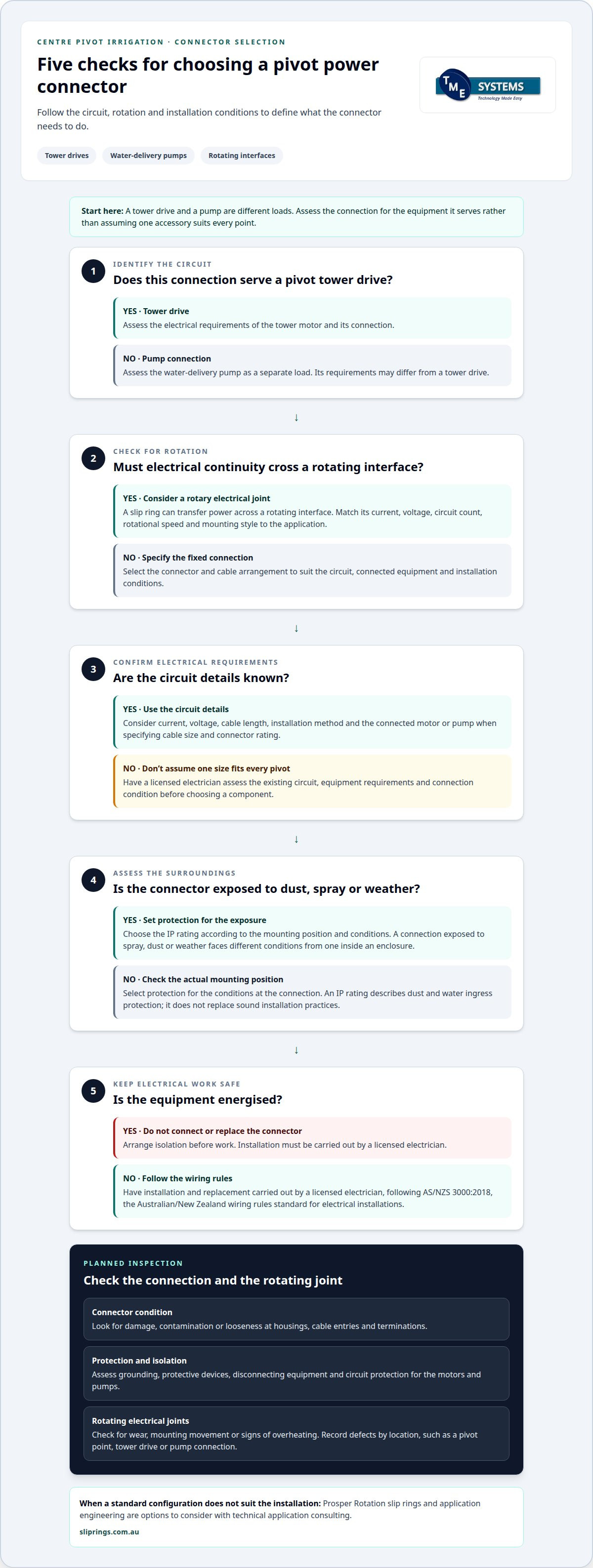
Never connect or replace a connector while equipment is energised. Arrange isolation and installation by a licensed electrician, following AS/NZS 3000:2018, the Australian/New Zealand wiring rules standard for electrical installations.
Electrical Accessories for Pivot Systems
Electrical accessories connect, control and protect the power circuits serving pivot motors and pumps. Choosing them carefully matters because the system combines a fixed electrical supply with moving machinery.
Depending on the installation, accessories can include conductors, connectors, control components, circuit protection and disconnecting equipment. Each has a distinct function: conductors carry power, connectors join circuits, and controls coordinate equipment operation.
Power may come from the grid or an on-site diesel or natural gas generator. Solar panels can also supply electricity. The source affects how the installation delivers power, while the motors’ electrical requirements determine the connector and circuit arrangement.
A pump connection and a tower-drive connection, for example, serve different equipment. Treat them as separate loads in the electrical design rather than assuming one accessory suits every point. A rotary electrical joint is relevant where continuity must be maintained across a rotating interface.
Weatherproof and Dustproof Connector Ratings
An IP rating defines the protection electrical equipment provides against dust and water ingress. It matters on a centre pivot because connectors may be exposed to outdoor conditions during operation and maintenance.
Choose protection according to the connector’s mounting position and exposure. A connection sheltered inside an enclosure faces different conditions from one exposed to spray, dust or weather. The required rating follows the installation environment, not the pivot system alone.
Dust or moisture entering a connector can affect its contact area and electrical continuity. A suitable enclosure and correctly fitted connection help limit exposure. The rating describes ingress protection, but does not establish suitability for every condition or replace sound installation practices.
During maintenance, inspect the connector body, cable entry and mating surfaces for damage or contamination. A cracked housing or poorly seated cable entry can undermine the protection provided by the rating.
Cable Sizes and Connector Ratings
Select cable size and connector rating to suit the circuit’s electrical load and installation conditions. Both must match the conductors and the equipment they serve.
The design takes into account current, voltage, cable length, installation method and the connected motor or pump. These factors influence conductor selection and the connector’s electrical rating. Without those details, no single cable size or connector rating applies to every pivot.
Also consider how the connector mounts and whether the circuit crosses a rotating interface. A rotary electrical joint must suit the rotation and circuit requirements as well as the electrical load. The cable termination and connector arrangement should match the installation’s wiring design.
For replacement work, an electrician can assess the existing circuit, equipment requirements and connection condition before selecting a suitable component. Matching the connector to the circuit helps ensure a compatible connection, rather than relying on physical fit alone.
Power reliability and maintenance
Reliable electrical power depends on sound connections, effective protection and maintenance that identifies faults early. On a centre pivot, the supply, motor connections, controls and rotating electrical joints work as one system. A fault at a tower connection, for example, can interrupt movement while the pump circuit remains operational.
Electrical safety comes first. Grounding conductors, circuit protection and disconnecting equipment help manage risks during operation and maintenance. Assess their condition and suitability as part of the irrigation system’s electrical installation, rather than treating them as minor accessories.
In Australia, electrical installation work must be considered against AS/NZS 3000:2018, the Australian/New Zealand wiring rules standard for electrical installations. A licensed electrician can assess the installation’s protection and isolation arrangements, then address defects before equipment returns to service. Don’t disconnect, replace or inspect live connections yourself.
During a planned inspection, an electrician can assess:
- Connector housings, cable entries and terminations for damage, contamination or looseness.
- Grounding and protective devices for condition and correct connection.
- Disconnecting equipment and circuit protection for the relevant motors and pumps.
- Rotating electrical joints for wear, mounting movement or signs of overheating.
Record defects by location, such as the pivot point, a tower drive or the pump connection. This helps maintenance staff track recurring faults and link them to a specific circuit. After a repair or component replacement, an electrician can verify the connection and protective arrangements before the pivot resumes operation.
Maintenance records can also help distinguish electrical faults from mechanical problems. If a tower drive stops while the pump continues running, for example, the affected equipment can help narrow the inspection. Note the location, affected equipment and operating conditions when the fault occurred. Regular attention to leaks, worn parts and alignment can also help prevent mechanical issues from being mistaken for electrical faults.
A useful maintenance record identifies the component, its observed condition and the corrective work. If the same connector or cable entry needs repeated attention, that pattern can focus a closer assessment of the mounting, movement or exposure at that point.
When recommissioning a pivot after electrical work, an electrician can assess the repaired connection and related protection before operation resumes. This ties maintenance findings to the actual circuit and helps ensure the work addresses the fault, not just its visible symptom.
A Nebraska rural power supplier’s inspections found that nearly 40 percent of the inspected systems did not have a ground rod installed. A Nebraska state electrical inspector classified 10 of 77 inspected irrigation systems as lethal, 38 of 77 as definitely hazardous and 29 of 77 as potentially hazardous. These findings underline why grounding and protective arrangements should be verified by a qualified electrician, not assumed to be present or effective.
Two of the five electrocutions discussed were directly related to improperly installed and grounded electrical equipment. Treat any suspected grounding defect, damaged cable or exposed connection as a reason to keep people clear and arrange prompt professional assessment. Before restarting equipment after work, confirm that the electrician has checked the relevant installation and documented the corrective action.
What power connectors are used for centre pivot irrigators in Australia?
Centre pivot panels can use fixed terminal connections, detachable plug-and-socket connections, or a rotary electrical joint where the circuit crosses moving parts. The suitable arrangement depends on the panel interface and the equipment it serves. No single plug configuration can be assumed to fit every pivot installation.
A fixed termination connects conductors directly to terminals inside a panel or enclosure. It suits a connection intended to stay in place during normal operation. A detachable plug and socket allows equipment to be disconnected at its interface, which can be useful when a motor or component needs to be separated from the panel connection.
Rotating sections have a different requirement. A slip ring assembly provides electrical paths across the rotating interface, with its configuration selected for the circuits involved. For example, a pivot design may need separate paths for power and control signals. The arrangement must suit the panel wiring and the functions carried through the rotating connection.
Compatibility involves more than the plug’s outline. The panel and connector need matching contact arrangements, conductor terminations, electrical characteristics and physical mounting. A plug that mates mechanically may still be unsuitable if its contact layout or electrical capacity does not match the circuit. Treat the connector and panel as parts of the same interface design.
Use the panel documentation and equipment wiring information to identify the connection type. These documents can show whether the connection is hard-wired, detachable or routed through a rotary assembly. For a replacement, the existing interface provides useful details, but the panel and connected equipment requirements still guide the choice.
Common arrangements include:
- Panel terminals: conductors terminate inside the control enclosure.
- Plug-and-socket connections: a detachable interface joins the panel wiring to equipment.
- Rotary electrical joints: a slip ring assembly carries circuits across rotating sections.
These arrangements serve different points in an irrigation system and are not interchangeable. A fixed panel termination, for instance, does not perform the same function as a rotary assembly between stationary and moving sections. The panel layout, connected equipment and system movement determine which type is relevant.
For Australian installations, base the selection on the actual panel and machine configuration. An electrician or application engineer can interpret the wiring information, identify the connection interface and assess the appropriate connector arrangement. This gives the design a clear basis before components are selected or replaced.
How do weatherproof and dustproof ratings affect connectors used on center pivots?
An IP rating affects how a connector is specified, assembled and maintained, not just which component is purchased. The complete connection may include a plug, socket, cable entry and enclosure.
Check how the rating applies to the connector assembly. Product documentation may describe an individual component or a particular assembled configuration. For a plug-and-socket pair, confirm that the stated protection applies when the parts are connected. A loose cap or an unconnected socket may have different protection from the mated interface.
Assembly details matter. A seal can be displaced, a cable gland may not suit the cable, or a locking feature may remain unsecured. Each issue changes the path through which dust or moisture could enter. Follow the product’s assembly instructions, including specified cable preparation and correct seal positioning.
Maintenance can affect connectors when their interfaces are disturbed. Removing a plug, opening an enclosure or replacing a cable entry changes the assembled connection. After work, inspect the mating surfaces and sealing components, then reassemble the connection as directed. A damaged seal or cracked housing needs attention before the equipment returns to operation.
Replacing only a plug on a tower connection, for example, can create a mismatch with the existing socket. The connector may still mate, but the combined parts might not have the same documented protection. Treat the plug and socket as a matched interface, and keep the relevant assembly information with the equipment records.
During design review, record:
- Component pairing: the plug and socket types specified for the connection.
- Assembly conditions: required seals, caps, cable entries and locking arrangements.
- Maintenance changes: parts opened, replaced or disturbed during inspection.
- Documentation: the configuration to which the stated rating applies.
These records help maintenance staff restore the intended connector arrangement after servicing. They also make it easier to identify when a replacement changes the interface, rather than assuming a physically similar part retains the same documented protection.
On a centre pivot, connectors may be opened during electrical work or component replacement. The rating remains useful only when the installed assembly follows its documented configuration. An electrician can assess the reassembled connection and associated enclosure as part of system maintenance.
What cable size and connector rating are needed for a centre pivot irrigator?
A cable size or connector rating cannot be chosen from the machine name alone. Read the equipment and connector documentation together, then match the cable specification to the connector’s permitted conductor range. This helps prevent a mismatch, such as a cable fitting poorly in the terminal or a contact failing to accommodate its conductor.
Cable cross-section is expressed in square millimetres, while connector documentation may state a conductor range and a current rating. These describe different parts of the connection. The cable must terminate securely, and the connector’s electrical rating must apply to the circuit using it. A terminal that is physically compatible does not, by itself, make the complete connection suitable.
Pay attention to the termination design. Screw terminals, crimp contacts and plug contacts each require compatible conductor preparation and connection methods. For example, a stranded conductor may need a termination suited to the selected terminal. Connector documentation should identify suitable conductor types and termination arrangements; follow those details during installation.
Movement also affects cable construction. A cable routed along a moving tower may need to accommodate repeated flexing, while a stationary panel connection has a different mechanical role. The cable must suit its route, and the connector must secure it without placing undue strain on the termination. Routing and support help prevent movement from pulling conductors at their contacts.
For a specification review, compare the following information from the equipment and connector documents:
- Cable specification: conductor cross-section, conductor type and insulation details.
- Termination compatibility: supported conductor range and required preparation at the contact.
- Connector rating: the stated electrical limits and the circuits to which they apply.
- Mechanical arrangement: cable entry, strain relief and any movement along the route.
Keep these details together for each circuit rather than relying on a general description of the pivot. A replacement connector, for example, should suit the actual conductor and termination, not merely resemble the removed component. Documentation can also clarify whether a connector is intended for a fixed termination or forms part of a rotary assembly.
A qualified electrical professional can assess the complete connection against the equipment documentation and installation design. This review considers the cable, termination and connector as a coordinated assembly. If the arrangement includes a slip ring, its circuit configuration must also align with the conductors and functions passing through the rotating interface.
TME Systems
TME Systems Pty Ltd helps match slip ring requirements to the electrical and mechanical demands of centre pivot applications. For connections transferring power across a rotating interface, selection depends on factors such as circuit count, current, voltage, speed and mounting style.
Options include Mercotac Slip Rings, Meridian Laboratory Slip Rings, BGB Innovation Slip Rings and Prosper Rotation Slip Rings. The suitable option depends on the application’s power and signal requirements and its mounting arrangement.
For an application discussion, prepare the equipment requirements, circuit details, operating speed and available mounting space. These details help narrow the selection to a connector configuration suited to the pivot’s rotating interface.
Contact TME Systems Pty Ltd to discuss slip ring requirements for your centre pivot system.
Plan the next connector decision
Use the system design to define what the rotating connection must carry and how it will be mounted. A power connector for centre pivot irrigators must suit the specific circuit and operating conditions, not simply match an existing connector’s shape. This distinction helps guide the engineering discussion, especially when an installation or replacement changes the electrical or mechanical arrangement.
TME Systems Pty Ltd offers Mercotac Slip Rings, Meridian Laboratory Slip Rings and BGB Innovation Slip Rings. Discuss your application with TME Systems Pty Ltd to relate these options to your requirements, including circuit count, electrical load and mounting style.
Bring the equipment details and connection requirements into the conversation, then choose a suitable direction for your project. Contact TME Systems Pty Ltd about pivot power and take the next step with a clearer connector specification.
Frequently Asked Questions
Which connector types and plug configurations are compatible with centre pivot irrigator panels?
Compatibility depends on the panel’s connection layout and the circuit’s electrical requirements. A panel with a dedicated socket needs a matching plug configuration, while hard-wired connections use suitable cable terminations. Identify the connector’s pin arrangement, earthing provision, voltage and current requirements, and enclosure conditions. A licensed electrician can compare these details with the panel documentation and select a compatible connection without assuming one plug suits every pivot.
What are common power connector faults on centre pivot irrigators and how can they be prevented?
Common faults include loose terminations, damaged insulation, corrosion, contaminated contacts and cable strain near the connector. Repeated movement, for example, can stress a cable where it enters a tower-mounted enclosure. Preventive maintenance includes examining connector bodies, cable entries and terminations for deterioration, then arranging repairs through a licensed electrician. Correct assembly and protection suited to the installation environment also help limit ingress and connection damage. Isolate equipment before inspection or maintenance.