Smaller rotary connectors are not simply a matter of shrinking the housing. The future trends in rotary connector technology for 2026 centre on balancing compact designs with heat resistance, reliable signal and power transfer, and the demands of increasingly connected equipment.
Engineers are weighing how material choices affect heat management and service life, while miniaturisation increases pressure on mounting space and circuit requirements. Sustainability is also influencing design decisions, alongside interest in IoT-enabled monitoring that can provide operational data from rotating equipment.
This article explores how these developments may shape rotary electrical connectors, including heat-resistant materials, smaller form factors, sustainability considerations and smart integration. Application requirements remain central: current, voltage, rotational speed, circuit count, mounting style and operating environment all influence which design is suitable. The aim is to help Australian engineers and procurement teams assess emerging technologies against their equipment’s needs.
Key Takeaways
- Assess heat-resistant materials alongside operating temperature and thermal management needs, not as a standalone upgrade.
- Match a smaller connector’s form factor and circuit count to the available space and the power and signal paths required.
- Consider how IoT-enabled diagnostics and monitoring could support maintenance decisions for rotating equipment.
- Compare fibre-optic rotary joints and high-speed data connectors with contactless power transfer based on the signals or energy your application must transmit.
- Use current, voltage, speed, mounting style and environmental conditions to narrow the connector options for your equipment.
Advanced materials and heat resistance
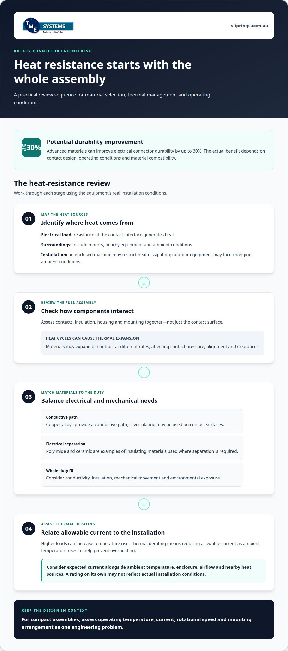
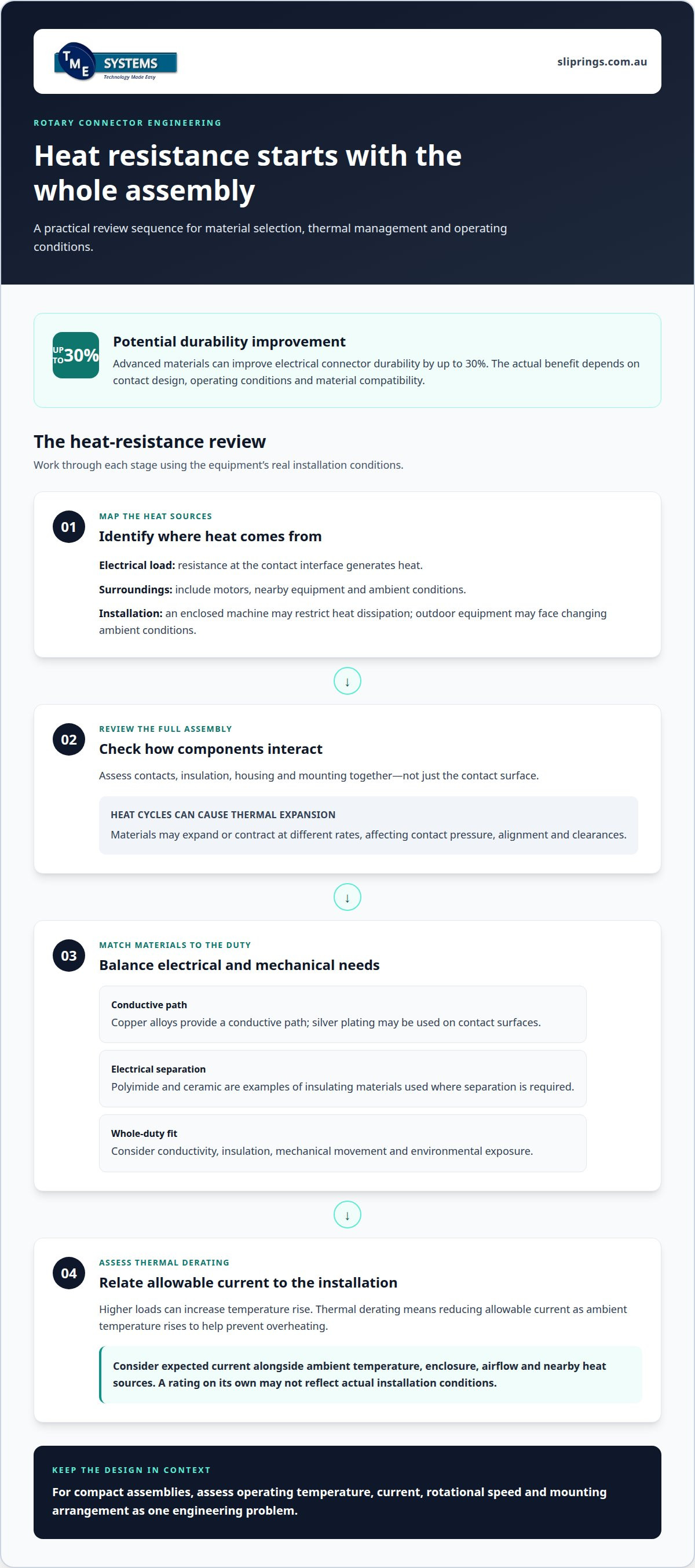
Heat-resistant materials are becoming a key consideration in rotary connector design. Advanced materials can improve electrical connector durability by up to 30%. The actual benefit depends on contact design, operating conditions and material compatibility. A connector exposed to heat from nearby machinery faces different demands from one operating outdoors in Australian sun. Engineers therefore assess the full assembly, not just the contact surface.
Conductive and insulating materials each affect performance. Copper alloys provide a conductive path, while silver plating may be used on contact surfaces. Polyimide and ceramic are examples of insulating materials used where electrical separation is required. Materials respond differently to heat, mechanical stress and environmental conditions, so selecting a component in isolation can overlook interactions among contacts, insulation and housing materials.
Temperature changes also cause thermal expansion. As a connector heats and cools during operation, its materials may expand or contract at different rates, affecting contact pressure, alignment and clearances. For example, a rotating assembly near a motor may experience heat from both its electrical load and nearby equipment. Engineers assess these combined conditions when evaluating thermal management and connector suitability.
Current is another key factor. Electrical resistance generates heat at the contact interface, and higher loads can increase temperature rise. Thermal derating means reducing allowable current as ambient temperature rises to help prevent overheating. A design must account for expected current alongside the enclosure, airflow and nearby heat sources. A rating considered on its own may not reflect the connector’s actual installation conditions.
Material selection also affects the balance between electrical and mechanical requirements. Contacts must conduct current while maintaining reliable contact during rotation. Insulation must separate circuits under expected thermal conditions, and housing materials must suit the installation and maintain component alignment. These considerations apply to both power circuits and signal paths, although their electrical requirements differ.
- Map heat sources: identify heat from current, motors, nearby equipment and ambient conditions.
- Review the full assembly: assess contacts, insulation, housing and mounting together.
- Match materials to duty: consider conductivity, insulation, mechanical movement and exposure.
- Assess thermal derating: relate allowable current to ambient temperature and installation conditions.
For Australian equipment, this process should reflect the actual installation rather than a generic environment. An enclosed machine can restrict heat dissipation, while outdoor equipment may face changing ambient conditions. The future trends in rotary connector technology for 2026 place greater emphasis on compact assemblies, making thermal management important within limited space. A sound material choice begins with operating temperature, current, rotational speed and mounting arrangement, considered as one engineering problem.
Connector miniaturisation
Smaller rotary connectors can free space around shafts, motors and compact machinery, but reducing the housing size is only part of the challenge. Engineers must fit the required circuit count, insulation, contacts and mounting features into less space. A robot joint, for example, may need a compact assembly that carries power and signals while allowing adjacent components to move.
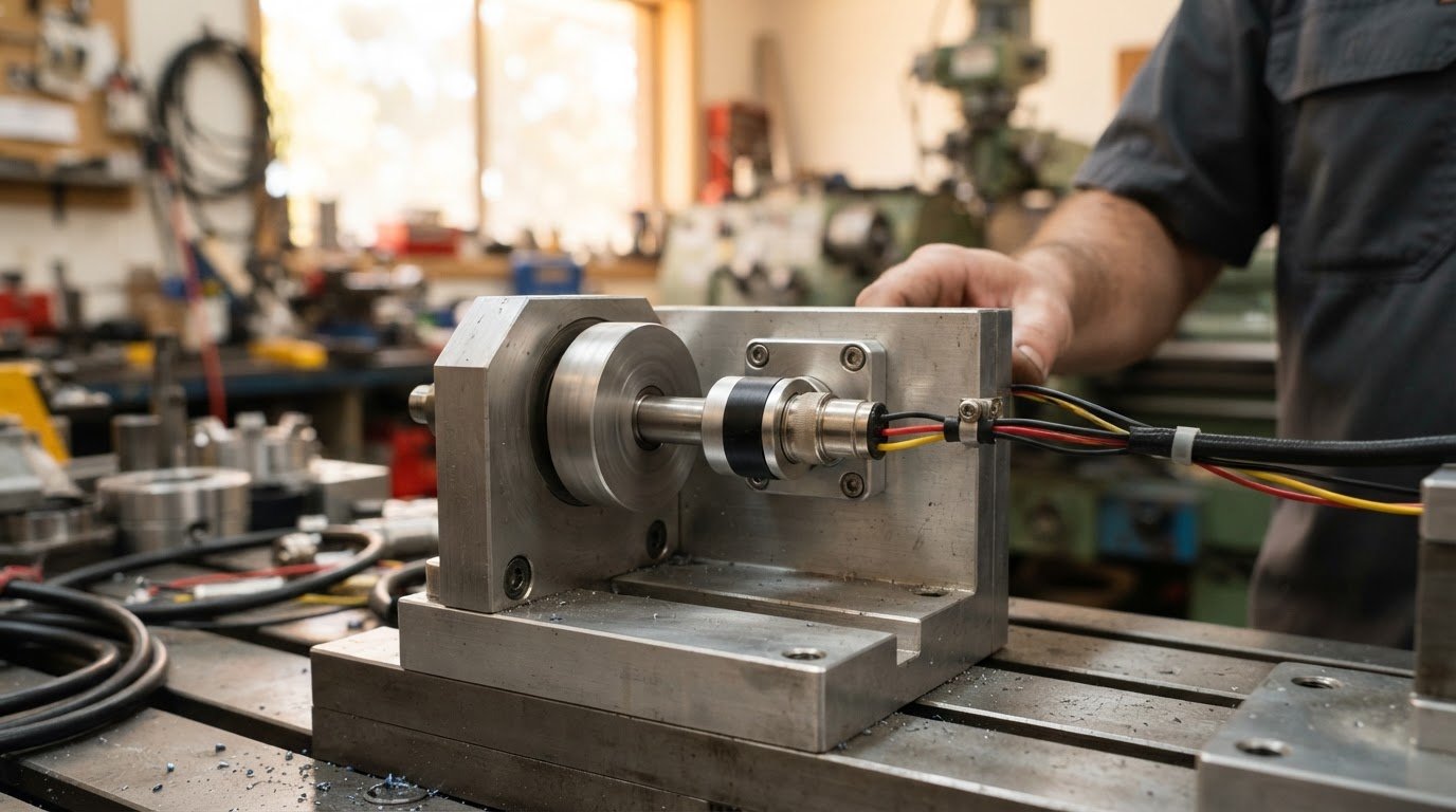
Form factor determines how a connector fits the machine. A through-bore slip ring mounts around a shaft, while a capsule slip ring suits end-of-shaft mounting. The choice depends on centre space, shaft geometry and nearby services. Miniaturisation can complicate packaging when the design also needs a high circuit count, mixed power and signal paths, or extra mechanical clearance.
Smaller dimensions also make heat dissipation and installation access important. Closely packed components can restrict airflow, while confined mounting positions can complicate cable routing. Assess the connector as part of the surrounding assembly. A compact design must still provide suitable electrical separation, alignment and access for installation and maintenance.
Slip rings maintain electrical continuity through moving contacts, while contactless rotary connectors transfer energy without sliding electrical contacts. Contactless designs avoid wear at those contacts, but reliability and maintenance for either approach depend on operating conditions and system design. Contactless systems still require attention to their electronics and alignment.
Applicable standards depend on the connector’s function and its installation. AS/NZS 3000:2018 is the Australian/New Zealand wiring rules standard for electrical installations. ISO and IEC standards are also relevant to fibre-optic rotary connector compliance considerations, but neither label alone establishes suitability for every rotary connector.
For 2026 designs, compare specifications against the equipment’s actual duty. Rotational speed rating, bandwidth, current, voltage, circuit count and expected service life all matter. A connector carrying Ethernet signals has different transmission requirements from one carrying power. Mounting dimensions and operating conditions also affect performance in a compact assembly.
Miniaturised designs can face contact wear, heat build-up, contamination, vibration and electrical interference. Network-connected monitoring also brings cybersecurity considerations, including access control and protection of connected systems. Address risks at both the rotary interface and the equipment communicating through it.
Australian applications include automation, robotics, wind power systems and crane slewing equipment. Industrial suppliers serving these sectors provide rotary connectors from specialist manufacturers, with selection shaped by the required current, speed, mounting style and environment. The specific supplier depends on the application and product requirements.
- Confirm fit: account for shaft dimensions, mounting position and cable routing.
- Match transmission needs: specify power, signals, bandwidth and circuit count.
- Assess the environment: consider heat, vibration, contamination and maintenance access.
Smart connectors and IoT integration
IoT integration is shifting rotary connector design towards better visibility of operating conditions. The connector still transfers power or signals between stationary and rotating equipment. Monitoring can add information about the connected system, helping operators assess performance and plan maintenance. Industry 4.0 protocols support real-time monitoring, predictive analytics and remote operation of rotary actuators.
A rotary connector is not automatically a smart device. Monitoring depends on sensors, data-acquisition hardware and software elsewhere in the assembly. For example, a temperature sensor near a slip ring can send readings to a controller, while current measurements can help reveal changes in electrical load. The controller can then send relevant readings to a local system or authorised remote interface.
Smart diagnostics and real-time monitoring are potential growth areas for industrial rotary electrical connectors. Their value depends on the condition being monitored. Temperature trends may help identify changing thermal conditions, while signal interruptions can point to contact or wiring issues. Readings need context: a pattern compared with the equipment’s normal operating state is more informative than a single measurement.
Before selecting a connector, map the information path. Identify the condition that matters, such as heat, vibration or signal interruption. Establish where the sensor will sit and how its data will reach the control system. Then define who can access readings and what action should follow an alert. This ties monitoring to a maintenance decision instead of collecting data without a clear purpose.
IoT and Industry 4.0 protocols can support remote operation of rotary actuators, but connectivity adds integration work. The system must handle rotating-interface signals alongside the equipment’s existing controls. Engineers consider bandwidth, electrical noise, data continuity and the consequences of a lost connection. For a robotic cell, for instance, a monitoring signal should not be confused with a command controlling movement.
Connected equipment also needs sensible access controls. Limit network access to authorised users, and separate monitoring data from control functions where the system design requires it. A local controller can process readings before forwarding selected information, which may reduce unnecessary data traffic and clarify which system responds to a fault.
- Set a purpose: choose a measurable condition linked to maintenance or operation.
- Trace the data path: map sensors, controllers, protocols and receiving systems.
- Define response logic: state what an operator or control system does with an alert.
For 2026 planning, treat IoT integration as a system-level requirement, not a connector feature by itself. The connector’s circuit count, signal needs and operating environment must fit the monitoring architecture. Matching those elements helps teams assess whether real-time diagnostics can support their equipment without complicating essential power or control paths.
Efficient local controllers manage data transfer when only selected information is needed. The smart connectors market is projected to grow at a compound annual growth rate of 15% and reach $5 billion by 2026, a trend monitored closely by specialists such as TME Systems Pty Ltd.
How are fibre-optic rotary joints and high-speed data connectors improving in 2026?
Fibre-optic rotary joints transfer optical signals between stationary and rotating equipment, maintaining data flow across a rotating interface without twisting the fibre cable. In wind power systems, they support communication between fixed structures and rotating components. Industrial automation and robotics also use them to keep control data moving during rotation.
The design priority is signal continuity throughout rotation. Fibre alignment matters because the optical path must remain coupled as components move. Mechanical runout, vibration and contamination can affect alignment. In a robotic arm, for example, the rotary joint must suit the joint’s movement and the communication system’s requirements.
Fibre-optic interfaces can be relevant where electrical transmission faces constraints such as electromagnetic interference. Optical signals carry data without a conductive path, but that does not make every fibre-optic joint suitable for every machine. Engineers still need to assess the data type, rotation, mechanical fit and environment around the rotating assembly.
High-speed data transmission depends on more than the rotary joint. The stationary and rotating equipment must have compatible interfaces, and the data path must meet the system’s bandwidth requirements. Ethernet and HDMI signals, for example, have different transmission requirements from basic control signals. Start connector selection with the data being transferred, not a general claim about speed.
In wind turbines, continuous communication between stationary and rotating sections can support equipment monitoring and control. In factory automation, a robot may need to exchange data with fixed control equipment as its joint rotates. Fibre-optic rotary connectors help maintain this communication path. The application determines how the joint integrates with cable routing and the surrounding mechanical assembly.
The global fibre-optic rotary connector market is forecast to grow at an annual rate of 5.9% from 2026 to 2033. That forecast points to expanding market interest, not a performance rating for a particular connector. For equipment designers, the practical consequence is a stronger need to define data and mechanical requirements before selecting an interface.
ISO and IEC standards are relevant to compliance considerations for fibre-optic rotary connectors, but applicable requirements depend on the equipment and installation. An engineering review should distinguish connector performance from system-level compliance. A joint’s data-transfer function alone does not establish that the complete machine meets its requirements.
- Define the data path: specify the signals and interfaces used on both sides.
- Assess movement: account for rotation, alignment, vibration and cable routing.
- Review the complete system: consider the joint alongside its controls and installation.
In 2026, the useful direction is closer integration between optical transmission and rotating machinery. Fibre-optic rotary joints support wind power communication, while industrial control and robotics depend on continuous data flow. Selecting a suitable design means matching those functions to the application, rather than assuming one connector covers every data requirement.
What are the latest developments in contactless rotary power transfer and inductive slip rings?
Inductive rotary power transfer sends energy across a small gap between stationary and rotating components. A stationary coil creates a changing magnetic field, which a rotating coil receives. This contactless arrangement avoids sliding electrical contacts but requires power electronics and suitable coil alignment.
The term “inductive slip ring” is often used for this contactless approach, although it differs from a conventional slip ring. A conventional slip ring transfers electricity through physical contacts; an inductive rotary transformer transfers power across an air gap. The right choice depends on the required load, available space, operating conditions and system design.
Removing sliding contacts can reduce contact wear and the maintenance associated with those contacts, but it does not eliminate every maintenance requirement. Bearings, seals, alignment and power electronics still need consideration. For example, a rotating assembly exposed to vibration may need a mechanical design that maintains the gap between transmitter and receiver coils.
Power transfer also involves integration trade-offs. Coils need sufficient space and correct alignment, and the system must manage heat from electrical losses. Power electronics must suit the required output and the rotating equipment’s operating cycle. Assess the complete interface, including the load, enclosure, cooling path and control system.
Contactless transfer can suit applications where avoiding electrical contact is a priority. A sealed rotating assembly, for example, may benefit from transferring power without exposed sliding contacts. A conventional slip ring may be more appropriate where direct conductive paths, multiple circuits or established system requirements matter. Neither method is universally preferable.
Inductive transfer does not automatically carry every signal a machine needs. If the rotating assembly requires both power and data, engineers must define separate transmission paths or select an integrated arrangement. They should consider signal type, bandwidth, electrical noise and how the rotating equipment communicates with stationary controls.
Compare the approaches against the application rather than the technology label:
- Contactless induction: assess coil alignment, air gap, power electronics and heat.
- Sliding contacts: assess circuit count, current, signal needs and contact maintenance.
- Combined requirements: map power and data paths across the rotating interface.
In 2026, contactless rotary power transfer is best treated as an application-specific design option, not a universal replacement. Start with the required power, available mounting space, operating environment and maintenance priorities. For help assessing rotary connector options against those requirements, discuss your application.
Wind power generation is the fastest-growing application segment by revenue for industrial rotary electrical connectors. Separately, wind power is the fastest-growing fibre optic rotary connector application segment by revenue. Fibre optic rotary connectors support communication between stationary and rotating components in wind power systems. These facts distinguish the power-transfer role of an inductive rotary transformer from the communication role of a fibre optic rotary connector. Where a wind power system needs both functions, treat power and communication as distinct interface requirements rather than assuming contactless power transfer also carries data.
TME Systems
TME Systems Pty Ltd helps Australian engineers assess rotary electrical joints for their equipment’s operating requirements. These joints transfer electrical power and signals between stationary and rotating parts. Application engineering supports selection by assessing circuit count, current, voltage, speed, mounting style and environment, including requirements for liquid metal slip rings, which use conductive liquid metal to maintain electrical continuity without brush contact.
The available range includes Mercotac Slip Rings, Meridian Laboratory Slip Rings, BGB Innovation Slip Rings and Prosper Rotation Slip Rings. The right option depends on how the connector must fit and perform within the complete assembly.
For a selection discussion based on your application requirements, contact TME Systems Pty Ltd.
Turn technology trends into a practical design decision
Planning for the future trends in rotary connector technology in 2026 means translating emerging designs into requirements for a real machine. Before specifying a connector, define the conditions it must operate under and the outcomes the rotating interface must support. That gives engineering and procurement teams a clearer basis for assessing design options, including where established slip ring configurations remain appropriate.
The next step is to match your application requirements with suitable solutions. TME Systems Pty Ltd supplies Mercotac Slip Rings, Meridian Laboratory Slip Rings and BGB Innovation Slip Rings, with technical application consulting to help assess suitability. Share your operating requirements with TME Systems to discuss the considerations that matter for your equipment.
Discuss rotary connectors with TME Systems Pty Ltd and take the next step towards a well-matched design.
Frequently Asked Questions
What are the main rotary connector technology trends forecast for 2026?
Alongside compact designs and connected monitoring, sustainability is influencing connector development. The global eco-friendly connector market could reach $10 billion by 2026. For equipment teams, the practical task is to assess material choices against the operating environment and assembly requirements, rather than treating an environmental label as proof of suitability. Consider recyclability, material compatibility and the connector’s role within the complete machine.
How are rotary connectors being miniaturised for robotics, cobots and medical devices?
Start by defining the connector’s installation envelope and the equipment’s required electrical paths. In a robotic wrist, account for joint movement, cable exit direction and connections to end-of-arm tools. A collaborative robot may also need separate paths for power and sensor signals. For medical equipment, the connector’s physical fit and electrical interfaces must suit the device layout and intended operating conditions.
Which Australian and international standards and certifications apply to rotary connectors in 2026?
AS/NZS 3000:2018 - Australian/New Zealand wiring rules standard for electrical installations., while ISO and IEC standards are relevant to fibre-optic rotary connector compliance. Applicability depends on the connector’s function and installation; a standards label alone does not establish suitability.