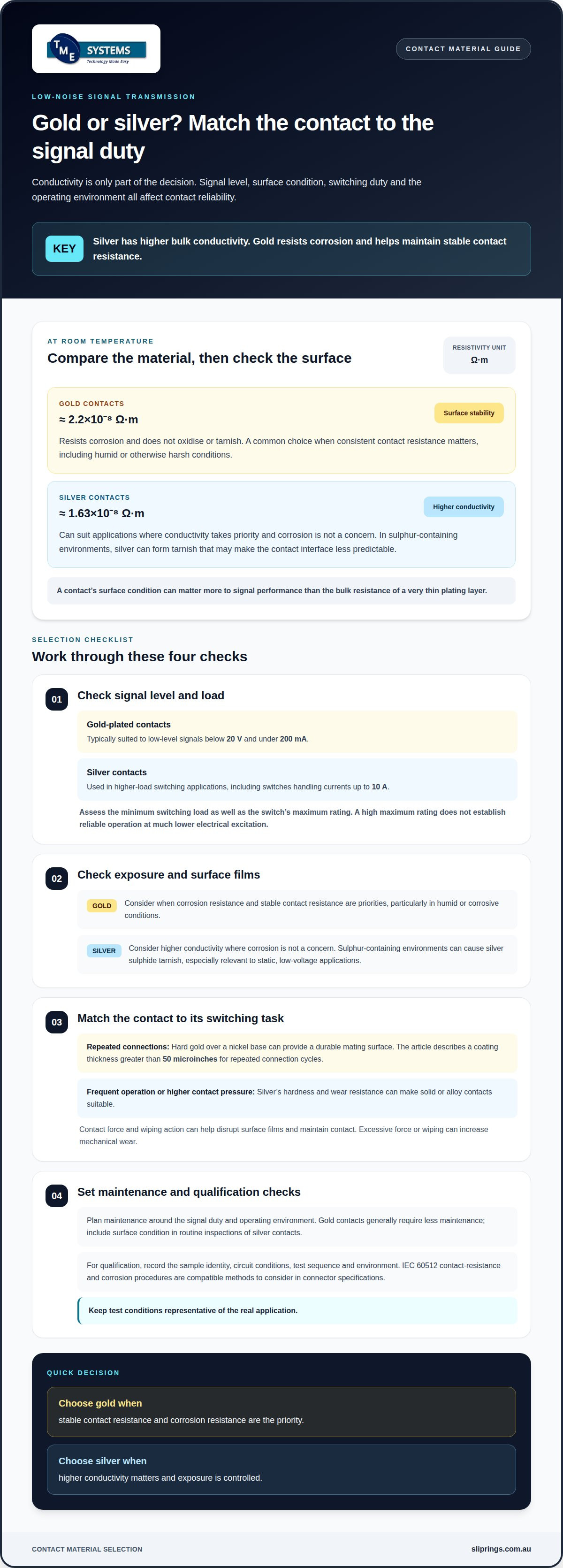
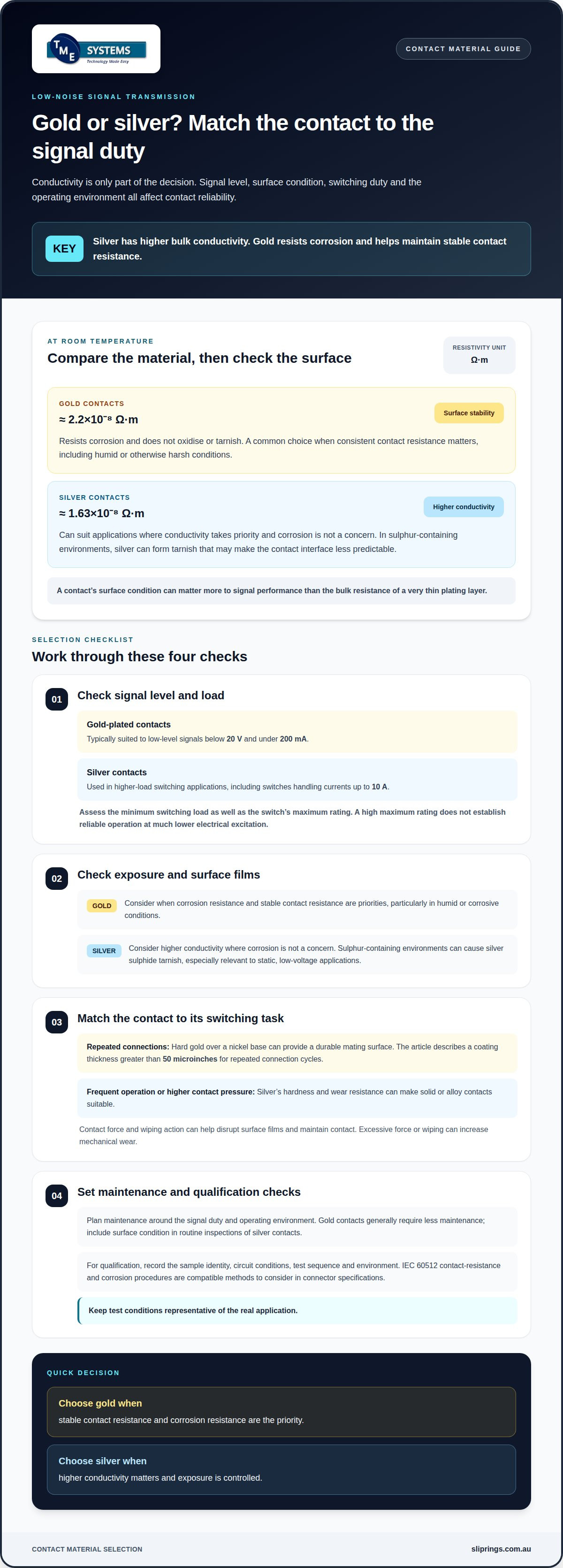
Silver conducts electricity better than gold, but that doesn’t automatically make it the better contact for a low-level signal. Choosing gold vs silver contacts for low-noise signal transmission usually favours gold when stable contact resistance matters, while silver’s higher conductivity can suit applications where that property takes priority.
Conductivity matters when comparing contact materials, but the contact surface matters too. Silver can tarnish in polluted or sulphur-containing environments, while gold resists corrosion and avoids oxide layers that can interfere with conduction.
This comparison explains how the metals differ electrically, how surface films and operating conditions affect signal reliability, and where each material is commonly used. It also covers the trade-offs when selecting contacts for low-voltage signals, helping you match the material to the electrical load and environment rather than choosing on conductivity alone.
Key Takeaways
- Choose contact material by weighing signal level, conductivity and environmental exposure, not conductivity alone.
- Consider how tarnish and corrosion may affect contact stability, particularly in low-level signal applications.
- Match contacts to the switching task: signal transmission and power switching place different demands on the contact surface.
- For rotating connections, assess circuit count, electrical requirements, speed, mounting style and operating environment together.
- Prosper Rotation slip rings and technical application consulting can help align a rotary electrical connection with the application requirements.
Silver vs Gold Contacts: How Are They Different?
Silver has higher bulk conductivity, but low-noise signal transmission also depends on the contact surface. Gold resists corrosion, while silver can tarnish in sulphur-containing environments.
Gold contacts
Gold contacts are selected for surface stability, not for the highest bulk conductivity. At room temperature, gold’s resistivity is approximately 2.2×10⁻⁸ Ω·m, compared with silver’s 1.63×10⁻⁸ Ω·m. Gold does not oxidise or tarnish, helping maintain consistent contact resistance when surface films could disrupt a low-level signal. This ability to resist corrosion makes gold a common choice in humid or otherwise harsh conditions.
Silver contacts
Silver contacts offer greater conductivity, but their surface can change with exposure. In sulphur-containing environments, silver can form silver sulphide tarnish, which may increase contact resistance and affect very low-voltage signals, particularly in static applications. Although tarnish remains fairly conductive, it can make the contact interface less predictable. Reliable low-level signals need controlled contact force to maintain contact, along with enough wiping action to disrupt surface films. Excessive force or wiping can increase mechanical wear.
| Contact material | Room-temperature resistivity | Surface behaviour | Typical consideration |
|---|---|---|---|
| Gold | Approximately 2.2×10⁻⁸ Ω·m | Resists corrosion and does not form oxide layers | Stable contact resistance for low-level signals |
| Silver | Approximately 1.63×10⁻⁸ Ω·m | Can form sulphide tarnish in sulphur-containing environments | Higher conductivity, with surface condition to consider |
Environmental exposure changes the comparison: humid conditions and corrosive gases favour gold’s corrosion resistance, while silver can suit applications where conductivity is the priority and corrosion is not a concern. Contact resistance can matter more than the bulk resistance of a very thin plating layer, making surface condition central to signal performance.
Choose gold when stable contact resistance in a corrosive environment is the priority. Choose silver when higher conductivity matters and exposure is controlled.
Applications in Connectors and Switching Equipment
Contact material selection depends on voltage, current and switching duty. Gold-plated contacts are typically suited to low-level signals below 20 V and under 200 mA, while silver contacts are used in higher-load switching applications.
Gold-plated contacts suit PCB edge connectors, telecommunications equipment, medical devices and aerospace systems. These applications may carry low-level control or signal inputs, where a stable connection matters more than maximum current capacity. Hard gold over a nickel base can provide a durable mating surface for repeated connection cycles, including in frequently connected and disconnected connectors.
Silver contacts are common in circuit breakers, industrial relays, power switches and automotive electrical systems. They suit higher-current applications, with silver contacts used in switches handling currents up to 10 A. For high-current switching, conductivity and heat dissipation are key selection factors. Silver contacts are typically associated with higher-voltage switching, starting around 20 V.
Repeated switching wears contact surfaces, so the finish and contact design matter. Hard gold plated to a thickness greater than 50 microinches over a nickel base can provide a durable coating for repeated connection cycles. Silver contacts also have high hardness and good wear resistance, making silver solid or alloy contacts suitable for frequent operation or higher contact pressure.
For a low-level signal circuit, assess its minimum switching load, not just the switch’s maximum rating. A switch rated for a high load may not operate reliably at much lower electrical excitation. In equipment exposed to unfavourable weather, silver plating may be unsuitable for connectors used primarily outdoors. Match the material to the actual load, switching frequency, connector use and environment.
Contact Maintenance and Material Selection
Plan maintenance around the signal duty and the contact’s operating environment. Gold contacts generally require less maintenance than silver contacts, which can simplify upkeep where consistent low-level performance is critical. In an industrial control circuit, document the expected load, switching pattern and exposure conditions before choosing a material.
For silver contacts, include surface condition in routine inspections. Silver sulphide tarnish can affect contact resistance, particularly in static, low-voltage applications. Look for contamination or contact degradation rather than relying only on a switch’s maximum electrical rating. That rating does not establish reliable operation at much lower excitation.
Gold’s corrosion resistance can support longer-term stability in humid conditions or corrosive atmospheres. It does not remove the need to assess contact wear, the mating surface and the full circuit duty. A gold-plated surface may also be affected if porosity or chemical exposure allows the underlying material to corrode, as documented in a NASA investigation.
For qualification, agree on an acceptance method and record the sample identity, circuit conditions, test sequence and environment. IEC 60512 contact-resistance and corrosion procedures are compatible methods to consider in connector specifications. Keep the test conditions representative of the real application. A high-current switching test can change the contact surface, so it may not represent a low-level intermittent fault.
Choose between these metals by balancing maintenance needs, reliability and electrical duty. Gold suits designs where stable contact behaviour and reduced maintenance are priorities. Silver suits designs where its electrical properties fit the load and the environment supports dependable operation. Consider the actual contact system, not just its visible finish.
Choosing Contacts for Low-Voltage Signal Transmission
Start with the circuit’s actual voltage and current, then consider signal level and operating environment. Gold-plated contacts are commonly suited to low-level signals below 20 V and under 200 mA. Silver contacts typically require around 20 V and 50 mA for reliable operation, making them less suitable for very small electrical excitation. A switch’s maximum rating alone doesn’t establish reliable performance at a lower load.
Comparing gold vs silver contacts for low noise signal transmission starts with the minimum signal the contact must carry. Gold-plated contacts are preferable to solid silver contacts when a circuit carries low-level signals or faces corrosive conditions. Gold can operate at voltages as low as 1 V and currents as low as 5 mA. Silver offers higher conductivity, but its surface condition can affect contact resistance in static, low-voltage circuits.
For gold vs silver contacts for low noise signal transmission, the connector type and finish should suit the signal path and mating arrangement. Hard gold over a nickel base is recommended for the mating area of line-level or microphone-level audio connectors. Gold finishes are also used on PCB edge connectors and telecommunications equipment. Select the finish based on the contact interface, not just the visible terminal surface.
Use this selection sequence for a control or measurement circuit:
- Record the circuit’s minimum and normal voltage and current, including its switching load.
- Identify whether the contact remains static or switches, and whether the environment is humid or exposed to corrosive gases.
- Match the finish to the duty: gold-plated contacts for low-level signals, or silver where higher conductivity suits the load.
- Assess the contact surface itself. A visible screw-terminal finish does not identify the internal switching contact.
Gold-plated contacts have a stated maximum voltage range of about 24 V. Treat that as a material-selection limit, not proof that every contact suits every circuit. For signals below 20 V, assess the actual minimum switching load alongside the connector finish.
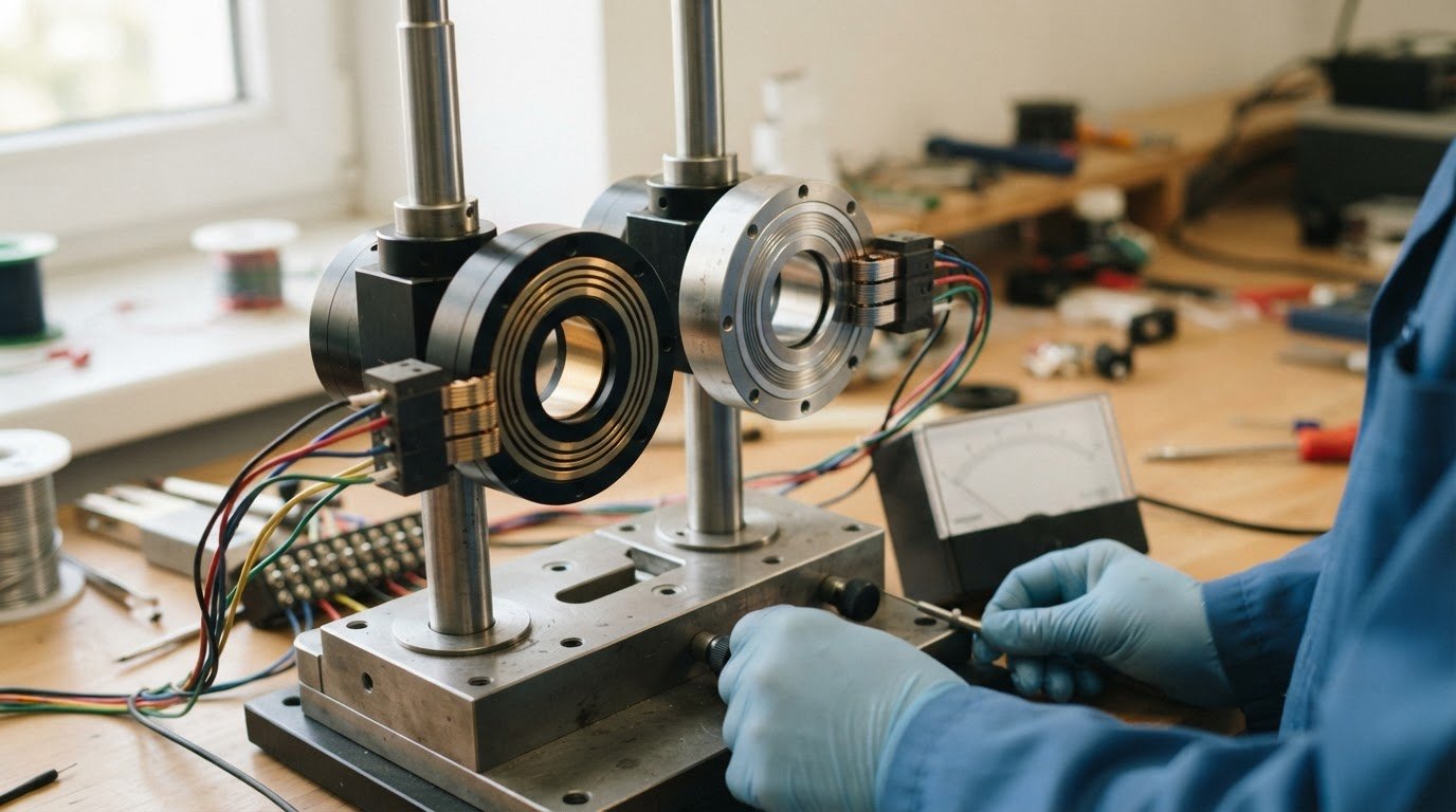
Silver and Gold Electrical Contact Materials
An electrical contact is the conductive surface where two circuit components meet. Contact materials may be solid metals, alloys or thin plating over a supporting layer. This construction affects the interface: bulk metal properties alone cannot describe how a sensitive signal behaves at the mating surface.
Gold plating is commonly applied over nickel, which supports the softer gold surface. For PCB finishes, IPC-4556 covers ENEPIG, which includes a palladium layer about 0.05-0.15 µm thick. The nickel layer in ENEPIG assemblies is typically about 3-6 µm thick. IPC-4552 is the standard family identified for ENIG finishes, whose default immersion-gold thickness is 0.05 µm, with a 0.04 µm exception for soldering-only use.
Plating thickness also matters during assembly. Gold should not exceed 3% by weight of a solder joint, because excess gold can cause embrittlement. Gold deposits thinner than 0.00005 inches per side result in less than 3% by weight gold in a solder joint. For solderable contacts, consider the finish and the joining process together, rather than treating gold plating as a single specification.
For Australian installations, AS/NZS 3000:2018 - Australian/New Zealand wiring rules standard for electrical installations. For contact-finish selection, the relevant references include IPC-4556 for ENEPIG and IPC-4552 for ENIG. IEC 60512 contact-resistance and corrosion procedures can also inform connector qualification.
For a stable switch interface, specify the contact material, finish, layer construction and test conditions. Record circuit conditions and the environment during qualification. This makes results comparable across samples and helps distinguish a surface-finish issue from changes caused by soldering, corrosion or the test sequence.
Silver: highest electrical conductivity of all metals; 6% more conductive than copper; plating commonly exceeds 0.001 inches per side. Gold: third after copper and silver; 0.00001 inches per side soft gold is generally sufficient.
Rotary Electrical Joints and Slip Ring Technologies
A rotary electrical joint transfers electrical power or signals between stationary and rotating parts while allowing continuous rotation. In a rotating machine, it can maintain connections to sensors, controls or power circuits without twisting fixed cables. The required circuit count, current, voltage, speed and operating environment shape the design.
Collector ring vs slip ring is a useful distinction. Collector rings are heavy-duty rotary connectors designed for high current capacity, while standard slip rings are typically optimised for signal integrity and lower currents. A crane slewing system may call for a high-current design; an instrument assembly carrying control signals has different transmission needs.
Liquid metal rotary connectors are brushless rotary connectors that use a pool of conductive liquid metal to maintain electrical continuity, eliminating wear and reducing noise. This contact method can suit applications where signal continuity and low electrical noise are priorities. Assess the signal type and operating conditions alongside the connector’s mechanical arrangement.
Explosion-proof slip rings are considered for rotating equipment in environments where flammable gases or combustible dust may be present. The design must match the hazards and protection requirements of the specific installation. The term alone does not establish suitability: the complete equipment configuration and intended environment matter.
Start selection with the interface. Define whether the joint carries power, signals or both, then establish the electrical load and rotation requirements. Next, compare contact technology, circuit count and mounting constraints. For example, an application combining sensor signals with a power feed may need separate paths suited to each duty. This avoids treating a high-current collector ring, a signal-focused slip ring and a liquid metal design as interchangeable.
For a rotary connection, choose the technology to suit the complete application, not contact material alone. Contact resistance and surface stability remain relevant to low-level signals, while current capacity and the installation environment can govern power or hazardous-area use.
Slip Ring Mounting Options and Custom Configurations
Mounting affects how a slip ring aligns with the rotating assembly, how cables enter the unit and how much installation space it needs. An end-of-shaft mount suits a compact arrangement, while a hollow-centre design accommodates a shaft passing through the connector. The machine layout determines which approach fits.
A through-bore slip ring is a rotary electrical connector with a hollow centre, allowing it to fit directly over a rotating shaft or accommodate auxiliary components such as hydraulic lines. By contrast, through-bore vs capsule slip rings compares shaft integration with compact solid units for end-of-shaft mounting. These form factors suit different mechanical layouts, not different signal materials.
Mounting choices can include shaft, flange or panel arrangements, depending on the assembly and available space. Alignment, cable routing, installation access and clearance around nearby components all affect the fit. For example, a shaft-mounted unit may suit machinery with an accessible central shaft, while a flange arrangement may suit a fixed support structure.
Custom configurations can address application requirements by matching electrical paths and the mechanical interface to the equipment. Relevant design inputs include:
- Circuit count: the independent paths needed for power and signal transmission.
- Electrical duty: the required current, voltage and signal type.
- Mechanical constraints: shaft dimensions, mounting points, space and cable direction.
- Operating conditions: rotational speed and environmental exposure.
A modular system combines functional modules in one assembly. This can help meet applications that need separate power and signal paths while keeping the mounting arrangement compatible with the machine. The design still needs to account for the full operating duty and installation geometry.
Technical application consulting can bring these requirements together before selecting a configuration. Providing the equipment layout, electrical requirements and operating conditions gives application engineering a clear basis for assessing mounting options and the required rotary connection.
Prosper Rotation Slip Rings and Application Engineering
TME Systems helps match rotary electrical connections to application requirements through technical application consulting and engineering support. This is useful when a design must carry low-level signals alongside power, or when mounting and operating conditions constrain the available options.
Prosper Rotation slip rings are one option within the product range. Selection should account for circuit count, current, voltage, rotational speed, mounting style and environmental requirements. These factors describe the operating duty and interface, helping engineers assess which configuration suits the equipment without assuming that one contact material fits every circuit.
For gold-versus-silver decisions, application engineering can consider signal level and contact conditions as part of the wider rotary connection. The review can distinguish signal paths from power circuits, then account for the machine’s rotation and installation geometry. This matters when a design combines sensitive control signals with other electrical functions in one assembly.
Technical support through final engineering review helps align the selected configuration with project requirements. Useful design inputs include the electrical load, required circuit count, shaft or mounting arrangement, operating speed and environmental exposure. Reviewing these together supports a more complete assessment than selecting by contact material alone.
Project documentation can include AS/NZS 5368:2025 where relevant to the engineering requirements. TME Systems’ technical application consulting provides a practical next step when the electrical and mechanical requirements need to be considered together, especially for a custom rotary connection or an application with mixed signal and power duties.
To discuss the application requirements, contact TME Systems.
Frequently Asked Questions
How do gold and silver contacts compare for low-noise signal transmission?
Gold and silver suit different signal duties, so assess each connection rather than assigning one finish to an entire assembly. In a mixed I/O module, map connections as analogue inputs, switched controls or power paths, then record whether each contact is static or moving. This ties the material decision to circuit function instead of relying on a general low-noise label.
What contact resistance and signal levels can gold and silver contacts handle?
No single contact-resistance figure applies to every assembly. Assess resistance under the intended circuit conditions, and record the signal’s normal and minimum operating levels alongside the switching sequence. Include the measurement method and sample identity in the qualification record. This gives future readings a consistent reference and helps distinguish a change in the contact from a change in the test setup.
How does contact material affect noise in low-level audio and instrumentation circuits?
To investigate noise in an audio or instrumentation circuit, compare the signal with the connection stationary and during its normal movement or switching. Note when the disturbance occurs and whether it coincides with a change in the measured output. This helps separate a contact-related interruption from interference elsewhere in the system, such as pickup along a cable or at an input connection.
How do oxidation, tarnish and corrosion affect gold and silver electrical contacts?
Silver exposed to sulphur-containing atmospheres can develop silver sulphide on its surface. For a field investigation, record the contact’s exposure conditions and switching history alongside electrical readings. Appearance alone does not establish whether a connection remains suitable for its circuit. Comparing representative samples under consistent conditions can help identify whether a surface change corresponds with a measurable change in contact behaviour.
What contact material should Australian projects specify?
Specify the contact material as part of the component’s complete application requirements. Include the circuit function, mating interface, operating conditions and acceptance method in the design documentation. For equipment with several connection types, list each circuit separately rather than applying one material specification across the assembly. This gives procurement and engineering teams a shared basis for reviewing the selected component and its intended use.