A rotary index table can move between stations without twisting its electrical connections. A rotary electrical interface for an index table, usually a slip ring, transfers power and signals from stationary wiring to equipment on the rotating table. Tables with more than two stations need a way to supply air, electrical power, communications or a combination of these as they index.
That connection matters when sensors, tooling or other electrical equipment must operate on the moving table. Choosing an interface involves more than matching connectors: circuit count, current, voltage, speed, mounting style and operating environment all affect suitability. This article explains how slip rings maintain electrical continuity through rotation, what to consider when selecting one, and whether three-phase power is needed. It also explains how an electrical rotary joint can work alongside a rotary union when rotating equipment needs electrical connections and air or fluid supply.
Key Takeaways
- A slip ring maintains electrical continuity between stationary wiring and rotating equipment, allowing table-mounted devices to receive power and signals while the table indexes.
- Size the interface around the application’s circuit count, current, voltage, rotational speed, mounting arrangement and operating environment.
- Three-phase transfer depends on matching the slip ring’s electrical configuration and ratings to the supply and connected equipment.
- For tables needing electrical connections alongside air or fluid, an electrical slip ring can be integrated with a rotary union.
- TME Systems’ slip ring range and technical application consulting can help align interface selection with the table’s operating requirements.
How slip rings transfer power and signals between stationary and rotating parts
A slip ring maintains an electrical path as an index table rotates. Its stationary side connects to fixed wiring, while its rotating side connects to equipment mounted on the table. Conductive rings and contacts carry current across the moving boundary. As the table turns or indexes, the contacts move along the rings instead of pulling, winding or breaking a cable.
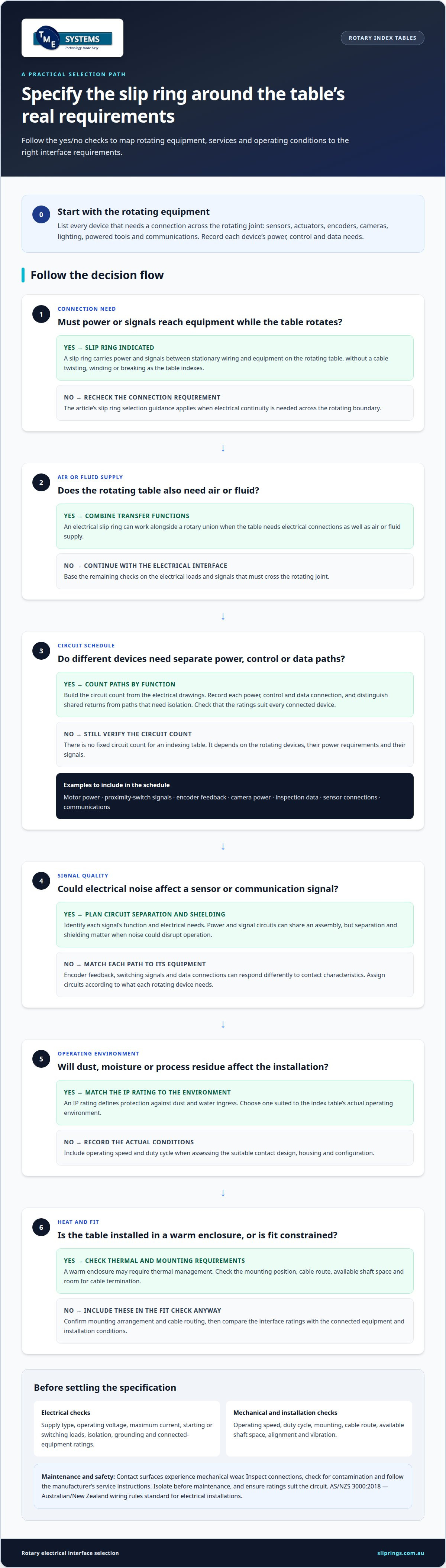
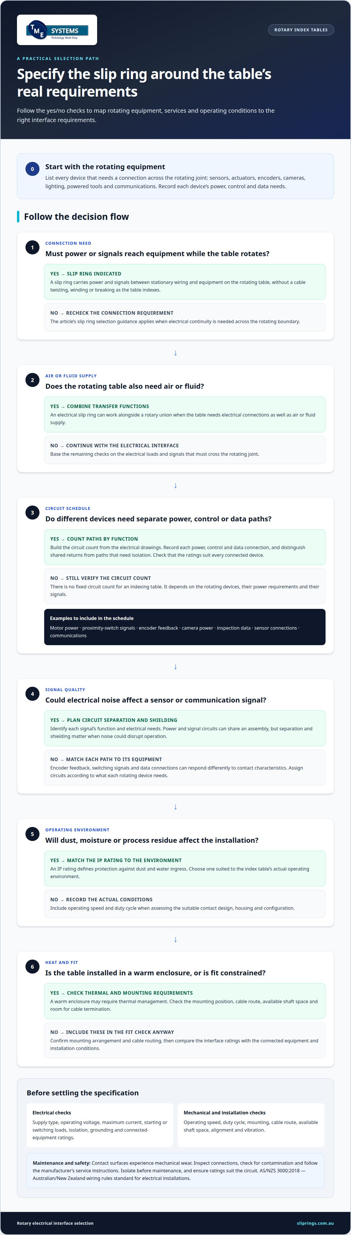
Each ring forms an independent circuit. One path might supply a table-mounted sensor, while another carries a control signal to the machine controller. Power and signal circuits can share an assembly, but the circuit count and electrical ratings must suit the connected equipment. Separation and shielding also matter when electrical noise could disrupt a sensor or communication signal.
A contact stays physically connected to its corresponding conductive track during operation. Fixed wiring feeds one side, and cables from the rotating equipment connect to the other. This lets a camera, sensor or powered tool stay connected as the table moves between stations. A rotary electrical interface for an index table is useful when fixed cables would twist or restrict movement.
Slip rings, rotary transformers and wireless rotary interfaces transfer energy in different ways. A slip ring uses conductive contacts, while a rotary transformer transfers power through magnetic coupling without direct electrical contact. A wireless interface transfers power or data without a physical contact path, using a compatible transmitter and receiver.
Rotating contact surfaces experience mechanical wear, so maintenance includes inspecting connections, checking for contamination and following the manufacturer’s service instructions. Electrical safety depends on correct installation, isolation before maintenance and ratings suited to the circuit. AS/NZS 3000:2018 - Australian/New Zealand wiring rules standard for electrical installations. An IP rating defines protection against dust and water ingress; match it to the index table’s actual environment.
Begin selection with the table’s movement and connected loads. A servo-driven index table may need separate circuits for motor power, sensors and control signals. A pneumatic table may also need an air supply, requiring a separate rotary transfer arrangement. The mounting position, cable route and available shaft space determine how the assembly fits the machine.
Signal quality depends on the application. Encoder feedback, switching signals and data connections can respond differently to electrical noise and contact characteristics. Identify what each rotating device needs, then assign circuits accordingly. For example, a vision inspection station may need power for its camera and a signal path for inspection data. Matching each path to its function helps the interface support reliable machine operation.
Slip ring selection criteria
Start with the loads and signals that must cross the rotating joint. Match the electrical, mechanical and environmental requirements to the index table’s duty.
Electrical ratings and circuit needs
Electrical ratings describe the voltage, current and signal performance a rotary interface can support. An unsuitable rating can interrupt operation or overheat components. Record the supply type, operating voltage and maximum current for every connected device. Where relevant, include starting or switching loads rather than sizing only for typical operation.
List power circuits separately from sensitive control or data circuits. A servo-driven table, for example, may carry motor power, proximity-switch signals and encoder feedback. Each path has different electrical demands. Check that the interface supports the required signal types while maintaining signal integrity alongside power transfer.
Next, consider operating conditions. A table running in a warm enclosure may need thermal management, while dust, moisture or process residue can affect the installation. Match the IP rating to the environment, and account for operating speed and duty cycle. These details help determine the suitable contact design, housing and configuration.
Assess voltage isolation between circuits, grounding arrangements and space for cable termination. These factors affect integration with the machine’s wiring and control system. Compare the interface’s ratings with the connected equipment and installation conditions, not just the table’s nominal supply.
Circuit count for indexing tables
The required circuit count is the number of independent electrical paths needed for all equipment on the rotating table. Determine it by listing each power, control and data connection that must cross the rotating joint. A camera and its lighting, for example, may need separate paths if their supply and signals differ.
Count circuits by function, then distinguish connections that share a common return from those needing isolated paths. Include spare capacity only when the machine design has a defined future requirement. This avoids an undersized assembly and unnecessary circuits that complicate wiring or mounting.
How many circuits does an indexing table need? There is no fixed count. It depends on the number and type of rotating devices, their power requirements and their signals. Build a circuit schedule from the table’s electrical drawings, including sensors, actuators, encoders and communications.
Common causes of failure include contact wear, contamination, incorrect electrical loading, poor alignment and vibration. Reduce the risk by matching ratings to actual loads, securing the mounting, protecting the assembly from its environment and following the manufacturer’s inspection and maintenance instructions. Changes to tooling or sensors can alter circuit needs, so update the schedule when the table configuration changes.
Three-phase power capability
A three-phase slip ring transfers power from fixed wiring to equipment rotating with the index table. It provides separate conductive paths for the three phase conductors, maintaining their connections during rotation. This can suit a table carrying a three-phase motor or other equipment designed for a three-phase supply.
Start with the equipment’s electrical requirements. Identify its supply arrangement, operating voltage, current demand and connection diagram. A three-phase motor’s nameplate and wiring documentation provide the basis for matching the interface. The slip ring’s ratings must suit the motor and its operating conditions, rather than simply matching the supply label.
Consider current demand throughout operation, not only at steady state. A motor can draw more current during acceleration than while running steadily. Select the interface with the motor’s starting method and load in mind, as well as its normal duty. A heavily loaded table may place different demands on the electrical path than a lightly loaded one.
Keep phase connections in the intended order. Three-phase motors can change direction if their phase sequence changes, so the rotating-side wiring must preserve the machine’s designed connections. For example, a table motor that must index in a defined direction needs consistent phase paths from the fixed supply to the rotating motor.
Other conductors may also be needed. Depending on the electrical design, the rotating assembly may require a neutral, protective earth connection or separate control circuits. These are not interchangeable with phase paths. The wiring diagram determines which conductors cross the rotary interface and how they connect to table-mounted equipment.
Consider the full electrical load when several devices rotate together. A table might carry a three-phase drive, proximity sensors and a control connection. The motor supply and lower-power signals serve different purposes and have different electrical characteristics. Assigning the required paths clearly helps prevent a circuit-count or rating mismatch.
Physical integration also affects the choice. The slip ring must fit the index table’s mounting arrangement, shaft space and cable route. A through-bore design may suit an assembly built around a central shaft, while an end-mounted unit may fit a different layout. The configuration must leave practical access for wiring and inspection.
Heat and operating conditions also affect suitability. Current flowing through electrical contacts produces heat, so ambient temperature, duty cycle and enclosure conditions matter. Dust or moisture around a packaging or machining table can affect the required protection. Match the IP rating and thermal limits to the actual installation, not an assumed factory environment.
Finally, review the interface and machine wiring together. Confirm that the supply, motor, protective conductors and controls align with the design documentation and applicable installation requirements. For Australian electrical installations, follow AS/NZS 3000:2018 - Australian/New Zealand wiring rules standard for electrical installations. A coordinated review helps resolve connection and mounting issues before commissioning.
Use of slip rings on rotary index tables
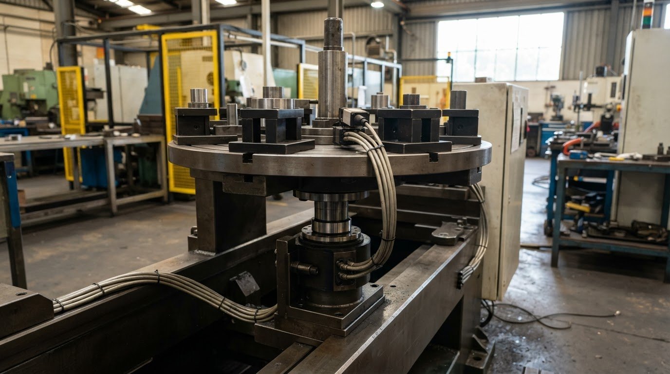
A rotary index table moves workpieces between fixed stations, so equipment on its rotating surface may need power or communications throughout the cycle. Tables with more than two stations need provision for air, electrical power, communications or a combination of these. A slip ring carries electrical connections across the rotating joint without trailing cables restricting table movement.
At an assembly station, rotating tooling may need power while sensors report position or process status. In a packaging line, a table can present containers for filling, capping, labelling and packaging. Electrical circuits support devices mounted on the rotating assembly, while stationary control equipment coordinates the sequence at each station.
Rotary index tables also support machining and inspection. A workpiece can rotate between drilling, milling or grinding operations, or be presented to inspection equipment and testing stations for quality control. A camera or sensor mounted on the table—such as the robust smart sensors documented on contrinex.com—needs an electrical connection as its position changes. The slip ring carries those signals across the rotating interface during indexing.
Air and fluid requirements need separate consideration. A rotary union can work with an electrical slip ring to transfer compressed air or fluids to rotating tooling and fixtures. For example, while mechanical fixtures often utilise horizontal toggle clamps to secure parts without extra lines, a pneumatic clamp on the rotating table may need air while sensors need electrical connections. The combined arrangement must fit the table layout and keep each transfer path suited to its function.
How do you install and wire a slip ring on an indexing table? Mount its stationary part to the fixed machine structure and its rotating part to the table, following the assembly drawing. Connect each conductor according to the slip ring wiring diagram and machine circuit schedule, assigning power, signal and protective connections correctly.
The mounting arrangement depends on the indexer’s shaft, available space and cable route. A through-bore slip ring can fit around a central shaft, while an end-mounted design may suit a table with accessible shaft-end space. Secure the rotating cable to the table so it does not obstruct fixtures, tooling or movement.
Plan integration around the table’s full operating cycle, not just one station. Check whether rotating equipment needs power continuously, only during a process, or communication throughout indexing. For example, an inspection camera may need a stable data path as the table advances between stations. Account for conditions such as machining debris or moisture in packaging areas when determining enclosure protection.
Before commissioning, compare the installed connections with the equipment drawings and run the table through its intended operating sequence. Check that cables remain clear during rotation and connected devices function at each station. If the table combines electrical circuits with pneumatic tooling, verify that the slip ring and rotary union interfaces suit the machine layout and operating requirements.
What electrical ratings and circuits should a rotary interface support?
Match the interface to every load and signal crossing the rotating joint. A table carrying a motor, encoder and sensors needs different circuit functions, not just enough conductors to complete the installation.
Start with the equipment schedule and record each device’s supply type, voltage, current and connection requirements. Use the motor nameplate and control-system drawings to identify them. For example, a three-phase drive, proximity sensor and encoder each have distinct connection needs. The interface must support each circuit’s electrical demands under the table’s actual operating conditions.
Current capacity must reflect how each load operates. A motor may draw a different current during acceleration than during steady operation, while an actuator may switch on only at a particular station. Assess the operating sequence and simultaneous loads rather than adding ratings without considering when equipment runs. Ambient temperature and duty cycle also affect heat generated at contacts.
Voltage rating is not the only insulation consideration. Review the required separation between power conductors and low-level signals, along with circuit isolation and protective-earth arrangements. For example, encoder feedback can be vulnerable to interference from nearby motor circuits. Appropriate circuit allocation and wiring practices help maintain signal quality without treating all paths as interchangeable.
Set the circuit count using a connection schedule. List each independent power, control, feedback and data path between the stationary machine and rotating equipment. A sensor’s supply and output may need separate conductors, and an encoder may have multiple signal connections. Follow the device wiring diagrams, accounting for returns and protective connections as the electrical design requires.
Review signal requirements separately. Switching signals, analogue outputs, encoder feedback and Ethernet data have different transmission characteristics. Check that the rotary interface suits the signal type and intended data performance. If the table carries a vision system, include both camera power and its data connection rather than counting the camera as one generic circuit.
Then assess thermal derating, the reduction in allowable current as ambient temperature rises. Heat from adjacent equipment, a confined enclosure or sustained operation can affect the current a circuit can carry. Consider the interface’s thermal limits together with the installation environment; a rating in isolation does not describe every operating condition.
Mechanical ratings matter too. Confirm that the rotational speed rating suits the table’s motion, including its indexing and dwell pattern. Check mounting, shaft clearance and cable routing against the machine drawings. A compact end-mounted unit and a through-bore arrangement fit differently, so use the table geometry to guide the form factor.
Finally, compare the connection schedule with the interface documentation and machine wiring before commissioning. For Australian installations, follow AS/NZS 3000:2018 - Australian/New Zealand wiring rules standard for electrical installations. Technical application consulting can help evaluate circuit count, ratings, signal needs and mounting together.
TME Systems: Mercotac Slip Rings
TME Systems supplies Mercotac Slip Rings for transferring electricity between stationary and rotating equipment. For an index table, the right choice depends on the circuits, electrical loads, movement, mounting arrangement and operating environment identified in the machine design.
For applications better suited to another product range, TME Systems also supplies Meridian Laboratory Slip Rings, BGB Innovation Slip Rings and Prosper Rotation Slip Rings. Comparing the table’s requirements with these options helps narrow the selection without treating every rotating application alike.
Discuss your rotary interface requirements with TME Systems at sliprings.com.au.
Plan the interface around the machine design
Before finalising an index table, capture its electrical and mechanical requirements in one design brief. Include the circuit schedule, equipment connection diagrams, mounting space, cable routes and operating environment. This defines the rotary electrical interface for an index table as part of the wider machine, rather than leaving integration details until assembly.
Consider future changes during design, too. A new sensor, tool or inspection device can affect circuit allocation and routing. Clear drawings help the engineering team understand how the rotating assembly connects to stationary controls and fits the table layout.
If you’re developing a new table or reviewing an existing design, TME Systems’ technical application consulting can help assess the requirements and suitable slip ring options. Contact TME Systems to discuss your application and take the next step towards a well-matched rotary connection.
Frequently Asked Questions
Why are slip rings used on rotary index tables?
Slip rings keep equipment mounted on a table electrically connected as it moves between work positions. This helps when a sensor, clamp or inspection device on the rotating section needs wiring. Without a rotary connection, fixed cables can twist or restrict movement. For example, a sensor can report a workpiece’s position as the table advances to the next operation.
What is a slip ring used for?
A slip ring carries electrical power, control signals or data across a rotating connection. Industrial uses include powering a rotating tool, connecting a sensor or carrying camera data from a moving inspection head. The circuit arrangement depends on the equipment: a powered device and its feedback signal may need separate paths. Air or fluid transfer is a separate function handled by a rotary union.
What is a rotary electrical interface for an indexing table?
A rotary electrical interface for an indexing table is the connection assembly between stationary machine wiring and electrical equipment on the rotating table. Its stationary side connects to fixed wiring, and its rotating side connects to table-mounted devices. The assembly is part of the machine’s electrical design, alongside the control system, wiring schedule and equipment connections. A slip ring is one type of interface.
How do slip rings transfer power and signals to a rotating index table?
Conductive tracks and contacts maintain electrical paths between the fixed and rotating sides as the table moves. Each assigned path connects a machine circuit to a device on the table. For example, a controller can send a command to a rotating actuator while receiving a sensor signal. Signal and data circuits need a suitable configuration, particularly where nearby power circuits could affect communication.
How to select a rotary interface for speed, torque, and duty cycle?
Match the interface’s rotational speed rating and electrical duty to the table’s operating profile. Record how often it rotates, how long connected equipment operates, and which loads run together. Torque is primarily a mechanical requirement for the indexer and its drive, not an electrical rating for the slip ring. Check that the mounting arrangement fits the rotating assembly without interfering with the drive or cabling.