Could a dropout that appears only while equipment rotates be caused by heat or power rather than the signal path itself? Yes. Rising temperature, voltage dips, loose or damaged connections, and electrical interference can all disrupt signal continuity. Troubleshooting intermittent signal loss during rotation starts by recording when the fault occurs and checking power and connections under operating conditions, rather than replacing components at random.
A suspected loose connection or failing component is a useful starting point, but a fault that follows rotation can have several causes. A systematic check helps distinguish a heat or supply problem from wiring, interference, or maintenance issues.
This guide explains how to inspect connections, monitor supply voltage and temperature, check for interference, and use fault timing and diagnostic records to narrow down the cause. It also shows how to assess whether the signal path, sensor, or rotary electrical joint needs closer attention.
Key Takeaways
- Track when dropouts occur and compare supply voltage during normal operation and signal loss to help identify heat or power-related faults.
- Inspect wiring, terminals and connector contacts for looseness, wear or corrosion, especially where movement may disturb a connection.
- Change one variable at a time, using channel swaps or a known-good sensor to narrow down the source of the fault.
- Check whether nearby electrical equipment or a changing rotation angle corresponds with signal disruption, and use diagnostic records to identify patterns.
- When the fault points to the rotary electrical joint, technical application consulting can help match a Prosper Rotation slip ring to the application’s circuit, electrical and mounting requirements.
Intermittent signal loss and loose connections
Loose terminals, damaged cables, and worn rotary contacts can interrupt signals as equipment turns. Follow these steps to distinguish connection faults from failures linked to rotation position.
-
Gather diagnostic tools
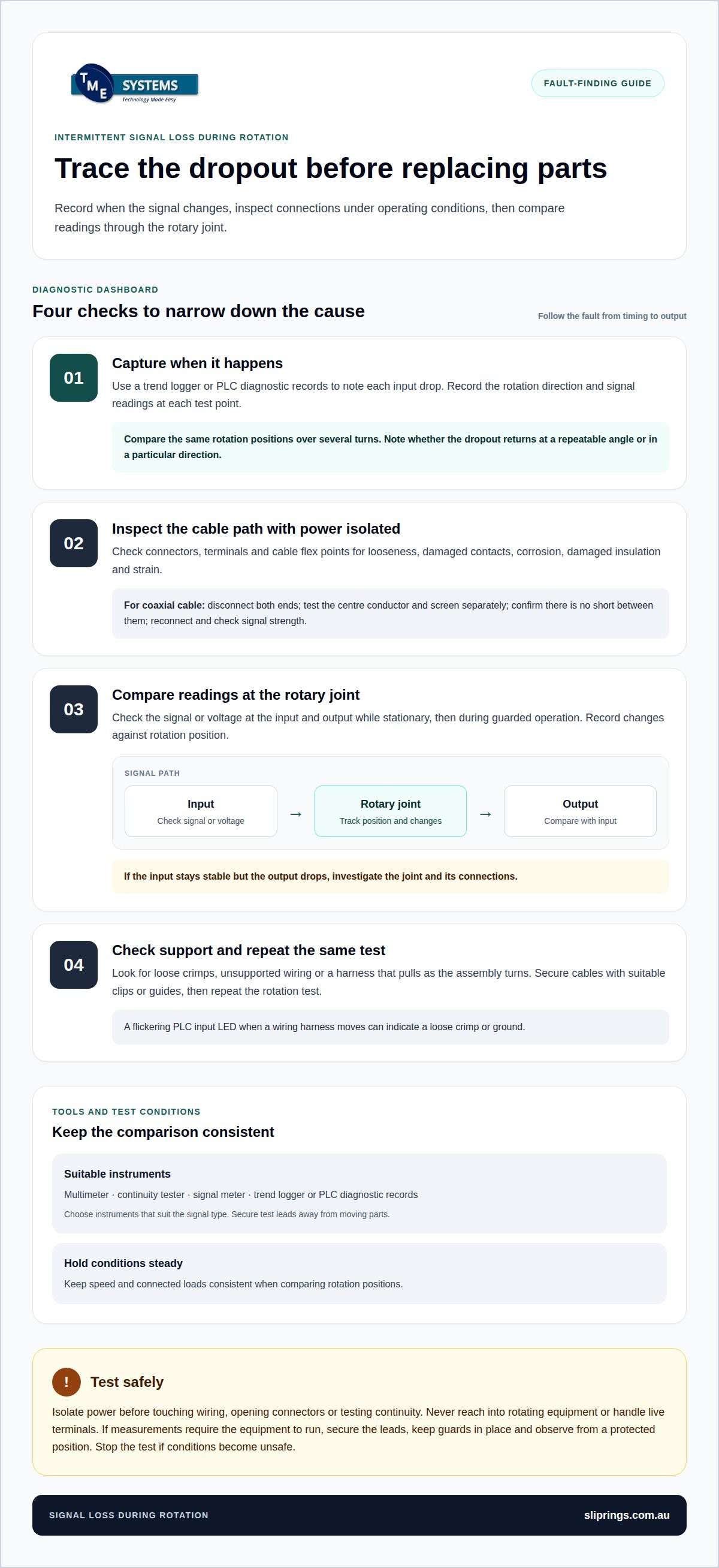
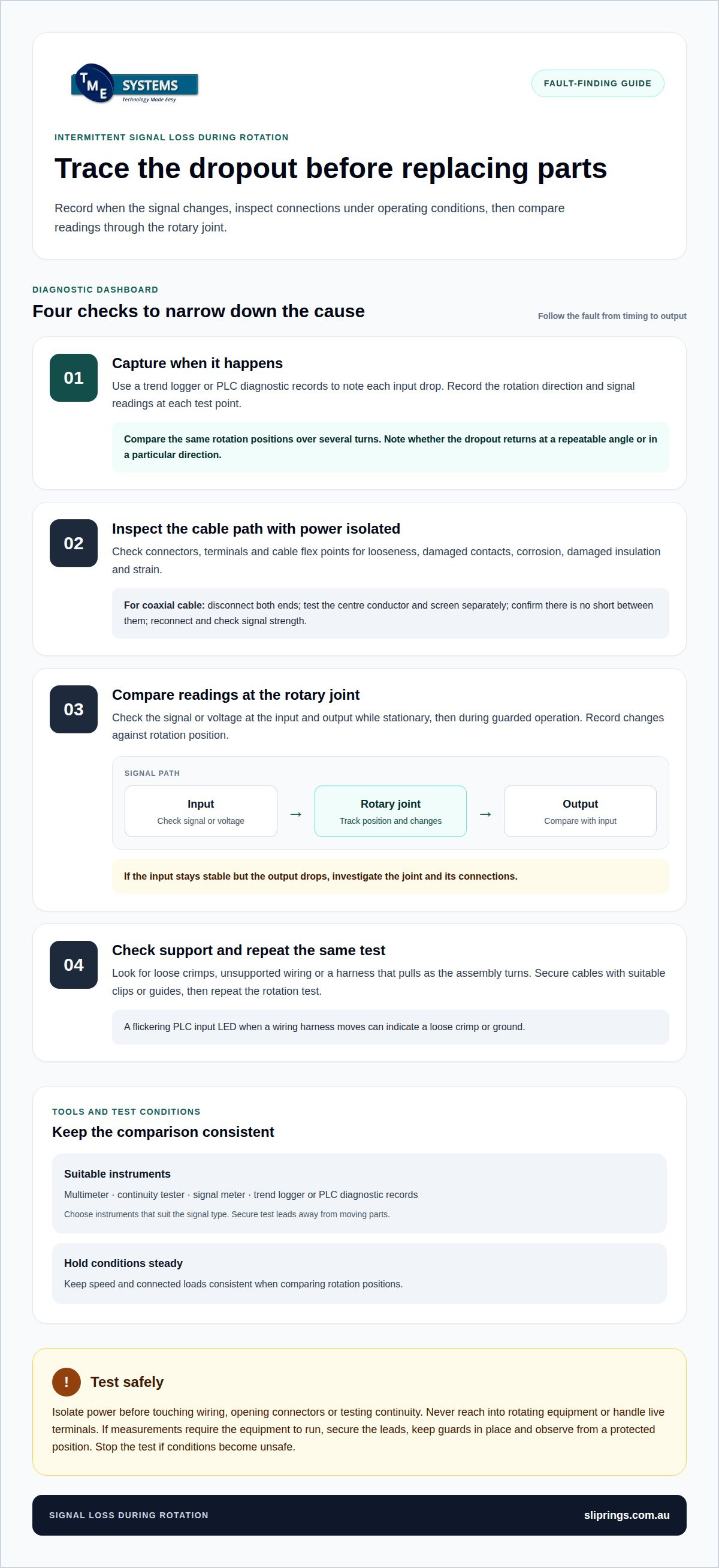
Prepare a multimeter, continuity tester, and signal meter suited to the circuit. Use a trend logger or PLC diagnostic records to note when the input drops. Record the rotation direction and signal readings at each test point. Choose instruments compatible with the signal type, and secure test leads away from moving parts.
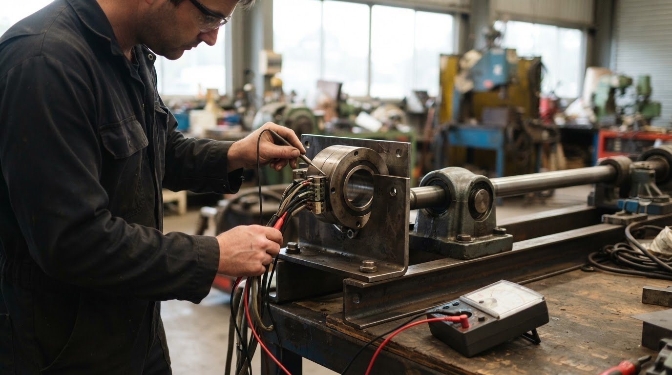
- With power isolated, inspect and test the cable path. Check each connector for looseness, damaged contacts, corrosion, and strain where the cable flexes. For coaxial cable, disconnect both ends and use a continuity tester to check the centre conductor and screen separately. Confirm there is no short between them, then reconnect and check signal strength with a meter.
-
Check for angle-specific signal loss
Record the rotation position whenever the PLC input or signal meter changes. Compare readings at the same positions over several turns, noting whether the dropout returns at a repeatable angle or in a particular direction. Keep speed and connected loads consistent during comparisons. A repeatable pattern can point to a cable bend, connector movement, or rotary contact affected by rotation.
-
Test the rotary joint or slip ring
A faulty rotary joint or slip ring can interrupt electrical continuity as its contacts move, causing signal loss during rotation. Compare the signal or voltage at its input and output while stationary, then during guarded operation with secured instruments. Record changes against rotation position. If the input stays stable but the output drops, investigate the joint and its connections.
- Check terminals and cable support before replacing components. With power isolated, look for loose crimps, damaged insulation, corrosion, and unsupported wiring that could pull as the assembly turns. A flickering PLC input LED when a wiring harness moves can indicate a loose crimp or ground. Secure cables with suitable clips or guides, then repeat the same rotation test.
- Keep clear of moving machinery and exposed electrical connections during inspection. Isolate power before touching wiring, opening connectors, or testing continuity. Never reach into rotating equipment or handle live terminals. If measurements require the equipment to run, secure the leads and observe from a protected position with guards in place. Stop the test if conditions become unsafe.
For intermittent PLC input loss, checking wiring continuity and inspecting terminals for looseness can help isolate the fault. Look for loose contacts, damage, and corrosion as part of the inspection. Compare signal readings during rotation to help distinguish a connection problem from a fault linked to equipment position.
For a satellite no-signal problem, check cable connections and tighten them as a basic troubleshooting step. On antenna setups subject to frequent motion or vibration, support wiring with clips or guides, and periodically check that mounts are tight. Receiver error 535 can indicate a system communication fault related to a switch or wiring issue.
Changing one variable at a time
A controlled substitution can show whether a fault lies with an input channel, sensor, or signal format. Change one element per trial and leave the rest of the test setup unchanged.
- Define the test conditions before starting. Use the same machine program, sensor target, and operating sequence for each trial. Record which component is under test and whether the input registers correctly. This creates a clear pass-or-fail comparison without mixing results from different setups.
- Swap the suspect PLC input channel with one carrying a known-good signal. Keep the original sensor and its connections in place. If the fault follows the input channel, focus on its configuration or hardware. If the fault stays with the original sensor signal, the channel swap has helped narrow down the cause.
- Substitute a known-good sensor of the same suitable type. Keep the PLC channel and program unchanged, and position the replacement to detect the same target. If the input behaves correctly with the substitute, the original sensor becomes a stronger suspect. If both sensors behave alike, test another element on its own.
- Use the PLC input indicator to compare each substitution. Observe whether the indicator changes state as expected during the test sequence. A digital camcorder recording of the input LED, reviewed slowly, can reveal brief dimming that is easy to miss in real time. Keep the camera outside moving machinery.
- For video or display signals, hold the source and display constant while testing a different cable or signal mode separately. A cable that works at 1080p and 60 Hz may still be unreliable at 1440p and 165 Hz. If changing the mode restores a stable image, the signal path’s bandwidth may be a factor, rather than the rotating mechanism.
- Restore the original configuration after each trial unless the test requires otherwise. Clearly mark each substituted part and setting to avoid confusing results between trials. Do not change a sensor, input channel, and program setting together. Even if the fault disappears, changing them all at once will not reveal which variable mattered.
- Use the test results to define the next selection criteria, rather than replacing parts by guesswork. For a rotary electrical connection, match circuit count, current, voltage, speed and mounting style to the application. Prosper Rotation slip ring options can be considered when those requirements identify the rotary connection as the component to specify. This approach keeps troubleshooting intermittent signal loss during rotation focused on evidence from each controlled trial.
Electrical interference
Electrical noise can disrupt sensor inputs even when cables and connectors look intact. Compare signal behaviour under different nearby equipment and operating conditions before changing settings.
- Monitor the sensor supply line under load while the signal is stable, then during a dropout. Record voltage changes and visible noise at the PLC input. A dip or disturbance coinciding with the failure points towards the supply or electrical environment. Repeat under the same operating conditions to avoid confusing load changes with interference.
- Identify nearby equipment that switches or generates electrical activity. Motors, wireless repeaters, and radar equipment can interfere with antenna signals. Note when each device operates and compare its timing with the dropout. If the fault coincides with a device switching on, test that influence in a controlled way rather than changing several settings.
- Separate signal wiring from power cables where the installation allows. Check for long parallel cable runs beside motor supplies, switching equipment, or other likely noise sources. See whether temporarily repositioning a signal cable changes the reading, while keeping rotation and load consistent. Restore the original route after the comparison.
- Check the full antenna path when the rotating system uses satellite or radio telemetry. Buildings, metal roofs, and reflective surfaces can distort signals or block the line of sight to the intended satellite or relay point. Compare reception at different system positions and note whether movement puts an obstruction between the antenna and its target.
- Compare dropouts with weather and other external conditions. Rain, snow, and lightning can affect signal travel in antenna telemetry systems. For Australian television reception, atmospheric ducting can bring distant services into interference with local services, particularly in warmer months and early evening. A weather-linked fault may behave differently from one that recurs at the same rotation angle.
- Check for mobile network overload if the system uses nearby television reception equipment. In Australia, a mobile phone tower may affect reception, especially within 1 km when a signal amplifier is in use. A local antenna installer may address overload by fitting a 4G filter, removing a booster or moving the antenna. Avoid adding amplification without assessing the cause.
- Change one interference condition at a time, then record the signal level and PLC input response. If moving a cable, isolating a device, or changing antenna direction alters reception, repeat the check to confirm the pattern. Document the original settings so each adjustment can be reversed and the likely source remains traceable.
How to determine whether rotation-related signal loss is caused by a cable, connector, or rotary electrical joint?
Trace the signal path in order, from the industrial sensor through cables and connectors to the rotary electrical joint and receiving equipment. Change one component at a time and record where readings become unstable.
- Start by inspecting the cable route from the sensor to the equipment input. Look for crushed insulation, sharp bends, abrasion, strain, or contact with the rotating structure. A cable can look intact yet fail internally, so compare signal behaviour while stationary and during normal rotation. Note any change at a repeatable position.
- Check each connector for looseness, wear, corrosion, and damaged contacts. Inspect connectors at both ends of the cable, then check ports for bent pins or contact damage. Moisture or corrosion on industrial connectors can weaken the signal and cause intermittent loss. Record the connector location if moving it changes the signal.
- Test the cable independently where the system design allows. Disconnect it at both ends, test continuity, and check for unwanted contact between conductors. Reconnect the cable and compare signal readings over the same rotation path. Replace a suspect cable promptly, even if the exterior looks undamaged.
- Check whether the sensor is securely mounted and operating as intended. Inspect its mounting and connections, then compare sensor readings at the same rotation positions. If the signal changes as the equipment turns but cable readings stay stable, investigate sensor movement, obstruction, or a change in the sensor’s operating conditions.
- Separate the fixed cable path from the rotary interface. Measure the signal before and after the slip ring or rotary electrical joint using suitable test points and consistent operating conditions. If the input stays stable while the output drops during rotation, the fault is more likely within the joint or its immediate connections. If both readings fall, trace the signal upstream.
- Compare the results with the fault’s movement pattern. A dropout at a particular cable position suggests flexing or internal damage. A change when touching one connector points towards its contact or termination. Repeatable output loss across the rotary electrical joint, while its input stays steady, narrows the investigation to that interface.
- Record readings, rotation position, and the component tested before replacing parts. Avoid changing the sensor, cable, and rotary electrical joint together, as this hides the source. Testing in sequence helps distinguish a faulty cable or connector from sensor operation and slip-ring continuity problems.
What diagnostic steps can identify signal loss that occurs only at certain rotation angles?
If the fault recurs at a particular angle, investigate the equipment’s geometry and intended movement path. Use position references and application records to distinguish an alignment issue from a fault in the rotary electrical connection.
- Define the machine’s position reference, such as its home mark or axis coordinate. Confirm that the reference matches the equipment’s actual orientation. A position value is useful only when its zero point and direction are understood, particularly after installation work or a mechanical adjustment.
- Compare reported axis positions with the actual coordinates the equipment should reach. Check the intended movement path where the signal becomes unreliable. A mismatch between the reported position and required position can indicate a recalibration issue rather than a failed signal component.
- Assess each axis separately. If the fault appears during horizontal movement, examine that axis; if it appears during vertical adjustment, examine the vertical axis. This helps identify which axis or movement is associated with the change.
- Monitor the signal while moving the equipment through the relevant part of its travel. Observe signal strength and quality as it changes position, rather than relying only on the control-system display after movement stops. Note whether the reading changes during movement or remains poor once the equipment reaches its intended position.
- Check whether cables, connectors or the rotary electrical connection are affected at a particular orientation. A change in cable routing or contact at only one angle can cause a position-specific signal problem. Assess the connection throughout the equipment’s actual movement, not just in its parked position.
- After recalibration, compare the observed equipment position with its movement requirement. If the reported axis position and physical orientation disagree, correct the position reference before assessing signal hardware. If they align but the signal changes during movement, keep the readings and movement details for the next diagnostic review.
- Tie the results to the relevant axis and physical orientation. Distinguish a reading that falls during movement from one that stays low at the final position. This helps separate a tracking or alignment discrepancy from a persistent fault in the rotary electrical connection and gives the next assessment a defined condition to investigate.
For control-system checks, PLC diagnostic logs can help identify when an input signal drops. Move the wiring harness while watching the input LED to help reveal intermittent wiring faults. Check encoder updates in real time to confirm equipment positioning feedback is accurate. Relating these observations to movement can show whether feedback changes when signal loss occurs.
A trend logger can help assess whether intermittent PLC input signal loss is associated with hardware or a sensor. In industrial equipment maintenance, log error messages and look for patterns. Monitor signal strength and quality while moving the equipment. Compare these readings with the control-system record to associate each signal change with its position and movement.
TME Systems: Prosper Rotation Slip Rings
If signal loss persists after cable, connector, and power checks, TME Systems Pty Ltd can help assess whether a rotary electrical joint suits the application. Its technical application consulting considers circuit count, current, voltage, speed, mounting style, and environmental requirements to guide slip-ring selection.
Prosper Rotation Slip Rings are one option to consider alongside Mercotac, Meridian Laboratory and BGB Innovation slip rings. Share the recorded fault conditions and system requirements so the selection can be based on the rotation and electrical demands involved. This step is most relevant when diagnostics point to the rotary interface, or when specifying a replacement or new assembly.
Contact TME Systems Pty Ltd to discuss your slip ring application and diagnostic findings.
Turn diagnostic findings into a clearer next step
Keep the fault record for future commissioning and maintenance. Store the test conditions, equipment configuration, and observed signal behaviour together so later changes can be compared against the same baseline. This gives the engineering team a practical record and helps distinguish a new fault from a familiar operating pattern.
If troubleshooting intermittent signal loss during rotation points to the rotary electrical joint, assess whether the slip ring suits the application’s electrical and mechanical requirements. Circuit count, current, voltage, speed, mounting style, and operating environment all inform that decision. TME Systems offers technical application consulting to help match those requirements to a suitable slip-ring option.
Share the recorded symptoms and application requirements to move from diagnosis towards component selection. Contact TME Systems to discuss the next step for your rotating equipment.
Frequently Asked Questions
Could Heat or Power Issues Be Causing Dropouts?
Yes. A fault that appears only after equipment has run for a while may be heat-related, while one that coincides with a heavier operating load may involve power delivery. Compare behaviour after a cold start with behaviour once the machinery has warmed. Note whether the fault follows operating time or a particular movement, as these patterns can point to different causes.
What causes intermittent signal loss during rotation?
The pattern across channels can distinguish a local fault from a shared one. If several signals drop together, investigate components common to those paths, such as a shared supply or receiver. If one signal is affected while others stay stable, focus on that channel’s sensor and route. A signal that returns without intervention may indicate a temporary disturbance rather than permanent component failure.
How should connectors and cables be inspected and repaired to prevent signal loss during rotation?
After identifying damage, replace the affected cable or terminal with a compatible part and preserve the original wiring arrangement. When sourcing replacement cabling, connectors, or general hardware, retailers such as Asthome Smart Electrical Supplies offer a wide range of reliable electrical components. For shielded cables, maintain shield continuity through the termination and restore cable support so the connector does not carry movement-related strain. Follow the equipment and connector manufacturer’s termination instructions. After repair, document the parts changed and confirm the equipment operates correctly through its intended movement cycle.