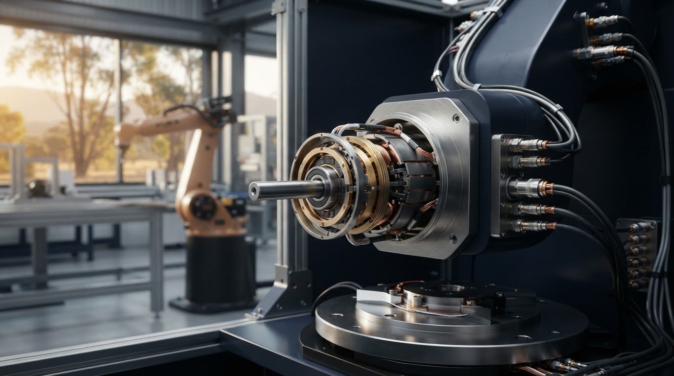
An industrial electrical swivel connector maintains power and signal connections while equipment rotates through 360 degrees. The suitable type depends on the application’s electrical load, signal requirements, rotation speed, mounting arrangement and operating environment.
Choosing an industrial electrical swivel connector involves more than matching a connector to a rotating shaft. Brush-type slip rings, mercury-wetted rotary connectors and other rotary electrical joints work differently, and speed and contact design affect service life.
This guide explains what rotary electrical connectors do, how connector type and grade relate to speed and service life, and which configurations suit industrial equipment. It also covers practical selection factors, including circuit count, current, voltage, mounting options and environmental conditions, so you can narrow the choice to the demands of your application.
Key Takeaways
- Match voltage, current, circuit count and signal needs to the connector’s electrical design before selecting a type.
- Compare contact technology and rotational speed rating to understand how operating conditions can affect working life.
- Map the connector to the equipment’s movement and duty, then choose a mounting arrangement that fits the mechanical layout.
- Use the Australian conditions and standards section to identify the environmental and compliance factors relevant to your application.
- Bring your application requirements together to narrow the options, including slip rings from Mercotac, Meridian Laboratory, BGB Innovation and Prosper Rotation.
What Is A Rotary Electrical Connector?
A rotary electrical connector maintains electrical paths between stationary and rotating parts. To select an industrial electrical swivel connector, start with the load, signal types and installation conditions.
Voltage, Current and Signal Requirements
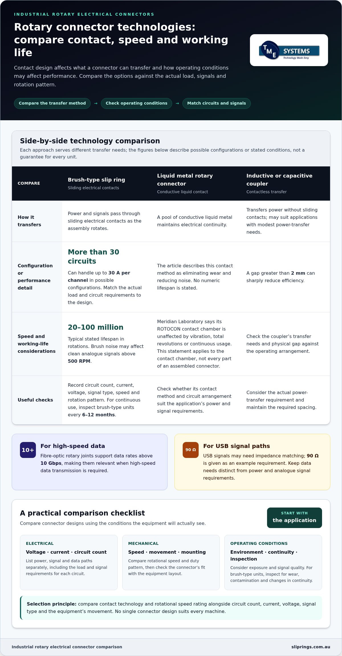
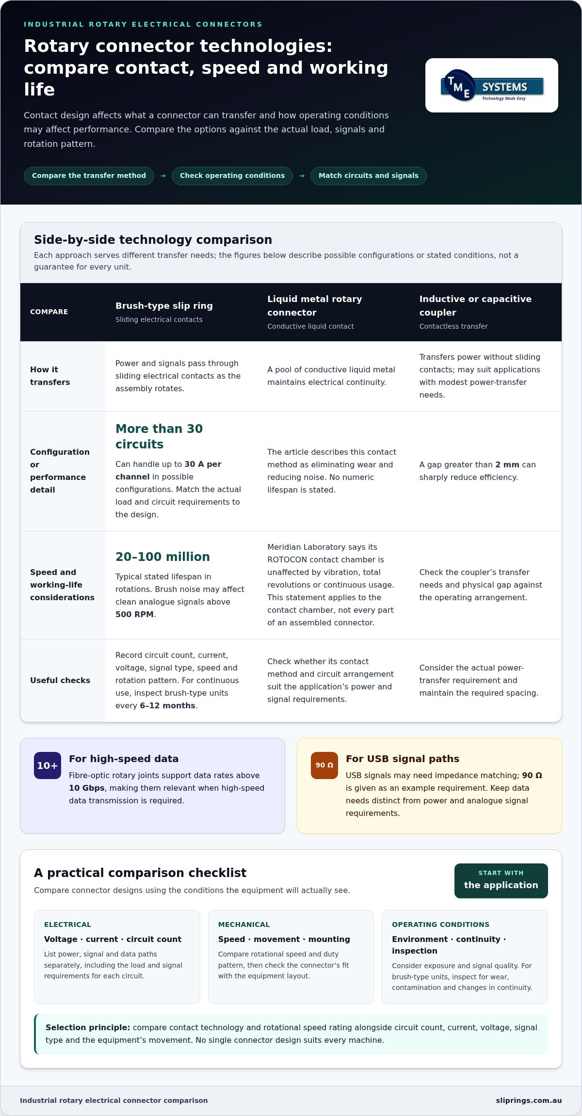
Start with the equipment’s voltage and current requirements for each circuit. Brush-type slip rings can support more than 30 circuits and handle up to 30 A per channel. These figures describe possible configurations, not a substitute for matching a unit to the actual load. Record each circuit’s operating voltage, current and duty before comparing designs.
Separate power circuits from low-level signals. A motor supply and a thermocouple signal have different transmission needs, even when they share one connector. For thermocouple circuits, consider the signal path and compatible connections. Include signal type, circuit count and measurement requirements in the specification, rather than describing every path simply as electrical wiring.
For safe installation, isolate the equipment and follow the connector manufacturer’s wiring and mounting instructions. Match each terminal to the wiring diagram, then check the connections before returning the assembly to service.
Power, Signal and Data Transfer
Contact slip rings transfer power and signals through sliding electrical contacts as the assembly rotates. Brush-type units can suit applications that need multiple circuits, but the arrangement must accommodate each circuit’s load and signal characteristics. For example, power and thermocouple paths may need separate circuits to keep their functions distinct.
Contactless inductive or capacitive couplers may be suitable where power-transfer needs are modest. A gap greater than 2 mm can sharply reduce their efficiency. Fibre-optic rotary joints support data rates above 10 Gbps, making them relevant when high-speed data transmission is required. USB signals, by contrast, may need impedance matching, with 90 Ω given as an example requirement.
Keep power, analogue signals and data requirements distinct in the design. This helps ensure the selected connector’s circuit arrangement meets each transmission need instead of treating all connections alike.
Australian Ratings and Standards
For Australian installations, distinguish a connector’s component ratings from the rules that apply to electrical installations. AS/NZS 3000:2018 is the Australian/New Zealand wiring rules standard for electrical installations. Its relevance is installation-related; it does not, by itself, describe every performance characteristic of a rotary connector.
Assess the connector’s voltage and current ratings alongside the equipment’s operating conditions. The IP rating defines protection against dust and water ingress, so consider the actual exposure around the rotating assembly. AS/NZS 5368:2025 is another identifier to include when it appears in the project requirements. Confirm that the specification addresses the connector’s intended use and installation context.
Common failure risks include incorrect wiring, unsuitable loading, contamination and contact wear. If a circuit fails, isolate the equipment, compare the wiring with the diagram, then inspect the connector for visible damage or contamination.
Product grade, rotation speed and working life
Working life depends on contact design, operating speed and how the machine cycles. Compare continuous rotation with limited movement, such as an application that turns less than ±180° infrequently.
Product Grade and Working Life
Product grade matters through the design’s ability to meet the application’s duty, rather than through a label alone. Brush-type slip rings typically have a lifespan of 20 million to 100 million rotations. Treat that range as a guide to the contact type, then compare the expected rotation pattern and operating conditions with the equipment’s duty.
Brushless options use a different contact method. Liquid metal rotary connectors use a pool of conductive liquid metal to maintain electrical continuity, eliminating wear and reducing noise. Meridian Laboratory says its ROTOCON contact chamber is unaffected by vibration, total revolutions or continuous usage. That statement concerns the contact chamber, not every part of an assembled connector.
For maintenance, inspect brush-type units every 6-12 months when they are in continuous use. Look for wear, contamination and changes in signal or power continuity, then compare findings with the manufacturer’s maintenance guidance.
Rotation Speed and Circuit Requirements
Check the rotational speed rating against the machine’s operating speed, including its normal duty pattern. Brush noise may affect clean analogue signals when an application exceeds 500 RPM. If the connector carries measurement signals, such as sensor outputs, consider whether contact noise could affect the required signal quality at that speed.
For circuit planning, list each power, signal and data path separately. Compare the total circuit count with the connector design, and check which circuits operate together. A design carrying motor power and low-level analogue signals has different requirements from one carrying power alone, even at the same speed.
Assess speed and circuit count together. Higher speed affects contact behaviour, while additional circuits affect the assembly’s electrical layout. Record operating speed, rotation pattern, circuit types and continuity needs before comparing options. This gives the selection process a clear basis without assuming one design suits every machine.
A rotary switch or flexible flat cable may suffice when movement is limited to less than ±180° and infrequent. By contrast, an electrical swivel connector may suit equipment requiring more than 10,000 continuous cycles without maintenance. These are different duty patterns: consider the rotation range and cycle frequency before selecting a continuously rotating design.
For an application with clean analogue signals above 500 RPM, include signal quality in the assessment, not just mechanical speed. This helps distinguish a connector suitable for the rotation from one that also supports the required electrical performance.
Connector applications in industrial equipment
Rotary electrical connectors suit equipment that must exchange power or signals across a moving joint. Applications range from crane slewing systems to packaging machinery, with connector design driven by the equipment’s movement and operating duty.
On a crane, the upper structure rotates while electrical connections must cross the slewing interface. A high‑current slip ring for cranes is designed to transfer hundreds to thousands of amperes and up to 1 kV AC in crane slewing applications. The specification also needs to account for control circuits and signals used by the equipment.
In a wind turbine, rotating assemblies and stationary systems need electrical paths across their interface. Identify which connections cross the joint, such as power, control or monitoring signals. Then consider the turbine’s movement, harsh operating environment and maintenance access when comparing connector arrangements.
Packaging and processing machinery often combines rotating stations with sensors, actuators and control equipment. A rotary table, for example, may need motor power alongside signal paths for position feedback. Separating these requirements helps define the circuit arrangement and match the connector to the machine’s functions.
Robotic equipment may need connections to tools or sensors across a rotating joint. Map each joint’s movement and note where cables could twist or restrict motion. A rotary connector transfers electrical paths across the rotating interface, while the required circuit types depend on the robot’s power and control design.
Turntables and indexing equipment have a different duty pattern from continuously rotating machinery. An indexing station may rotate, pause, then move again as products pass through a process. Describe this movement sequence and identify which signals or power paths must remain connected during rotation. This distinguishes intermittent operation from continuous duty.
Before selecting a connector, list the equipment type, rotating interface, electrical paths, movement pattern and surrounding conditions. A wind turbine, water-treatment plant and packaging line may all need rotary transmission, but their loads, signals and mechanical layouts differ. This list gives engineering teams a practical basis for comparing connector types.
Consider installation space and access as well. A compact machine may constrain the connector’s position, while the rotating shaft can determine how the assembly is mounted. For a new design, include these details alongside the electrical diagram. For a replacement, document the existing connections and movement before choosing an equivalent arrangement.
Connector types and configurations
An electrical swivel connector commonly refers to a rotary electrical joint. Slip rings provide electrical paths across rotating interfaces, while cable reels wind and unwind cable to manage its movement. They do not perform the same role as a connector transferring power or signals across a rotating joint.
Contact method is one way to distinguish connector designs. Brush-type slip rings use sliding contacts and suit applications requiring multiple electrical paths. Liquid metal rotary connectors use a pool of conductive liquid metal to maintain continuity, eliminating wear and reducing noise. Contactless couplers transfer power without sliding contacts, while fibre-optic rotary joints carry optical data across rotation.
Configuration also determines how a connector fits the equipment. A through-bore slip ring has a hollow centre for shaft integration or components that need to pass through. A capsule slip ring has a compact form for end-of-shaft mounting. Choose the arrangement based on the shaft, available space, cable entry and any components that must pass through the centre.
Some designs combine different transmission functions in one assembly. Modular systems can combine functional modules to accommodate distinct power and signal needs. Circuit count is the number of independent electrical paths available. For example, a machine needing motor power, control signals and sensor connections must allocate paths to each function.
- Brush-type: A contact design for transferring power or signals through sliding electrical contacts.
- Liquid metal: A brushless contact method for maintaining electrical continuity.
- Through-bore: A hollow-centre arrangement for shaft integration or auxiliary components.
- Capsule: A compact solid unit for end-of-shaft mounting.
Standardisation can simplify selection where a standard configuration matches the application. Meridian Laboratory offers over 350 standardised ROTOCON slip ring configurations. Compare the required circuit count, mounting arrangement and transmission functions against the available configuration, rather than choosing by form factor alone.
Collector rings and slip rings are related rotary electrical components, but the right choice depends on the application’s load and signal needs. Compare the required current, circuit arrangement and transmission types with the features of the available connector designs.
To narrow the options, document the rotating interface, mounting space, required electrical paths and data needs. Then compare contact method and configuration with those requirements. This helps distinguish a connector suited to continuous rotation from a cable reel designed to manage a moving cable.
Which industrial electrical swivel connectors are rated for Australian conditions and standards?
No single rating makes a rotary connector suitable for every Australian installation. Assess its electrical ratings, environmental protection and operating conditions against the equipment’s design and installation requirements. Component ratings and installation rules address different parts of the selection.
Start with the site environment. Dust, water, humidity, temperature changes and vibration can affect connector performance. An IP rating describes protection against dust and water ingress, so compare it with actual exposure around the rotating joint. A unit inside a protected enclosure faces different conditions from one exposed to washdown or airborne dust.
Next, compare the connector’s voltage and current ratings with the equipment’s electrical load. Ambient temperature affects heat dissipation, and high current contributes to temperature rise. Consider thermal management and any reduction in allowable current as ambient temperature increases, particularly when the connector operates inside a warm enclosure or near other heat-producing equipment.
For installation context, AS/NZS 3000:2018 is the Australian/New Zealand wiring rules standard for electrical installations. It concerns electrical installation requirements, rather than establishing every operating rating for a rotary connector. The equipment design still needs to account for the connector’s stated ratings, wiring arrangement and operating conditions.
AS/NZS 5368:2025 is another identifier provided for consideration in this context. Treat it as a project requirement to assess alongside the equipment specification, rather than assuming it establishes a particular connector rating. Define which requirement applies to the connector, the installation or the complete equipment assembly before finalising the specification.
A practical assessment can follow these steps:
- Record the equipment’s voltage, current and operating environment.
- Identify exposure to dust, water, heat, vibration and contaminants.
- Compare the connector’s IP rating and electrical ratings with those conditions.
- Review wiring and installation requirements against the applicable project standards.
- Document any thermal derating needed for the operating environment.
A connector inside a warm control cabinet needs a different environmental assessment from one mounted near outdoor machinery. In both cases, consider the enclosure, heat sources, exposure to water or dust, and duty pattern. These conditions help determine whether the selected ratings suit the installation.
Use your equipment requirements to review rotary slip ring options against the project’s electrical and environmental conditions.
Further checks can distinguish drive-related spacing from industrial control requirements. IEC 61800-5-1 is named for creepage and clearance distances in drives, while UL 508 is named for industrial controls. These references concern different areas and should not be treated as interchangeable connector ratings. Confirm how each applies to the complete assembly and its intended use, then retain the supporting design information with the specification. This keeps component selection and the review of drive or control equipment aligned without assuming one reference resolves every site condition.
TME Systems: Mercotac Slip Rings
TME Systems Pty Ltd can help narrow slip ring options once you’ve defined the application’s circuit count, current, voltage, speed, mounting style and environment. Its range includes Mercotac Slip Rings, Meridian Laboratory Slip Rings, BGB Innovation Slip Rings and Prosper Rotation Slip Rings. Compare these options against the equipment’s operating requirements, rather than choosing by product name alone.
If your design requires a particular mounting arrangement or combines power and signal circuits, document those requirements before comparing configurations. This gives selection a clear technical basis and helps identify the relevant product range for your machinery.
To discuss your rotary connection requirements, contact TME Systems Pty Ltd or visit sliprings.com.au.
Prepare your connector requirements for the next step
Before specifying an industrial electrical swivel connector, bring the design information together in one document. Include the machine’s operating sequence, wiring diagram, rotating interface layout and installation conditions. This gives the selection discussion a clear engineering starting point, especially when a new design combines power, control and measurement circuits.
TME Systems supplies Mercotac®, Meridian Laboratory (ROTOCON), BGB Innovation and Prosper Rotation slip rings and rotary electrical connectors. Its technical application consulting can help match your equipment requirements to suitable options. A clear project brief makes it easier to discuss the connector’s role in the complete machine, rather than considering the component in isolation.
Whether you’re refining a new design or reviewing an existing assembly, the next step is to set out the application requirements and discuss them with a technical specialist. Contact TME Systems about connectors to start that conversation and move your selection forward with greater clarity.
Frequently Asked Questions
What is an industrial electrical swivel connector and how does it work?
It is the electrical interface used where a machine’s design requires connections across a rotating joint. For practical documentation, identify the fixed and rotating sides on the equipment drawing, then label the circuits that cross between them. This makes terminal assignments easier to follow during assembly and commissioning. Keep the connector drawing with the machine’s wiring documentation so future maintenance teams can trace connections without relying on memory.
What types of industrial electrical swivel connectors are available?
Available options include brush-type and brushless designs, mercury-wetted connectors, and fibre-optic rotary joints. Mercotac® connectors are compact, brushless and mercury-wetted, with low resistance and low-noise transfer. Meridian Laboratory (ROTOCON) connectors are brushless and support high current, high speed and through-bore mounting, including harsh environments. BGB Innovation assemblies cover power, signal, data, wind-turbine, water-treatment and custom rotary engineering applications. Prosper Rotation offers capsule, through-bore, high-current, waterproof and fibre-optic rotary-joint options. Compare these features with the equipment’s layout and transmission needs.
How do you choose a swivel connector for voltage, current, poles and rotation speed?
Build a connector schedule that links each terminal to its function in the machine. Record whether each circuit carries motor supply, control, sensor or communications signals, and note any starting or changing load behaviour. Add the shaft arrangement, available mounting space and expected movement profile to the same document. This gives the design team a practical reference for checking a proposed configuration against the wiring diagram and mechanical assembly.
How do you install and wire an industrial electrical swivel connector safely?
Isolate the equipment and follow the connector manufacturer’s wiring and mounting instructions. Match each terminal to the wiring diagram and check the connections before returning the assembly to service.
What are the typical prices of industrial electrical swivel connectors in Australia?
Pricing for an industrial electrical swivel connector varies widely depending on specifications such as current rating, circuit count, rotation speed, and environmental sealing. Standard compact capsule units suitable for basic control signals can range from a few hundred dollars, whereas heavy-duty, high-current, or specialised fibre-optic rotary joints supplied by specialists like TME Systems Pty Ltd can cost several thousand dollars. To obtain an accurate quotation tailored to your specific operational requirements and project budget, it is best to contact our technical sales team directly with your application details.