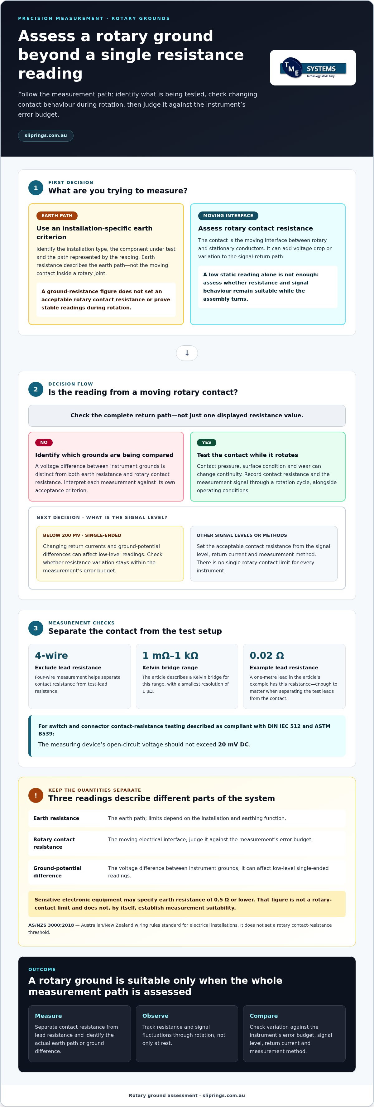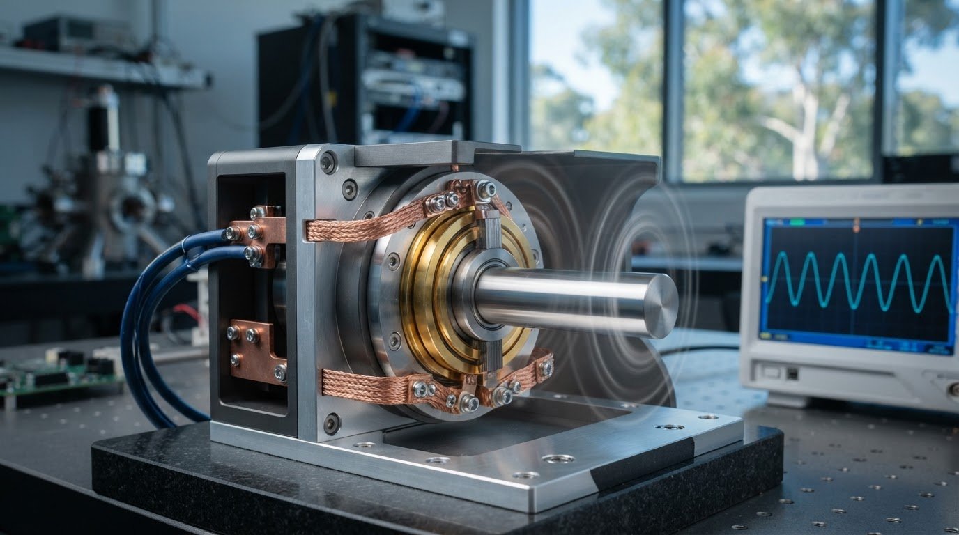
A low resistance rotary ground for sensitive measurements must maintain stable electrical contact while turning; a low static reading alone isn’t enough. Sensitive electronic equipment may have a specified ground resistance of 0.5 Ω or lower, but that earth-resistance threshold is different from the rotary contact resistance and doesn’t, by itself, establish measurement suitability.
A ground connection should provide a dependable reference throughout operation. In a rotating assembly, however, contact conditions can change as it moves, affecting return current and potentially disturbing low-level readings. Understanding this distinction helps you assess the complete measurement path rather than relying on a single resistance value.
This article explains how contact resistance is assessed, why ground-resistance thresholds vary by application, and what continuous rotation can reveal about a rotary ground. You’ll also learn why measurements below 200 mV can be sensitive to changing ground-potential differences, and which electrical and mechanical factors matter when evaluating rotary ground suitability for precision work.
Key Takeaways
- Separate rotary contact resistance from earth resistance: they describe different parts of the electrical path and affect measurement suitability in different ways.
- Use the ground-resistance threshold for the application. Sensitive electronic equipment may specify 0.5 Ω or lower, but that figure alone doesn’t set an acceptable rotary contact resistance.
- Assess contact stability while the assembly rotates, not just at rest. Conventional rotary ground clamps showed current variation of more than 100 amps during rotation in a demonstration.
- For low-level single-ended measurements below 200 mV, changing return currents and ground-potential differences can affect readings.
- Compare rotary electrical contacts against your measurement needs, circuit count, current, speed and mounting requirements to narrow the suitable options.
Contact resistance in rotary grounds
Contact resistance is the electrical opposition at the moving interface between rotary and stationary conductors. In a measurement circuit, that interface can add voltage drop or variation to the signal-return path.
Rotary Contact Types
A slip ring transfers current through sliding contacts between a rotating ring and stationary brushes, while a rotary ground brush provides a dedicated conductive path. Mercury-wetted contacts use a liquid interface instead. Noise and resistance behaviour depend on contact design, operating conditions and circuit requirements, so no type is automatically best for every measurement.
Wear can change a sliding interface, while variations in contact pressure or surface condition can disturb continuity. These changes may cause ground-potential shifts or ground-loop currents, adding offsets to measurements. Compare contact behaviour during rotation, not just at rest, and consider how the path carries both signal return and other currents.
Acceptable Contact Resistance
Acceptable contact resistance is the level that keeps resistance-related voltage error within the measurement’s error budget. No single rotary-contact limit suits every instrument: the allowable value depends on signal level, return current and measurement method.
For context, sensitive electronic equipment may specify earth resistance of 0.5 Ω or lower; that is not a rotary-contact limit. Low-level single-ended measurements below 200 mV can be sensitive to ground-potential fluctuations. AS/NZS 3000:2018 is the Australian/New Zealand wiring rules standard for electrical installations, but it doesn’t set a rotary contact-resistance threshold.
Resistance and Noise Measurement
Accurate measurement separates the contact’s resistance from test-lead resistance and records changes while the joint rotates. A Kelvin bridge is typically used for 1 mΩ to 1 kΩ, with a smallest resolution of 1 μΩ. Four-wire measurement helps exclude lead resistance; a one-metre lead in the example has 0.02 Ω resistance.
For switch and connector contact-resistance testing described as compliant with DIN IEC 512 and ASTM B539, measuring-device open-circuit voltage should not exceed 20 mV DC. To assess noise, monitor the measurement signal and contact resistance through a rotation cycle, noting fluctuations alongside operating conditions.
Low-Resistance Ground Path Design
Design a low-resistance rotary ground path by separating sensitive signal returns from higher-current paths and minimising unnecessary connections. Match the contact arrangement to circuit count, current and rotation, then assess whether resistance variation stays within the instrument’s error budget.
Keep excitation grounds and single-ended sensor returns near their signal terminals on the same terminal block. Place shield connections near the sensor signal terminals, and use differential measurement when sensor and data-logger grounds differ. For a low-resistance rotary ground for sensitive measurements, assess shielding, isolation and the complete return path together.
Ground resistance thresholds
Ground-resistance limits depend on the installation and the function of its earthing system. They describe the earth path, not the moving contact inside a rotary joint. In power systems, commonly cited figures include 4 Ω as the maximum working ground resistance, 4 Ω as the maximum protective ground resistance and 10 Ω as the maximum repeated ground resistance. These values apply to distinct grounding functions, so they aren’t interchangeable acceptance limits.
Other installation types use different reference points:
- Industrial and commercial installations often regard 1 Ω or less as good, while some standards allow up to 5 Ω.
- Telecommunications guidance commonly gives 5 Ω or less for sensitive equipment.
- Substation valve-type lightning arresters have a cited maximum of 5 Ω.
- Residential settings typically regard 5 Ω or less as acceptable.
Utility earthing also varies by system arrangement. An overall earth value of 0.3-0.5 Ω is cited for utility pole earth systems, while individual electrodes typically need to be below 10-20 Ω. Those figures describe different parts or configurations of an earthing system. Don’t treat an individual electrode target as equivalent to an overall system value.
A test result depends on which parts of the earthing system form the measured path. For example, a clamp-on reading can represent a combined loop rather than one electrode alone. In a described transformer arrangement, a 40 Ω measurement represents two earths in series; it doesn’t establish whether each electrode system meets its own target. The test configuration matters as much as the displayed resistance.
Keep three quantities distinct when assessing a rotary measurement system: earth resistance, rotary contact resistance and the voltage difference between instrument grounds. An earth-resistance target does not define acceptable contact noise during rotation. Meeting an earth threshold also does not show that a signal return stays stable as current changes. Each measurement describes a different part of the electrical system and needs its own acceptance criterion.
Interpret a threshold by identifying the installation type, the component under test and whether the reading represents an individual electrode or a combined path. Then compare it with the criterion intended for that arrangement. A 5 Ω target for a residential earth, for example, doesn’t automatically apply to a utility pole electrode or a substation arrester. The application determines which reference is relevant.
For precision instrumentation, use the applicable earthing target to assess the earth system, then evaluate the rotary path separately. This prevents an acceptable ground-resistance result from being mistaken for proof of suitable rotating-contact performance. Record the test configuration with the result, particularly when clamp-on measurements include multiple earth paths or connected equipment.
Rotary ground performance during continuous rotation
A rotary ground must maintain electrical continuity while its contact surfaces move relative to each other. A stationary resistance reading captures only one position, not the changes that may occur across a full rotation. In a demonstration, current through conventional rotary ground clamps varied by more than 100 amps as the clamps rotated. That result shows why a single at-rest reading can miss performance changes during operation.
Sliding contacts can respond to changes in contact pressure, surface condition and alignment. As the component rotates, these variations can alter the electrical path and change current or voltage. A sensitive instrument may register the changes as noise, an offset or intermittent readings. The practical question is not just whether a connection conducts, but whether it behaves consistently through the required movement.
Assess performance under representative operating conditions. Keep the electrical load, measurement arrangement and rotation pattern consistent so you can compare changes meaningfully. Record the electrical signal alongside the rotation position. For example, a reading that shifts at the same point in each rotation may indicate a position-related contact change. Irregular fluctuations suggest a different pattern that also needs investigation.
Compare more than average resistance. Track the minimum, maximum and variation over the rotation, and note any interruptions or unstable readings. A stable average can conceal brief changes that affect an instrument’s output. For a ground connection carrying return current, observe current and voltage together: a current change may help explain a corresponding shift in measured ground potential.
Separate rotary-contact effects from other parts of the test circuit. Secure stationary connections, keep measurement leads arranged consistently, and avoid moving cables while the assembly turns. If the signal changes, repeat the same rotation pattern and compare results. This helps distinguish contact variation from a loose terminal, cable movement or changing load elsewhere in the circuit.
Test at the operating speed and load required by the application, rather than relying only on slow manual rotation. Record the conditions for each run, including rotation direction and whether the system is carrying its usual current. These details make later comparisons useful when alignment, contact condition or circuit loading changes. Assess a low-resistance rotary ground for sensitive measurements as a moving electrical path, considering variation alongside the resistance reading.
For precision systems, treat continuous-rotation testing as part of design validation. Compare the resulting signal variation with the instrument’s allowable measurement error, then assess whether the contact type and return-path layout suit that requirement. The demonstration’s variation of more than 100 amps applies to the conventional clamps tested; it isn’t a universal result for every rotary ground. The useful outcome is a repeatable record of performance in the actual operating arrangement.
What rotary ground contact resistance is acceptable for precision measurements?
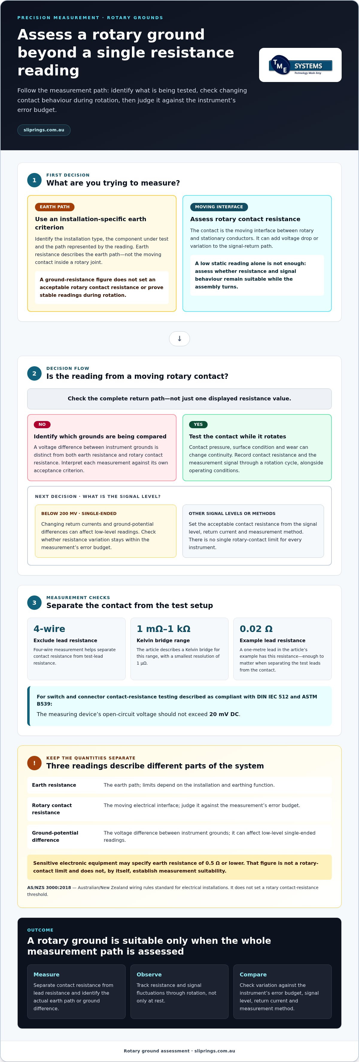
There is no single contact-resistance limit for every precision instrument. Set an acceptance criterion based on the instrument’s allowable error, circuit current and required repeatability. Then assess the rotary connection against that criterion in the assembled circuit, rather than applying an earth-resistance target to a moving contact.
Current matters because electrical power loss is calculated as current squared multiplied by resistance. The same contact resistance can therefore have different consequences in circuits carrying different currents. For a low-current sensor return, resistance variation may be the main concern because it affects the reading. For a higher-current path, resistance-related heating also matters. Include both effects when defining the acceptable range.
Separate the contact from the rest of the measurement path. Establish a baseline with the rotary interface stationary, then compare readings as it moves under the intended electrical load. Record the resistance range, not just one value or an average. The acceptance criterion should account for the highest observed resistance and any variation that could affect the instrument’s specified performance.
Temperature must also be controlled when comparing resistance readings. Near room temperature, copper has a temperature coefficient of +0.393% per °C, while aluminium has a coefficient of +0.4100% per °C. These figures describe changes in conductor resistance with temperature, not a limit for the rotary contact. Record test temperature so a change in the measured path isn’t mistaken for contact deterioration.
Before testing, identify which conductors and connections are included in the measurement. A result across the whole assembly can combine resistance from the rotary interface, terminals and fixed wiring. Keep measurement points consistent between tests and document the circuit configuration. This makes readings comparable when the installation or contact condition changes.
Use the following decision sequence to set and apply an acceptance criterion:
- Start with the instrument’s allowable measurement error and required repeatability.
- Identify the current flowing through the contact during the measurement.
- Measure the assembled path at consistent points and operating conditions.
- Compare stationary and rotating results, including the full observed range.
- Record temperature and circuit configuration alongside each result.
A resistance figure is meaningful only in relation to the measurement circuit and its operating conditions. If the stationary reading meets the design criterion but the rotating result exceeds it, the contact is unsuitable for that defined duty. If both remain within the criterion, assess the completed system against its other electrical and mechanical requirements before specifying the connection.
Acceptable resistance levels ultimately depend on the entire measurement path and the error the instrument can tolerate. A ground resistance of 25 ohms or less might be acceptable in some cases, but that figure is not a universal acceptance limit for a rotary contact. The decision still depends on the circuit and the measurement being made.
A 1 mV ground-potential difference between a thermocouple sensor in soil or water and the data logger ground can add 1 mV to the measured voltage. This illustrates why ground-related effects should be considered alongside contact resistance: assess whether the resulting change is acceptable for the instrument, and keep the grounding arrangement consistent during comparisons.
Which rotary electrical contacts provide low noise and stable resistance?
No contact type is automatically best for every precision circuit. Compare the contact mechanism, resistance variation during rotation, signal level and return current. A suitable rotary electrical contact must keep unwanted voltage changes within the measurement system’s error budget, not merely provide continuity at rest.
Conventional rotary ground clamps commonly use a conductive ring or band made from copper, brass or bronze around a rotating conductive stud. Some designs feed conductive grease into the gap between stationary and rotating parts. These details describe the contact path, but do not establish its noise or resistance stability in a particular assembly. Assess the actual connection under its intended rotation and electrical load.
Slip rings transfer electrical paths across a rotating interface, typically using stationary contacts against rotating conductive rings. Rotary ground brushes provide a grounding contact path, while mercury-wetted contacts use mercury at the electrical interface. Each mechanism has different construction and operating considerations. Compare measured resistance variation and signal noise for the intended application, rather than assuming one contact type will suit every instrument.
Liquid metal rotary connectors are brushless rotary connectors that use a pool of conductive liquid metal to maintain electrical continuity, eliminating wear and reducing noise. This contact method differs from sliding brush contacts. Its suitability still depends on circuit requirements and the complete application, including current, signal type and mechanical arrangement. The operating principle is a useful comparison point when assessing contacts for precision measurements.
Make the comparison practical by testing each candidate in the intended circuit:
- Measure contact resistance with a four-wire method to reduce test-lead influence.
- Record resistance and signal variation throughout rotation, not only at a stationary position.
- Keep the test load and measurement arrangement consistent between contact types.
- Compare observed noise with the instrument’s allowable measurement error.
A resistance value alone can hide short interruptions or position-related changes. For example, a contact may show a low average while its signal varies at particular points in the rotation. Capture both resistance and the measured signal over the operating cycle. This helps distinguish electrical contact behaviour from noise entering elsewhere in the circuit.
Choose the contact method by matching its measured performance to the instrument’s needs. Record the circuit configuration, current and rotation conditions alongside test results, so comparisons remain meaningful when the design changes. To review rotary slip-ring options against your application requirements, explore rotary slip-ring configurations.
Electrical power loss in a system is calculated as current squared multiplied by resistance. The guide gives an example in which a motor field winding’s resistance increases from 1.3245 Ω cold to 1.7654 Ω after eight hours at full load, corresponding to a calculated temperature rise of 84.702 °C. This underscores why resistance should be considered under operating conditions.
TME Systems: Mercotac Slip Rings
TME Systems helps match rotary electrical requirements with suitable slip-ring options, including Mercotac Slip Rings. Selection for a measurement system can account for circuit count, current, voltage, rotational speed, mounting style and environmental conditions. These details help identify a product that suits both the mechanical assembly and its electrical duties.
For a different contact approach or configuration, TME Systems also supplies Meridian Laboratory Slip Rings, BGB Innovation Slip Rings and Prosper Rotation Slip Rings. Share your application requirements and measurement priorities to focus the technical discussion on suitable options.
Contact TME Systems or visit sliprings.com.au to discuss your rotary ground application.
Define the measurement requirements before selecting a contact
Before specifying a rotary ground, turn your measurement needs into design criteria. Record the signal type, allowable measurement error, return-current path, rotation conditions and installation constraints. These details give engineers a practical basis for assessing whether a contact arrangement suits the complete system.
A low-resistance rotary ground for sensitive measurements is not selected by resistance alone. The contact must behave appropriately for the instrument and its operating circuit. Treat the measurement setup as one system, including the sensor, data logger, shielding and rotary interface. This helps clarify which requirements are fixed and where a different contact method or mounting arrangement may be appropriate.
TME Systems can discuss your application and slip-ring requirements in relation to circuit count, current, voltage, speed and mounting style. Bring the relevant electrical and mechanical details to the discussion to keep selection focused on your measurement task.
Discuss your measurement application with TME Systems, and take the next step towards a rotary connection suited to your design.
Frequently Asked Questions
What does a rotary ground connection do in a measurement system?
It provides an electrical reference across a rotating interface. In a test-rig schematic, label whether the connection carries the sensor reference, a shield or both, and distinguish it from the chassis connection. This helps technicians trace the intended circuit during commissioning and prevents a chassis continuity check from being mistaken for a check of the measurement return path.
What Australian suppliers sell low-noise, low-resistance slip rings, and what do they cost?
TME Systems is associated with Mercotac slip rings.