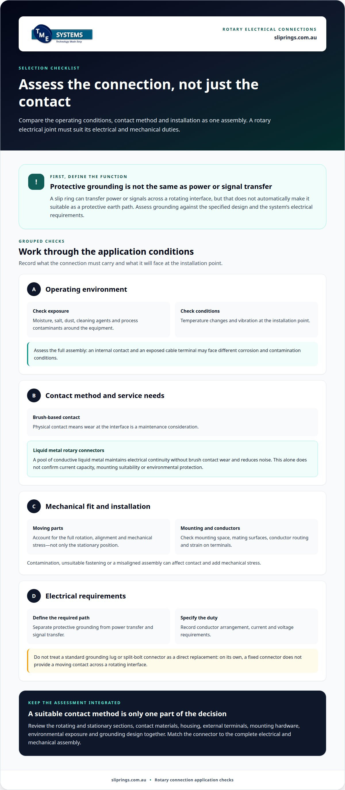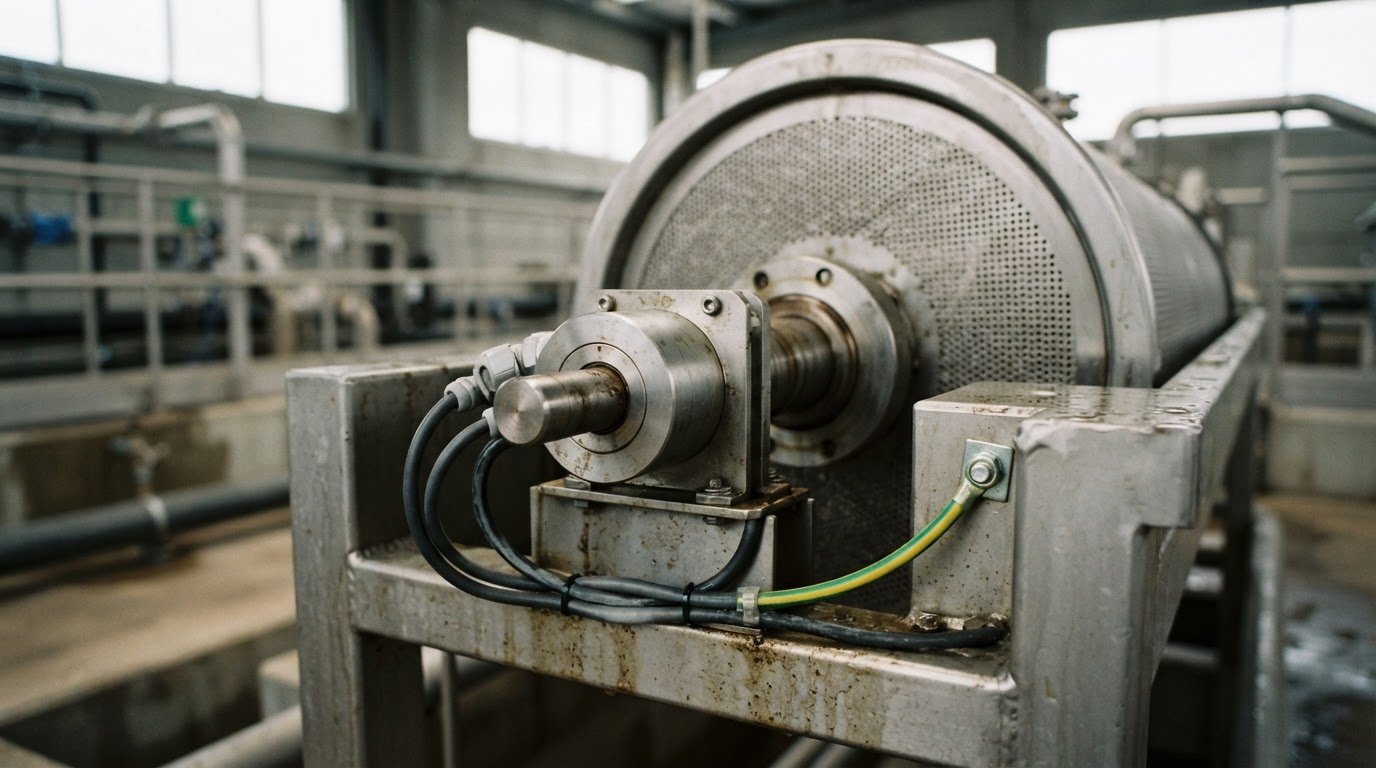
A Panduit rotary ground alternative may involve a slip ring or rotary electrical joint that maintains electrical continuity across a rotating interface. Some liquid metal rotary connectors offer a maintenance-free contact method, but a rotary connector is not automatically a substitute for a protective earth bond. The design must meet the grounding requirements of the application.
Looking beyond conventional rotary grounding arrangements can make sense when servicing access, contact wear or installation complexity is a concern. The right option depends on what the connection must carry, including current and signals, as well as rotational speed, mounting style and operating environment.
This article explains how rotating electrical connections work, where liquid metal technology may fit and which application details guide selection. It also covers mounting options and how technical application consulting can help match a connector to mechanical and electrical requirements.
Key Takeaways
- A rotating electrical connection can transfer power or signals between stationary and rotating components; its suitability depends on the application’s electrical and mechanical requirements.
- Assess current, voltage, circuit count, rotational speed, mounting style and operating environment before selecting a slip ring or rotary electrical joint.
- Material and contact method affect wear, corrosion exposure and maintenance needs, so compare them against the conditions the connection will face.
- A grounding lug or split-bolt connector may suit a fixed connection, but it does not by itself provide a continuous electrical path across rotating parts.
- TME Systems Pty Ltd’s technical application consulting can help match Mercotac, Meridian Laboratory, BGB Innovation or Prosper Rotation slip rings to your application.
Maintenance-free rotating electrical connections
A rotating electrical connection transfers power or signals between stationary and moving components while allowing rotation. A slip ring or rotary electrical joint can provide that path, but it does not automatically replace a protective grounding connection.
Material and durability comparison
Material selection affects contact performance, corrosion exposure and service requirements. Assess the conductive contacts, housing and external terminals separately: a suitable contact method can still be undermined by corrosion at an exposed terminal or an incompatible mating surface. For coastal machinery, washdown equipment or dusty plants, consider moisture, contaminants, temperature changes and vibration at the installation point.
Brush-based designs use physical contact, so wear at the interface is a maintenance consideration. Liquid metal rotary connectors use a pool of conductive liquid metal to maintain electrical continuity, avoiding brush contact wear and reducing noise. This may suit applications where contact wear is a concern, but it does not establish that every liquid metal design has the required current capacity, mounting arrangement or environmental protection. Match the connector’s materials and construction to the full operating environment.
Connector replacement options
A standard grounding lug or split-bolt connector may join conductors in a fixed installation, but neither provides a moving contact across a rotating interface on its own. A rotating assembly needs an engineered electrical path between its stationary and rotating sections. Treating a static connector as a direct replacement can leave the rotating connection without the continuity the application requires.
When considering a Panduit rotary ground alternative, first define whether the required path is protective grounding, power transfer or signal transfer. Then establish the conductor arrangement, current and voltage requirements, rotation, mounting space and environmental conditions. A slip ring may provide the rotating transfer function, but its suitability for grounding depends on its specified design and the system’s electrical requirements. Do not assume that transferring power or signals makes a connector suitable for protective grounding.
Risks of incompatible or incorrect installation
An incompatible connector can lose reliable electrical contact as the assembly moves, or prove unsuitable for the current, mechanical load or environment. A poor fit may also strain conductors or terminals. In a rotating application, movement changes how components meet, so the design must account for the full rotation, not just the stationary position.
Incorrect installation can undermine contact between conductive surfaces. Contamination, unsuitable fastening or conductor strain may affect continuity, while a misaligned rotating assembly can add mechanical stress. These conditions can create electrical or equipment hazards, particularly if a protective grounding path is assumed rather than engineered. Keep grounding separate from other circuit functions and assess the connector as part of the complete electrical and mechanical assembly.
Start selection by recording the required function and operating conditions. Separate protective grounding from other power and signal circuits, then identify the rotation, conductor arrangement, current, voltage, mounting space and environmental exposure. These details help distinguish a rotary electrical joint from a fixed connector and narrow down the appropriate contact approach.
Next, consider maintenance access. A brush-based slip ring may suit an installation if its contact arrangement and service needs fit. Liquid metal technology avoids contact wear at the interface, but still needs to match the electrical duty and mechanical configuration. “Maintenance-free” should describe a specific contact method or maintenance requirement, not serve as a blanket promise about the entire assembly.
Finally, review the connection as an integrated system. The rotating and stationary sections, conductor routing, mounting, environmental protection and grounding design all affect performance. If the required function is a protective earth path, assess it on that basis rather than assuming a general-purpose rotary connector will fulfil it. This distinction helps prevent a static lug or split-bolt from being specified for a connection that must maintain continuity during rotation.
How do Panduit rotary ground alternatives compare on material, corrosion resistance, and durability?
Compare each rotary connection by its conductive contacts, housing, terminals and mounting hardware. These parts face different stresses, so a material suitable for one may not suit another. For example, a protected internal contact and an exposed cable termination face different moisture and contamination conditions. Assess the complete assembly against the conditions at its installation point.
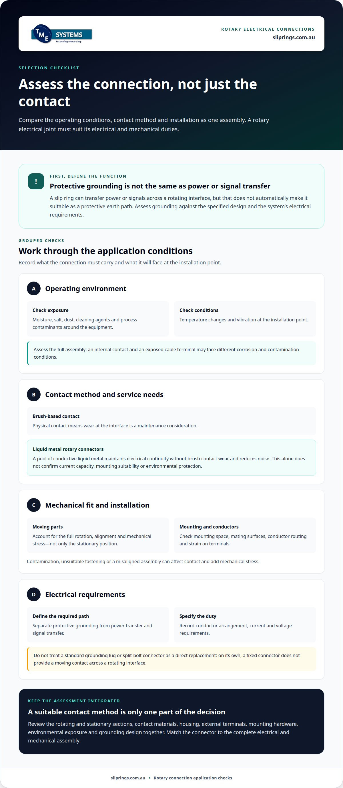
Start with the operating environment, then consider materials and contact method together. A useful comparison records:
- Exposure: moisture, salt, dust, cleaning agents and process contaminants around the equipment.
- Contact arrangement: whether the design uses physical contact or liquid metal technology.
- Mechanical conditions: vibration, alignment, rotation and strain on attached conductors.
- Installation details: the mating surfaces, mounting method and access for inspection or servicing.
These points help distinguish a practical material advantage from a label alone. A corrosion-resistant housing, for instance, does not establish that every terminal or fastener has the same resistance. Likewise, a durable contact method cannot compensate for a poorly supported cable or unsuitable mounting interface. Compare exposed and internal parts separately.
Corrosion depends on the materials in contact and the surrounding conditions. In coastal installations, airborne salt and moisture can affect exposed metal surfaces. In food-processing areas, cleaning chemicals may create a different exposure. Check documented material compatibility against the actual environment, including nearby metals and how surfaces are joined. Do not assume two metals will behave alike simply because both are conductive.
Electrical continuity also depends on the interface between connected parts. Oxide, contamination or surface damage can affect that interface, while movement can add mechanical stress. For example, a rotary joint mounted beside a vibrating drive may experience combined movement. Assess contact surfaces, conductor support and alignment as one assembly instead of comparing material names in isolation.
Durability should be considered as a maintenance question, not just a materials question. A brush-based contact has a physical interface that may wear during operation. Liquid metal technology avoids a brush-based contact interface, which can inform maintenance planning. That design distinction can help frame the comparison, but operating conditions and the selected connector’s construction still matter.
Use a practical comparison process. First, map exposure at the installation point, including moisture, salt, dust and cleaning chemicals. Next, identify the material of each exposed contact, terminal and fastener from product documentation. Then assess interfaces for dissimilar materials, contamination and mechanical strain. Finally, compare the contact method with maintenance access and operating conditions.
This process also clarifies what “corrosion resistance” means for the installation. A protected housing may limit exposure to internal components, while terminals remain open to the environment. A coating may protect a surface, but assembly damage can expose the underlying material. Include cable entry points, fasteners and mating faces in the review, not just the connector body.
For a Panduit rotary ground alternative, prioritise verified material compatibility and the complete duty cycle over a single durability claim. Record the environment, contact arrangement and mounting interface together. This gives engineers a sound basis for comparing options and identifying where corrosion, wear or mechanical stress could affect the connection.
Can a standard grounding lug or split-bolt connector replace a Panduit rotary ground connector?
Once the rotating interface has been addressed, a grounding lug or split-bolt may still suit a fixed conductor joint elsewhere in the assembly. The choice depends on the conductor, terminal arrangement, mechanical support and installation environment. Treat the connector as one part of the grounding path, not as a substitute for assessing the complete electrical design.
A lug provides a termination point, while a split-bolt joins conductors. To assess either option, start with the conductor material and construction. The connector must suit the conductors being joined and the intended termination method. Also consider how the connection will be supported, protected and accessed after installation. Select for the actual joint, not just the connector’s general category.
Review these details for each fixed connection:
- Conductor compatibility: confirm the connector is intended for the conductor materials and sizes in the design.
- Contact surfaces: consider the terminal finish, mating surface and exposure to contamination or corrosion.
- Mechanical support: assess whether cable weight, vibration or movement could strain the termination.
- Protection and access: consider enclosure, environmental exposure and how the joint can be inspected.
- Grounding function: keep the intended protective path distinct from power and signal connections.
For example, a lug mounted to a fixed panel may provide a defined termination point if its conductor and mounting arrangement suit the design. A split-bolt may suit a fixed splice when the conductors and installation conditions are compatible. In either case, conductor routing matters. A cable that transfers vibration or mechanical load to the joint can affect the connection over time, which is why protective bundling solutions from suppliers such as Abbey Extrusions are often used to isolate and shield wiring runs from continuous friction.
Material compatibility matters at the termination. Dissimilar metals, moisture and contaminants can affect the joint’s condition. The enclosure or protective treatment should reflect the site environment, such as a washdown area or exposed outdoor installation. A connector’s material alone does not establish the corrosion performance of the complete joint: mating surfaces and surrounding conditions matter too.
Installation quality also affects selection. Prepare and secure the conductor according to the connector’s instructions. Poor contact, loose fastening or cable strain can undermine the intended electrical connection. Plan how to inspect the finished joint, and ensure it can be accessed without disturbing adjacent wiring or the rotary assembly.
Document each connection’s role in the drawing or equipment schedule. Show which joints are fixed terminations, which circuits cross a rotating interface and how the protective grounding path is formed. This makes review clearer for design, installation and maintenance teams. It also reduces the risk of selecting a lug or split-bolt based only on physical fit.
For Australian projects, apply the relevant electrical installation requirements and project design to the complete grounding arrangement. A fixed connector may suit a fixed joint, but suitability depends on its intended use, compatible conductors and installation conditions. The design must also account for how the grounding path remains effective throughout the equipment’s operation.
Use the connector documentation and system design to resolve those details before specifying hardware. Review rotating slip ring configurations alongside the fixed terminations in your application, so each connection has a defined role.
Distinguish between a stationary termination and a connection that must accommodate rotation. A lug or split-bolt can be assessed for a fixed joint, but should not be treated as an automatic substitute when the grounding path crosses a moving interface. In that situation, address the interface requirement first, then assess fixed joints separately. This helps ensure each connector suits its intended role. If the design includes both a rotating interface and fixed conductor joints, assess each part of the path on its own terms while confirming the complete grounding arrangement is appropriate.
Meridian Laboratory offers more than 350 standardised ROTOCON slip ring configurations. That range can be a useful starting point when identifying an interface option for a design that requires rotation; it does not establish that any particular configuration suits a given installation. Compare the actual requirements of the moving connection with the details of the proposed interface, and assess conductor terminations separately for material, support, protection and access. If the design instead has only a fixed joint at the location in question, a compatible lug or split-bolt may be considered for that joint. The decision should follow the movement and grounding requirements of the assembly, rather than connector category alone. Keep installation instructions and inspection needs in view, and confirm that each connection contributes to the intended grounding path without imposing mechanical strain on another part of the assembly.
TME Systems Pty Ltd
TME Systems Pty Ltd helps Australian engineers assess slip ring options for rotating electrical applications. If you are considering a rotary connection, its technical assistance can help match requirements such as circuit count, current, voltage, speed, mounting style and operating environment with an appropriate product range.
Options include Mercotac Slip Rings, Meridian Laboratory Slip Rings, BGB Innovation Slip Rings and Prosper Rotation Slip Rings. Technical selection can help determine whether a slip ring suits the required power or signal transfer and installation configuration. Do not assume a rotary connector replaces protective grounding unless the connector and system design are suitable for that specific function.
Contact TME Systems Pty Ltd to discuss your rotating electrical connection and application requirements.
Plan the next step for your rotating connection
Before releasing a design, schedule a review where mechanical and electrical teams can resolve interface questions together. This helps ensure the selected Panduit rotary ground alternative is considered as part of the equipment design, not introduced late after surrounding components are fixed.
A clear design handover can record the selected configuration, installation constraints and responsibility for final approval. This gives procurement and engineering teams a shared reference as the project moves towards specification and integration.
For a technical discussion about your project, start a conversation with TME Systems Pty Ltd. A focused review can help move the design towards its next decision.