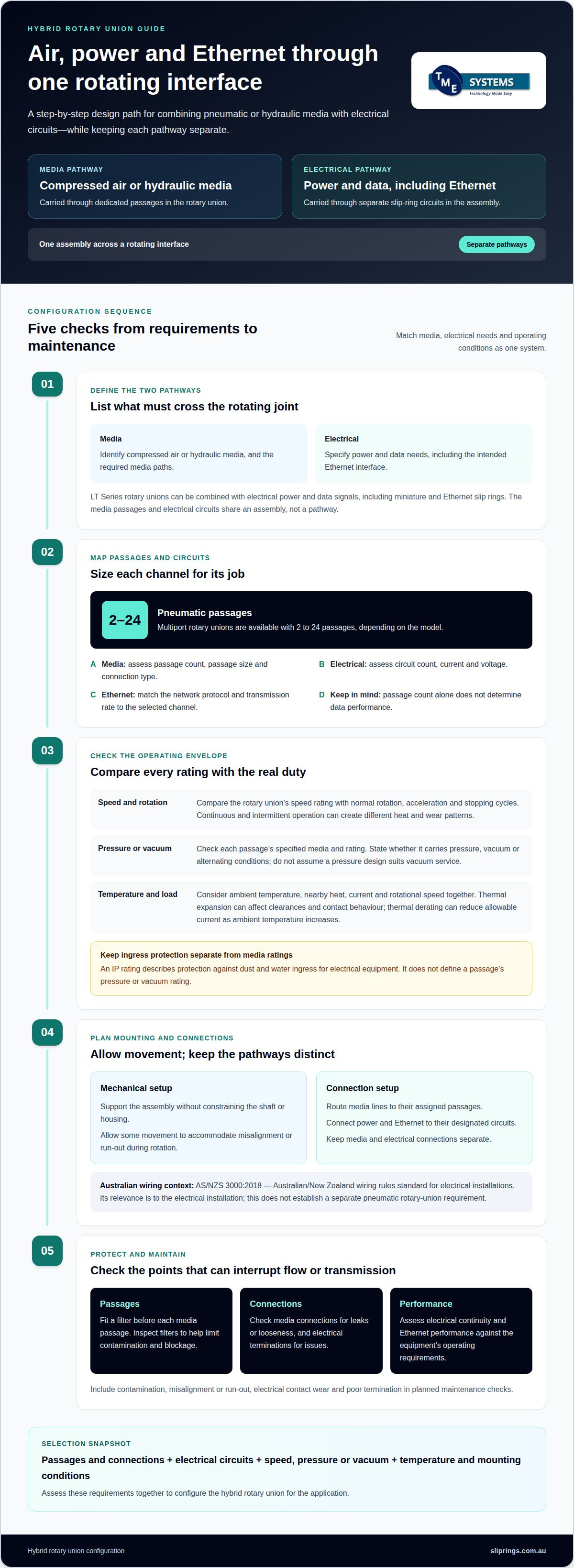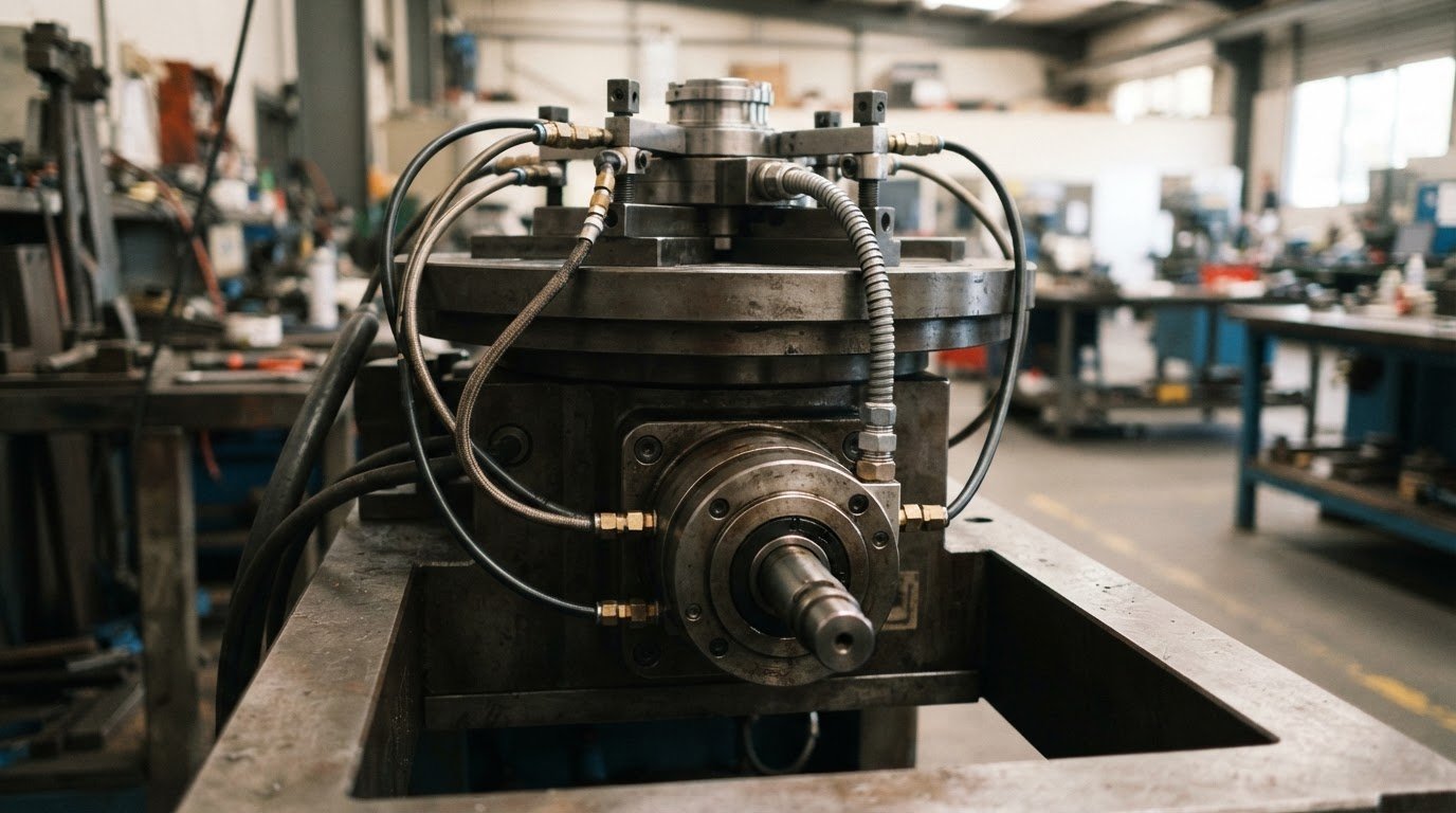
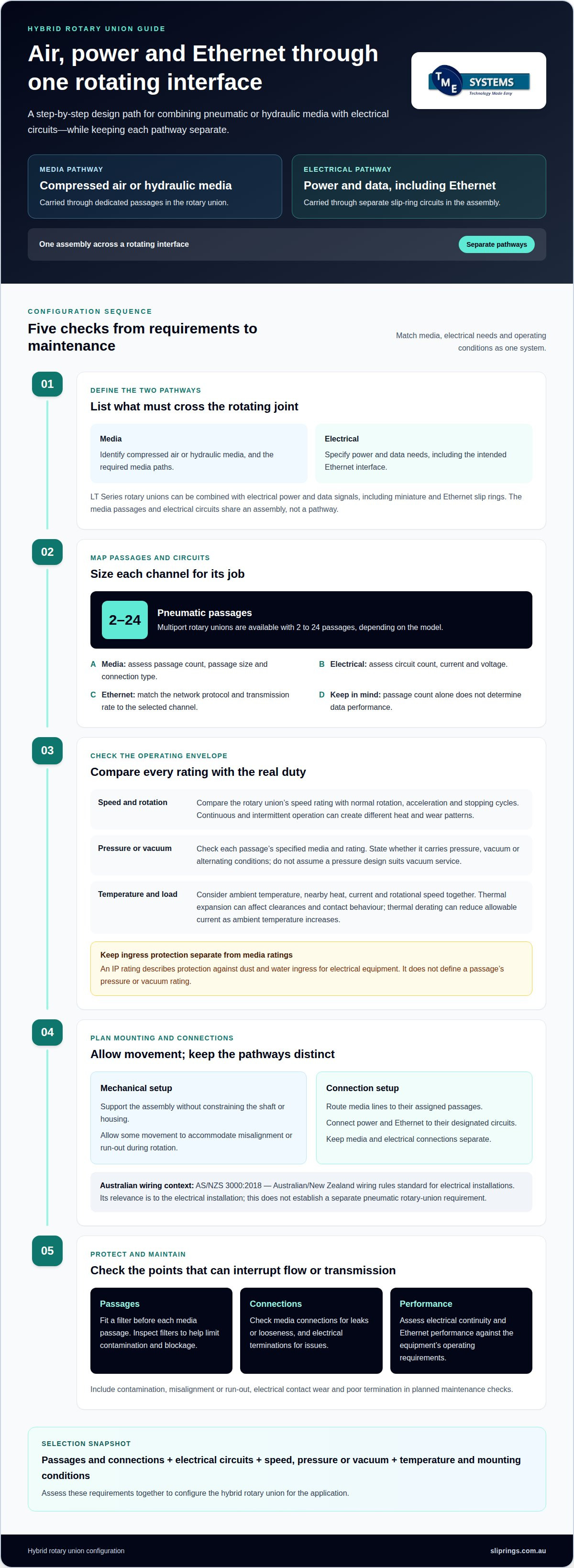
A rotary union can carry pneumatic media alongside Ethernet and electrical power when each path is matched to the required signal, flow and operating conditions. Combining pneumatic lines and Ethernet in one rotary union lets data and media cross a rotating interface within one assembly, while keeping their pathways separate.
That integration still depends on the details: passage count and size, connection type, circuit requirements, speed, pressure and mounting arrangement all affect the configuration. Multiport pneumatic rotary unions are available with 2 to 24 passages, depending on the model.
This guide explains how electrical power and data signals can be integrated with pneumatic or hydraulic media, which channel and connection options are available, and how circuit combinations and operating limits shape the design. It also covers the engineering considerations that help maintain reliable operation, including managing alignment and keeping media passages clean.
Key Takeaways
- Hybrid rotary unions can carry electrical power and data alongside pneumatic or hydraulic media through one rotating interface.
- Passage count, bore and connection type shape the media configuration; available options vary by model.
- Pressure, rotational speed and temperature affect operating limits, so assess them together with the application’s media and electrical requirements.
- Allow for alignment movement and use filtration to help keep media passages clear during operation.
- TME Systems’ technical application consulting can help match slip ring options to circuit count, current, voltage, speed, mounting style and environmental requirements.
Combined electrical power and signal transmission with pneumatic or hydraulic media
A hybrid rotary union combines fluid passages with electrical paths across a rotating interface. Combining pneumatic lines and Ethernet in one rotary union requires matching the media circuits and slip ring to the application’s operating requirements.
Pneumatic and electrical channel combinations
LT Series rotary unions can be combined with electrical power and data signals, including miniature and Ethernet slip rings. Separate passages carry compressed air or hydraulic media, while electrical circuits transfer power or signals through the rotating joint.
Assess passage count and size alongside circuit count, current, voltage and data requirements. Ethernet and power have different transmission needs, so the electrical configuration must suit the intended signals as well as the pneumatic or hydraulic layout.
What types of rotary unions support both compressed air and Ethernet? Hybrid rotary unions with pneumatic passages and an Ethernet slip ring support both. The right configuration depends on the required media paths and electrical circuits.
How do pneumatic rotary unions and Ethernet slip rings work together? The rotary union maintains media flow through passages as its sections rotate, while the slip ring maintains electrical connections for power or data. They share an assembly but use separate pathways.
Ethernet protocols and data rates depend on the electrical interface and slip-ring configuration. Match the required network protocol and transmission rate to the selected Ethernet channel. Passage count alone does not determine data performance.
Installation and wiring
Installation focuses on mounting alignment, media routing and electrical termination. Support the assembly without constraining the rotary union shaft or housing. Allowing some movement can accommodate misalignment or run-out during rotation.
Route air or hydraulic lines to their assigned passages, then connect power and Ethernet to their designated circuits. Keep media and electrical connections separate, and fit a filter before each media passage to limit particles entering the channels.
In Australia, AS/NZS 3000:2018 is the Australian/New Zealand wiring rules standard for electrical installations. Its relevance is to the electrical installation; this does not establish a separate pneumatic rotary-union requirement.
Failure modes and maintenance
Contamination can obstruct a passage, while misalignment or run-out can add mechanical stress during rotation. Electrical contact wear or poor termination can also interrupt power or data transmission. Include these areas in planned maintenance.
Fit filters ahead of each media passage and inspect them as part of routine system maintenance. Check connections for leaks or looseness, and assess electrical continuity and Ethernet performance against the equipment’s operating requirements.
Which Australian suppliers sell pneumatic rotary unions with Ethernet? Industrial rotary-union suppliers handle this type of requirement; selection should account for both the media passages and Ethernet slip-ring needs.
Operating pressure, speed and temperature limits
A hybrid rotary union must suit the application’s pressure, rotation and thermal conditions. Assess compressed air or vacuum requirements alongside the electrical load and operating environment.
Operating speeds
The selected rotary union’s speed rating sets its maximum operating speed. Compare that rating with the machine’s normal rotation and any acceleration or stopping cycles. Intermittent operation can produce different heat and wear patterns from continuous rotation.
Speed also affects seal behaviour, bearing loads and electrical contact performance. For example, a unit carrying compressed air during continuous rotation must maintain media sealing and signal continuity under that duty. Assess pneumatic and Ethernet requirements together, rather than treating the slip ring’s speed as the only limit.
Pressure limits depend on the rotary union’s passage design, seals and specified media. Compare the required operating pressure with the rating for the selected model and each passage. Pressure differences between adjacent channels can also affect sealing, so include every circuit’s pressure conditions in the operating profile.
Vacuum service has different sealing demands from positive-pressure compressed air. State whether each passage carries vacuum, pressure or alternating conditions. Do not assume a rotary union designed for air pressure is suitable for vacuum; match its seal arrangement and operating specification to the duty.
Temperature and protection ratings
Assess ambient temperature and operating heat together. Electrical current, rotational speed and nearby equipment can contribute to temperature rise. Thermal expansion may affect clearances and contact behaviour, while thermal derating can reduce allowable current as ambient temperature increases.
Record the expected temperature range around the installed unit, including heat from nearby machinery. Compare it with the rotary union and slip-ring specifications to establish whether the combined assembly can handle the media and electrical loads at the same time.
An IP rating describes protection against dust and water ingress for electrical equipment. It does not define a pneumatic passage’s pressure or vacuum rating. Check the installation’s protection requirements separately from the fluid performance requirements.
Before selection, document operating speed, pressure or vacuum, ambient temperature, electrical load and required IP rating. Use the most demanding condition for each parameter, including start-stop cycles and changes in media conditions. This gives the rotary union design a clear set of operating limits.
Hybrid rotary union channel configurations
A hybrid layout assigns separate paths to media, electrical power and data. Start with the machine’s connections and required circuits to determine the right arrangement.
To select a combined pneumatic rotary union and Ethernet slip ring, list every media passage and electrical circuit, then match them to a compatible assembly. Include Ethernet requirements, power loads, connection positions and the machine’s available mounting space.
LT Series multiport pneumatic rotary unions are available with 2 to 24 passages, depending on the model. That range helps frame passage planning, but passage count alone does not determine whether a particular layout suits the application. Specify what each passage carries, such as compressed air, and whether separate media paths are needed.
Keep fluid and electrical functions separate in the configuration. Pneumatic passages carry media through the rotary union; electrical channels carry power or signals through the slip ring. Ethernet data needs an appropriate Ethernet slip ring, while power uses circuits selected for its load. Combining them in one assembly does not make the channels interchangeable.
Create a channel schedule before choosing a layout. For example, an application may need separate compressed-air paths alongside Ethernet data and electrical power. Record each path’s purpose, connection point and operating requirement. This gives the design a clear basis for allocating channels and identifying connection conflicts.
- Media: Record the number of separate air or hydraulic paths and each passage’s purpose.
- Data: Identify Ethernet as a required signal and specify the network interface needs.
- Power: List the electrical circuits and their loads separately from signal paths.
- Integration: Check that the selected assembly can accommodate the media and electrical functions together.
The channel arrangement also shapes the external connection plan. Map stationary-side and rotating-side connections to the machine interfaces, then confirm that the union’s orientation fits the available space. A mismatch between port locations and hose routing can complicate installation even if passage count is adequate.
For a multi-axis machine, distinguish circuits that rotate together from those serving separate moving assemblies. This helps define where each rotary interface belongs and which functions need to pass through it. Keep the channel schedule aligned with the electrical diagram and pneumatic schematic so each connection has an identifiable destination.
Review the proposed configuration against the application’s pressure, speed, temperature and mounting conditions. These limits can narrow the suitable options even when passage and circuit counts appear sufficient. Technical application consulting can help resolve the channel schedule before equipment selection.
Media connection sizes and configurations
LT Series multiport pneumatic rotary unions are available with 2 to 24 passages, depending on the model. Passage count defines how many separate media routes the assembly can carry. It does not, by itself, determine passage size, connection type or Ethernet capability. Those details must be considered together when specifying compressed air, hydraulic media or another liquid.
The LTM-21xxx has a 4.0 mm passage size and a 9.5 mm through bore. Its connections are Rc1/8"-28 BSPT. These dimensions describe different features: the passage carries media, while the through bore provides a central opening. The connection designation identifies the port thread, so retain it exactly when preparing a connection schedule.
For a larger passage option, the LTM-23xxx has a 9.5 mm passage size and a 9.5 mm through bore. It is available with 2, 4, 8 or 12 passages, and its connections are Rc-3/8"-19 BSPT. This gives a different combination of passage size, count and port connection from the LTM-21xxx.
- LTM-21xxx: 4.0 mm passage, 9.5 mm through bore, Rc1/8"-28 BSPT connections.
- LTM-23xxx: 9.5 mm passage, 9.5 mm through bore, Rc-3/8"-19 BSPT connections, with 2, 4, 8 or 12 passages.
Compare the required connections with the existing hose or pipe interfaces. For example, an LTM-21xxx connection designation differs from the LTM-23xxx designation, so the model choice affects the connection layout. Map each port to its intended circuit and note whether it carries compressed air, hydraulic media or another liquid. This helps prevent a passage being assigned to the wrong service. In industrial environments where these lines tie into complex fluid handling networks, engineering teams often consult specialists like Pro-Mech Engineering Solutions Pty. Ltd. to ensure compatible valve integration and piping integrity across the wider system.
Passage count also needs to reflect the machine’s actual media circuits. A design with separate supply and return paths needs those routes allocated independently. If the machine requires several isolated media lines, count each route before selecting among the LT Series options. Then match that count to the model’s available passages and check its bore and port connections.
Finally, keep media dimensions separate from electrical channel requirements. A 9.5 mm through bore does not describe an electrical circuit, and a passage count does not specify Ethernet performance. Treat the pneumatic or hydraulic port schedule and the slip-ring circuit schedule as linked but distinct parts of the assembly specification.
Include filtration in the media connection plan alongside passage count, bore and port thread. Fit a filter before each media passage to help keep the rotary union’s channels clear of particles. Apply this to every route in the schedule, rather than treating filtration as a single shared provision. This keeps the filter arrangement aligned with each specified media path.
When documenting the assembly, identify the intended media for each passage and include the corresponding filter in the connection notes. Keep this separate from electrical channel requirements: filtration concerns the media passages and the condition of the rotary union’s channels. Review the filter provision alongside the passage arrangement so every route is considered. This adds particle control without changing the specified passage size, count or connection designation.
Available power and signal circuit combinations
A hybrid assembly allocates electrical paths to power, signals or Ethernet alongside separate media passages. Circuit count is the number of independent electrical paths available for transmission; it does not describe pneumatic passages. Keep the electrical and media schedules separate, then check that both fit the rotary assembly.
Start with a circuit schedule. List each power feed, control signal and data connection, including its purpose and destination. For example, a rotating machine might need Ethernet for data and separate electrical paths for power and control signals. Treat each function as a distinct requirement instead of assuming one circuit can serve several roles.
Ethernet needs a suitable Ethernet slip ring, while power and other signals need electrical paths matched to their requirements. A combined assembly brings these functions together mechanically, but the circuits are not interchangeable. The selected arrangement must account for signal type, electrical load and available circuit count.
- Power paths: Record each electrical supply and the equipment it serves.
- Signal paths: Identify control or measurement signals separately from Ethernet data.
- Ethernet: Specify the network connection required across the rotating interface.
- Media: Keep pneumatic or hydraulic passages distinct from electrical circuits.
Compare the schedule with the proposed rotary interface. Check that the electrical paths cover every listed function and that the media passages meet their separate requirements. A design with Ethernet and several control signals needs a different electrical allocation from one carrying Ethernet and power only.
Also account for how the stationary and rotating sides connect to the machine. Map each circuit’s entry and exit points against the wiring diagram. This can expose conflicts early, such as a required signal lacking an independent path or a connector arrangement that does not match the equipment layout.
Do not infer data performance from circuit count alone. The number of independent paths does not specify Ethernet protocol, transmission rate or electrical capacity. Match those requirements to the selected slip-ring configuration, and keep pneumatic flow needs in the separate media specification. This gives the engineering review a clear basis for assessing compatibility.
Before finalising the combination, review circuit count, signal type, power needs, media paths and mounting constraints together. If a requirement changes, such as the addition of a control signal, revisit the full schedule rather than adjusting one connection alone. A documented schedule reduces ambiguity between the electrical diagram and rotary assembly specification.
For a circuit-level application review, discuss your slip-ring requirements with TME Systems Pty Ltd against the planned power, signal and media connections.
TME Systems
TME Systems helps customers across Australia assess slip-ring requirements for rotating applications. For a design combining pneumatic or hydraulic media with Ethernet, its technical application consulting helps match electrical requirements to circuit count, current, voltage, speed, mounting style and environmental conditions. This supports a clear specification for the rotary electrical connection alongside the separate media requirements.
TME Systems supplies Mercotac, Meridian Laboratory, BGB Innovation and Prosper Rotation Slip Rings. Its role is useful when you need to narrow down slip ring options or review electrical requirements for a hybrid application, rather than assume every rotary union and slip ring combination suits the same duty.
Contact TME Systems to discuss the application and its slip ring requirements.
Turn the application brief into a design decision
The next step is to turn the application brief into a design decision. For a project combining pneumatic lines and Ethernet in one rotary union, define the interfaces the machine must accommodate and distinguish fixed requirements from aspects of the layout that can change. This gives the design review a clear basis for assessing fit within the wider equipment assembly.
Consider how the rotary assembly will affect surrounding components, connection access and the machine’s overall layout. Resolving these integration details early helps keep the selected configuration aligned with the project design as it develops.
Contact TME Systems about your application to discuss the requirements and consider the next step for your design.
Frequently Asked Questions
Can pneumatic air lines and Ethernet be combined in one rotary union?
Yes, provided the assembly pairs the pneumatic rotary union with an Ethernet-capable slip ring. The electrical interface should also suit the data type required by the machine. Depending on the slip-ring model and application, rotary connections can carry Ethernet, fieldbus, analogue signals or fibre-optic signals, as well as power. Identify the communication interface in the equipment specification.
How many pneumatic channels and what pressure ratings are available in combined rotary unions?
Channel count and pressure rating depend on the selected model, and there is no single pressure rating for every combined rotary union. Treat these as separate specification checks: identify the number of media routes, then match the selected model’s pressure rating to the application. Do not infer pressure capacity from a port thread or channel count; these describe different aspects of the connection.