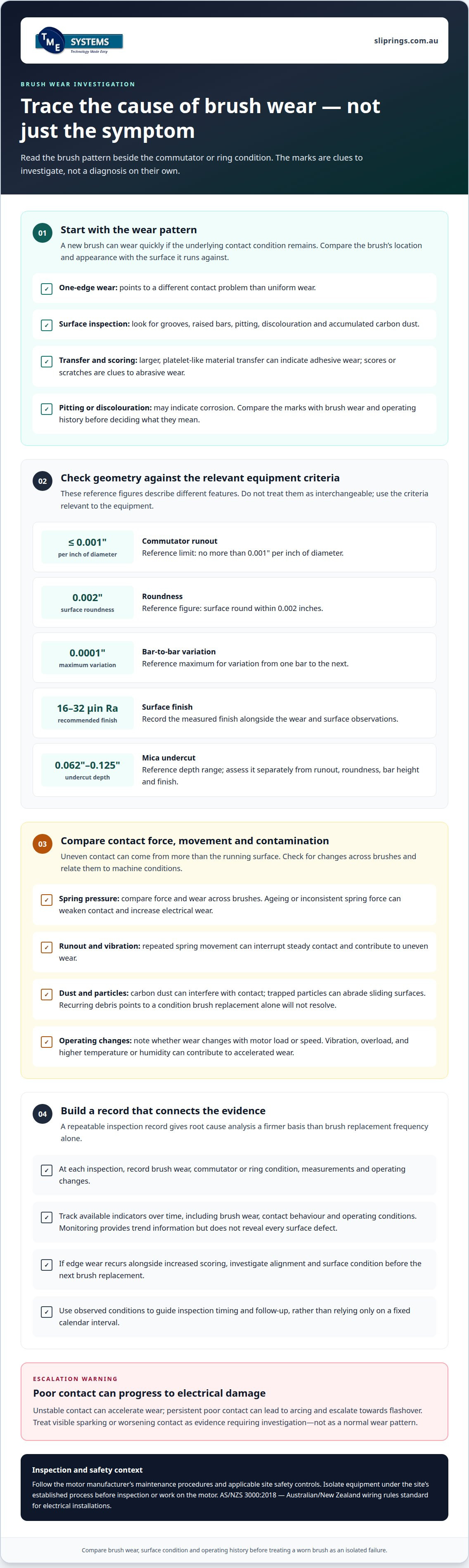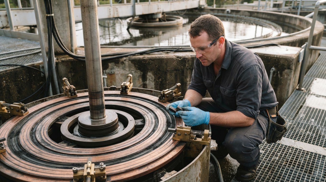
A new set of brushes can wear quickly when the fault lies elsewhere in the machine. Root cause analysis for premature brush wear traces the evidence to likely causes, including a rough or uneven contact surface, inconsistent spring pressure, runout or contamination. Replacing brushes without addressing the underlying condition can leave the wear pattern unchanged.
Brush wear is a useful symptom, but it does not identify the fault by itself. The wear pattern and the condition of the commutator or ring can help distinguish mechanical contact problems from electrical or environmental causes.
This article explains how surface condition, spring pressure and runout contribute to wear, and how to interpret these signs during a systematic investigation. You’ll also learn how to build an event timeline, connect operating changes to brush condition and recognise when poor contact may be progressing towards flashover. The aim is to identify the cause before it leads to further damage, rather than treating each worn brush as an isolated failure.
Key Takeaways
- Read brush wear patterns alongside commutator or ring surface condition to distinguish likely mechanical, electrical and contamination-related causes.
- Compare spring pressure across brushes; uneven force can produce uneven wear and weaken contact.
- Consider runout as a source of repeated spring movement and inconsistent brush contact.
- Build a chronological fault timeline to connect changes in operation with wear symptoms and narrow down the underlying cause.
- Trace poor contact early, as unchecked wear can progress to more serious damage, including flashover.
Commutator and ring surface condition
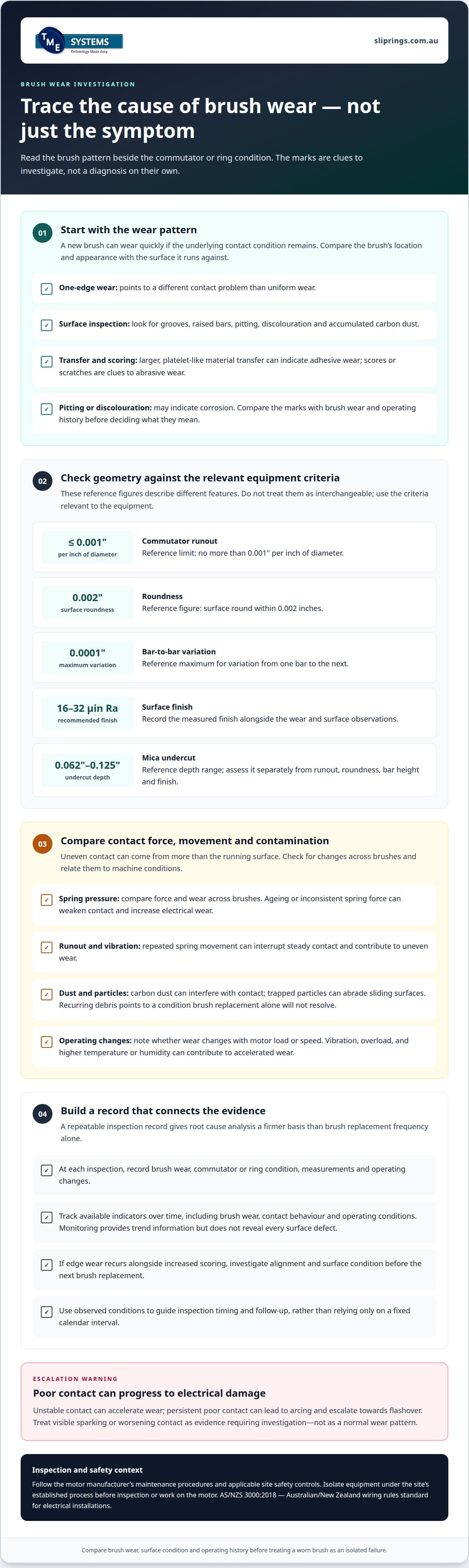
A carbon brush needs a stable contact surface to transfer current. Roughness, scoring, contamination or out-of-round geometry can interrupt contact and accelerate mechanical and electrical wear. Record the wear pattern alongside the commutator or ring condition. For example, a brush worn on one edge points to a different contact problem than uniform wear.
Inspect the commutator for grooves, raised bars, pitting, discolouration and accumulated carbon dust. Adhesive wear can leave larger, platelet-like material transfers between parts, while abrasive wear often produces scores or scratches. Pitting or discolouration may indicate corrosion. These marks are clues, not a diagnosis on their own, so compare their location with brush wear and the machine’s operating history.
Measurements help distinguish visible damage from geometry problems. Reference figures include commutator runout of no more than 0.001" per inch of diameter, a surface round within .002 inches, and maximum bar-to-bar variation of 0.0001". A recommended surface finish is 16-32 μin Ra, while mica undercut depth is specified at 0.062"-0.125". Apply the relevant equipment criteria rather than treating these figures as interchangeable: runout, roundness, bar height, finish and undercut describe different features.
For Australian electrical installations, AS/NZS 3000:2018 - Australian/New Zealand wiring rules standard for electrical installations. Brush inspection and replacement also need to follow the motor manufacturer’s maintenance procedures and applicable site safety controls. Isolate equipment under the site’s established process before inspection or work on the motor.
Online brush condition monitoring can provide trend information between planned inspections. Track available indicators, such as brush wear, contact behaviour and operating conditions, over time. If one motor’s readings change alongside a new wear pattern, record when the change began and compare it with maintenance or operating events. Monitoring supports diagnosis, but does not directly reveal every surface defect.
Condition-based maintenance uses observed conditions to guide inspection timing and follow-up, rather than relying only on a fixed calendar interval. A practical record pairs wear observations from each inspection with commutator measurements and operating changes. For example, recurring edge wear with increased scoring calls for attention to alignment and surface condition before the next brush replacement. This gives root cause analysis for premature brush wear a firmer basis than replacement frequency alone.
That evidence can make follow-up inspections more useful. An uneven commutator contact surface can accelerate carbon brush wear, so consider a change in brush condition alongside surface observations, not in isolation. Record the location and appearance of any transfer or marking. Comparing inspections can show whether a pattern persisted or changed alongside operating conditions.
Adhesive wear can be identified by larger, platelet-like chunks of material transferred from one machine part to another. Abrasive wear can be identified by scores or marks on machine parts, including excessive scratches and cuts on failed discs. Consider these visible clues alongside measured geometry and recorded brush wear when deciding what to inspect next. If the evidence does not align, retain that uncertainty and seek further inspection before treating a single mark as a confirmed cause.
Degradation progression from poor contact to flashover
Poor contact can trigger a gradual cycle: unstable current transfer accelerates wear, while debris or vibration can further disrupt contact. Understanding how these conditions interact helps distinguish an early warning from a developing electrical fault.
Carbon Dust and Particulate Contamination
Carbon dust and other particles can build up around the brush and commutator, interfering with the contact interface. Contamination can prevent proper brush contact and reduce current density at the contact point. A particle trapped between sliding surfaces may also abrade them, leaving scratches or cuts. Compare dust accumulation with brush wear and contact condition. Recurring debris points to a condition that brush replacement alone won’t resolve. Periodically removing accumulated dust with compressed air can help promote more even wear.
Vibration and Intermittent Contact
Brush vibration is repeated movement that interrupts steady contact with the rotating surface. Each separation and return can cause uneven current transfer, local heating and further wear. Current density rises when the same current passes through a smaller contact area, while overload adds electrical and thermal stress. Vibration disrupts contact, and higher temperature and humidity can contribute to accelerated wear—an effect frequently observed on heavy-duty equipment like vibratory and aggregate screens from Compass Wire Cloth Corporation, where mechanical oscillation is continuous.
Relate vibration to operating conditions. For example, note whether wear changes when a motor’s load or speed changes. Intermittent contact can produce arcing; if poor contact persists, electrical damage can escalate towards flashover. Treat visible sparking or worsening contact as evidence that requires investigation, not as a normal wear pattern.
Spring Ageing and Inconsistent Contact
A brush spring maintains force against the commutator or ring, but springs fatigue over time. Reduced or inconsistent force can make brush contact unstable, increasing electrical wear. Clock and finger style springs can lose force as the brush wears, so a fit that was initially acceptable may change during service. Compare contact and wear patterns across brushes. Differences may point to inconsistent spring action rather than a uniform operating condition.
Brush-Slip Ring Contact and Patina
Patina is the thin contact film that develops on a brush-running surface during operation. A stable film supports consistent brush contact, while a damaged or contaminated film can disrupt current transfer. Inspect the ring alongside the brush: patchy discolouration, deposits or signs of arcing can show whether the interface is deteriorating. Don’t treat every colour change as a fault; relate its appearance to contact stability and the machine’s operating history.
For new carbon brushes, the recommended bedding-in method is to run the motor at 25% speed for 2-4 hours. Record the operating conditions and subsequent wear pattern, so changes can be compared during maintenance.
Unequal spring pressure and brush wear
Brushes need consistent pressure and alignment to maintain contact as the commutator rotates. Comparing wear across brushes can reveal whether force, positioning or brush material is contributing to accelerated wear.
Spring Pressure and Uneven Wear
Spring pressure is the force that holds a brush against the rotating contact surface. Inadequate pressure can cause rapid electrical brush wear, while unequal force can leave brushes wearing at different rates. For the applications described, a recommended brush pressure is 2-4 psi; compare readings between brush positions and with the motor’s applicable requirements.
Low pressure can make contact unstable, while excessive pressure can increase friction and mechanical wear. Clock and finger style springs tend to lose force as the brush wears, so pressure can change during service. For example, if brushes on one side wear faster, compare their spring force and contact patterns with those at the remaining positions before replacing the full set.
Brush grade, hardness and material also affect wear. A grade unsuited to the motor’s current, speed or contact conditions may wear too quickly or fail to maintain a suitable contact film. Confirm that the installed grade matches the motor application, then compare the removed brush’s wear pattern with the operating conditions.
Alignment and Holder Clearance Checks
Alignment and holder clearance determine whether each brush can move freely and meet the commutator squarely. Inspect brush seating, holder position and freedom of movement, then compare holder alignment across positions. Misalignment greater than 0.5° can cause uneven wear, and incorrectly installed holders can damage the contact surface.
Measure holder clearance during troubleshooting; the recommended range is 0.002"-0.004". Clearance that is too tight can restrict brush movement, while excessive clearance can allow instability. Correct holder positioning and clearance to the equipment’s applicable requirements, then recheck that the brush travels freely without binding.
Assess spring pressure with a suitable pressure measurement at the brush face, using the same method across positions. Compare each result with the recommended 2-4 psi range for the applications described. If force differs, inspect the spring condition and seating before adjusting or replacing components. Recheck wear distribution after the correction.
Keep the findings together: brush grade, measured pressure, holder clearance, alignment and wear location. For example, edge wear on one brush alongside a misaligned holder suggests a different cause from uniform wear across the brushes. This comparison helps distinguish a material mismatch from spring or installation faults.
Regular checks of spring pressure can help prevent uneven carbon brush wear. Include pressure readings for each brush position in routine inspections, using the same measurement method so differences are easy to compare. Consider the readings alongside wear patterns, holder clearance and alignment. If a reading differs, inspect the spring and its seating before deciding on a correction, then check the pressure again. Tracking results alongside wear distribution provides a consistent way to spot changes as brushes wear and assess pressure with the other conditions being checked.
Out-of-round commutators or rings
An out-of-round commutator or ring changes the contact gap as it rotates. The brush follows the changing profile, making its spring flex repeatedly instead of holding a steady position. This links geometric error with brush movement, spring fatigue and inconsistent contact. The effect can occur even when the surface looks smooth during a stationary inspection.
Assess geometry separately from surface finish. A polished track can still be eccentric, while a round surface can have grooves or contamination. Measure runout around the rotating face with suitable equipment, and record the reading against the angular position. Compare the result with the equipment’s specified tolerance. Commutator and slip-ring limits may differ, so don’t apply a criterion to another assembly without checking that it is appropriate.
Look for a repeating pattern. If the brush lifts or loses contact at the same rotational position, compare that event with the measured high point. A change in wear around the circumference can also indicate that the brush meets a varying surface. By contrast, wear concentrated at one edge may point to alignment or holder issues. These observations help distinguish geometric causes from surface damage.
An out-of-round ring makes the spring flex more often, which can shorten spring life and create a risk of inadequate pressure. As the spring weakens, contact may become less consistent, adding electrical stress to the original mechanical problem. A useful investigation records both ring geometry and spring condition. Replacing a fatigued spring without addressing the ring can leave the recurring movement unresolved.
Check the assembly in a controlled sequence: inspect the ring and mounting, measure runout, then compare brush contact over a rotation. Record the motor’s operating state and measurement position so later readings use the same reference. If the ring is mounted on a shaft, include shaft or mounting movement in the assessment. Otherwise, a reading from the ring alone may not show where the eccentric movement begins.
Distinguish a geometric fault from a changing operating condition. For example, if brush contact varies at one repeatable point while the motor runs steadily, examine the ring’s profile more closely. If the symptom changes with operating conditions, compare those conditions with measurement records before concluding that geometry is responsible. A repeatable pattern supports diagnosis, but does not prove the underlying cause on its own.
Use the findings to guide corrective work on the relevant assembly, then repeat the same measurements and contact observations. A changed runout pattern or more consistent brush tracking provides useful evidence that the intervention addressed the mechanism. Keep the original readings with maintenance records. Comparing them with later brush wear can show whether the fault has returned or shifted.
Systematic root cause analysis
Systematic root cause analysis separates the underlying reasons for brush wear from symptoms such as dust or short brush life. A clear problem statement and chronological timeline help connect wear evidence with operating changes.
A Systematic Investigation
Begin with a precise statement, such as “brush wear increased after a drive change”. Build a timeline of maintenance, load changes, operating interruptions and the first observed wear. Put events in chronological order, then compare the sequence with physical evidence. This helps distinguish a cause that preceded the fault from an event that followed it.
Keep separate records for machine behaviour and maintenance or operator actions. For example, record when wear changed alongside any drive, load or inspection changes. This structure keeps the investigation focused on evidence and makes competing explanations easier to assess.
Reading Brush Wear Patterns
Brush wear patterns are physical evidence that can narrow down the likely fault, but they need context. Uneven wear may direct attention to contact or holder positioning, while scoring can point to abrasive particles or a damaged surface. Compare brushes across positions and relate each pattern to the corresponding contact area.
Don’t treat one mark as proof. Check whether the pattern repeats, then compare it with measurements, operating history and maintenance records. For example, a timeline showing that wear changed after a drive modification gives that event a stronger basis for investigation.
Operating changes deserve particular attention on DC motors. Modern SCR drives can accelerate brush wear to 2-5 times the normal rate. Legacy DC motors designed for smooth motor-generator supply at 120Hz ripple may be incompatible with modern SCR drives operating at 360-720 Hz ripple. A drive change therefore warrants comparison with the motor’s design and the onset of wear.
Use the comparison to test explanations rather than jump to replacement. If the drive stayed unchanged while one brush position developed a distinct pattern, inspect local contact and holder conditions. If several brushes changed after an operating modification, examine shared electrical and operating factors. These are investigation paths, not diagnoses on their own.
Record observations consistently: brush position, wear appearance, commutator or ring condition, operating state and event date. Add a timeline entry whenever maintenance or operating conditions change. The chronology can reveal a sequence such as a drive modification, altered contact behaviour and then accelerated wear, helping separate initiating causes from later effects.
The key is to test each proposed cause against timing and physical evidence. A cause should explain both when the wear began and where it appears. If the evidence does not fit, retain the alternative explanations and gather comparable observations during the next inspection.
TME Systems
TME Systems helps match industrial slip-ring requirements with a suitable product option. When a brush wear investigation points to a rotary electrical connection issue, selection depends on factors such as circuit count, current, voltage, speed, mounting style and operating environment.
Its range includes Mercotac Slip Rings, Meridian Laboratory Slip Rings, BGB Innovation Slip Rings and Prosper Rotation Slip Rings. Sharing the application requirements and observed symptoms can help focus the discussion on the relevant product category and technical fit. This is a useful next step when the investigation indicates that the existing rotary connection may not suit the application.
Contact TME Systems to discuss your slip ring application.
Turn the findings into a better-fit decision
A disciplined root cause analysis for premature brush wear can inform more than the immediate maintenance response. Use the evidence to decide whether the operating baseline needs to change, and define what observation will show whether that change addressed the fault.
Document the decision alongside the supporting evidence and expected change in machine behaviour. This gives maintenance and engineering teams a shared reference for assessing the next inspection, rather than treating each brush replacement as a separate event. Across facilities operating continuous rotary machinery—such as the industrial pallet wrapping systems highlighted by stretch-wrappers.co.uk—routine monitoring and documented servicing keep rotary drives and electrical contacts performing dependably.
With a clear rationale for the corrective decision, your team can move forward with greater confidence and a stronger basis for future maintenance planning.
Frequently Asked Questions
What causes premature wear of carbon brushes in electric motors?
Premature wear occurs when brush and motor operating conditions are poorly matched or change during service. First distinguish whether wear affects every brush or only particular positions. If all brushes change together, examine shared changes in duty or electrical operation; if one differs, focus the investigation on that position. Keep the removed brushes as a labelled set to preserve this comparison.
How do commutator or slip-ring condition, runout and surface finish affect brush life?
These factors affect how consistently a brush runs against the rotating contact track. To make inspection records comparable, assess the same track locations and use the same measurement method each time. Note whether a visible mark follows the direction of rotation or remains local to one area. This distinction helps describe the contact evidence clearly without treating surface appearance alone as a complete diagnosis.
What measurements and inspection steps are used to diagnose premature motor brush wear?
Start with the motor’s maintenance history and the brush manufacturer’s or motor documentation, then record the observed condition against the relevant equipment criteria. Preserve removed brushes in labelled pairs or sets, noting their original positions and orientation. This allows later reviews to compare wear distribution without relying on memory. Keep the inspection record with the motor’s maintenance history so the next assessment can use the same reference.