The most capable rotary connector is not automatically the right one for a solar tracker. A rotary connector for a solar tracking array should match the drive system’s electrical paths, load, speed and mounting arrangement. Selection also depends on the installation environment and the project’s operating requirements.
Energy capture is an important factor when comparing tracker designs, but the rotary electrical connection also needs to suit its role. A mismatch in circuit count, current or installation space can make it harder to integrate the connector with the drive and control equipment.
This article compares conventional slip rings, collector rings and liquid-metal options, and explains how mounting style and operating conditions affect selection. It also outlines how to assess the connector’s role in the wider tracker system, its operating demands and long-term requirements. Use these criteria to narrow the options to those that suit your array and drive configuration.
Key Takeaways
- Match the connector type to the tracker’s drive arrangement and the electrical paths that need to cross the rotating interface.
- Compare slip rings, cable loops and rotary joints by how each handles continuous movement, wiring layout and system integration.
- Set electrical and signal requirements alongside rotation and speed demands to narrow down suitable connector options.
- Assess project economics in the context of the full tracker system, including its operating requirements and expected use.
- Use application engineering support to align mounting style and connector selection with the array’s technical requirements.
What types of rotary connectors are suitable for solar tracker systems?
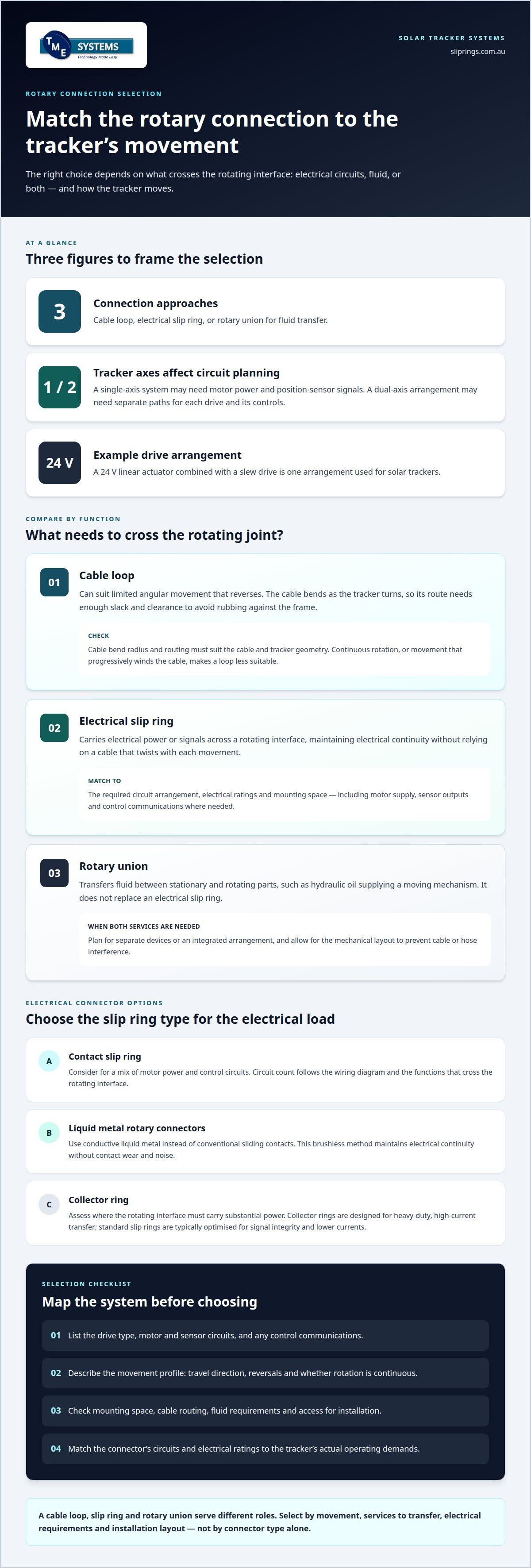
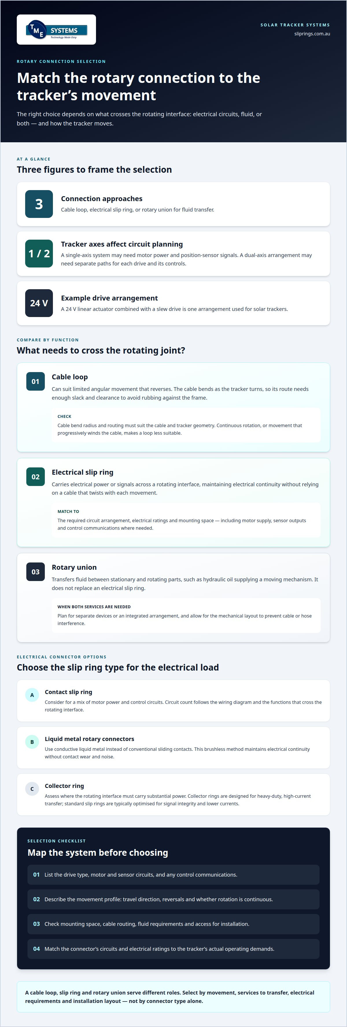
The right connector depends on the tracker’s drive design and the circuits that cross its rotating interface. A single-axis system may need to transfer motor power and position-sensor signals between stationary and moving sections. A dual-axis arrangement may need separate electrical paths for each drive and its controls. Map those functions first, then match the connector to the required power, signals and movement.
Conventional contact slip rings transfer electrical power and signals through sliding contacts as connected parts rotate. They can suit a tracker whose motors and sensors need continuous connections during panel movement. The circuit count depends on the wiring diagram: motor supply, sensor outputs and control communications may each need dedicated paths. This makes a contact slip ring a practical starting point when selecting a rotary connector for a solar tracking array.
Liquid-metal rotary connectors use conductive liquid metal instead of conventional sliding contacts. This brushless method maintains electrical continuity without contact wear and noise. It may suit designs where those characteristics matter, but selection still depends on the required circuits, electrical load and signal type. Match the connector to the tracker’s operating conditions, not just its contact technology.
Collector rings are another category to consider when the rotating interface carries substantial power. The distinction between a collector ring and a slip ring is their intended emphasis: collector rings are designed for heavy-duty, high-current transfer, while standard slip rings are typically optimised for signal integrity and lower currents. For a tracker, the choice depends on the actual drive and auxiliary loads. A high-current design is unnecessary if the interface carries only control signals.
- Contact slip ring: consider for a mix of motor power and control circuits.
- Liquid metal rotary connector: consider where brushless contact technology suits the operating brief.
- Collector ring: assess where the rotating interface must carry high current.
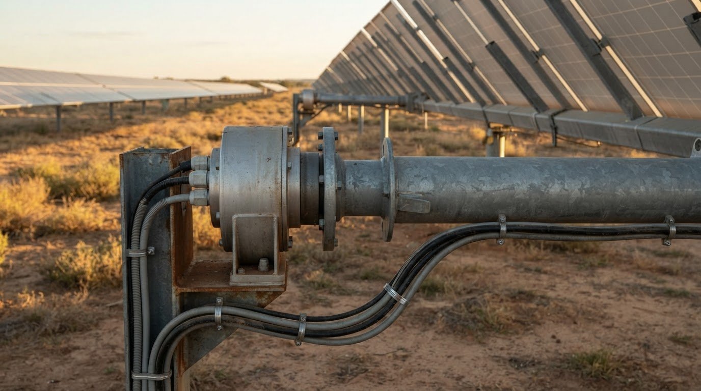
Mounting style further narrows the options. A through-bore slip ring fits over a rotating shaft and can leave space for auxiliary components. An end-of-shaft unit may suit a drive that does not need a central shaft opening. The tracker’s mechanical layout, available clearance and cable entry points determine which arrangement will integrate cleanly.
Finally, treat the connector as part of the complete drive system. Solar trackers use motors and sensors to adjust panel position as light conditions change, so the rotary interface must accommodate the circuits serving those functions. A 24 V linear actuator combined with a slew drive is one drive arrangement used for solar trackers. Specify the drive type, movement, circuit functions and installation layout before selecting a connector category.
How do slip rings compare with cable loops and rotary joints for solar trackers?
The key difference between these options is how they handle movement and what they transfer. A slip ring carries electrical power or signals across a rotating interface. A cable loop keeps conductors physically connected, while a rotary union transfers fluids such as hydraulic oil. Choose based on the tracker’s movement and the services that need to cross its rotating joint.
A cable loop can suit a tracker that moves through a limited angle and then reverses. The cable bends as the structure turns, so its route needs enough slack and clearance to avoid rubbing against the frame. The bend radius and cable path must suit both the cable and tracker geometry. A single-axis tracker with controlled back-and-forth movement may work with a loop. Continuous rotation, or a layout that progressively winds the cable, makes a loop less suitable.
A slip ring maintains electrical continuity as connected sections rotate. It avoids relying on a cable that twists with each movement, which can simplify routing when electrical circuits cross the rotating interface. The trade-offs are the need for suitable mounting space and electrical ratings, plus another component to integrate into the system. For a tracker carrying motor supply and sensor signals across a rotating axis, match the slip ring’s circuit arrangement to those functions.
A rotary joint, also called a rotary union in fluid-transfer applications, serves a different purpose. It passes fluid between stationary and rotating parts, such as through a hydraulic line supplying a moving mechanism. It does not replace an electrical slip ring. If a tracker needs both hydraulic power and electrical signals across the same axis, plan for separate devices or an integrated arrangement. The mechanical layout must accommodate both and prevent cable or hose interference.
- Choose a cable loop for controlled angular movement with a safe, clear cable route.
- Choose a slip ring when electrical circuits must remain connected through rotation.
- Choose a rotary union when fluid must cross between stationary and rotating sections.
Compare options against the full movement profile, not just the drive motor. Include travel direction, reversals, cable routing, fluid requirements and mounting access. A rotating tracker assembly might use a slip ring for sensor and motor circuits alongside a separate rotary union for hydraulics. A cable loop may be simpler where movement is restricted and cable flex can be managed.
For projects that require a dependable rotary connector for solar tracking array applications, available options from TME Systems Pty Ltd can be assessed against your specific electrical and mechanical requirements.
What voltage, current, signal, and rotation ratings are needed for a solar tracker rotary connector?
Set ratings from the tracker’s electrical schedule and movement profile, not from a generic connector category. Start with the drive motor, sensors, controller and any communications crossing the rotating interface. A 24 V linear actuator combined with a slew drive is one solar-tracker arrangement. Its actuator supply is only one part of the specification; the sensor and control circuits also need suitable paths.
For voltage, record the operating voltage of each circuit and distinguish power from signal lines. The connector’s electrical rating must suit the connected circuit, while insulation between separate paths must suit the system design. Do not assume that the 24 V actuator example defines every tracker’s voltage requirement. A different motor, controller or auxiliary device changes the electrical schedule and can change the connector specification.
Start current selection with the load on each power circuit. Record the motor’s normal operating current and the higher demand when starting or changing position. Then account for how many circuits may carry current simultaneously. Circuit count affects connector configuration, while each path’s current rating must suit its load. Consider heat management too: current generates heat inside the assembly, and ambient conditions and enclosure layout affect heat dissipation.
Assess signal circuits separately. A tracker may carry encoder feedback, limit-switch states and control communications across the rotating interface. These signals have different sensitivities and transmission requirements. List each signal type, its electrical characteristics and whether it operates alongside motor power. Separating power and signal circuits can help manage electrical interference. For Ethernet or other high-speed data, choose an interface designed for that signal rather than assuming any slip ring will carry it reliably.
Describe rotation by how the tracker moves and how quickly. Record whether the axis turns continuously, reverses through a limited arc or makes occasional positioning movements. The connector’s rotational speed rating must suit the mechanism’s operating speed. Also consider the direction and frequency of reversals, which describe the real movement profile more accurately than a single maximum-speed figure.
- Voltage: document each motor, sensor and control circuit separately.
- Current: include operating and starting demand for each power path.
- Signals: identify feedback, switching and communications requirements.
- Rotation: specify direction, travel pattern and rotational speed rating.
Bring these details together in one interface schedule. For example, a tracker with a 24 V actuator, encoder feedback and controller communications needs distinct power and signal requirements, plus a movement profile for its rotating axis. That schedule gives engineers a sound basis for assessing connector ratings and configuration.
How many rotations and what rotational speed must a solar tracker connector support
The connector must match movement at its mounting point, not simply the motor’s nameplate speed. A solar panel axis may move through a limited arc, reverse direction and pause as the controller adjusts the array. That differs from continuous rotation. Define the movement pattern first, then establish the connector’s required rotational speed rating and operating life.
Count rotation as accumulated angular travel rather than assuming each tracking movement equals a full turn. For example, a tracker that moves east and then returns west makes two movements but may not complete a full revolution. Estimate total turns by adding the absolute angular travel over the operating schedule and dividing by a full circle. Include movement in both directions: opposite movements still contribute to contact travel and mechanical duty.
For a single-axis tracker, assess the full daily tracking path and return movement. For a dual-axis system, do this for each rotating axis, since horizontal and vertical movement can differ. Include additional positioning movements from the control strategy. Software can model seasonal changes in the sun’s position, so the commanded path may vary through the year. Use that operating profile to estimate accumulated rotation over the intended service period.
Calculate speed separately. The rotational speed rating is the connector’s maximum permissible revolutions per minute (RPM). Compare it with the speed at the connector shaft, not the motor shaft, because gears or a slew drive may reduce output speed. If the tracker uses a linear actuator, its travel rate alone does not define connector RPM. Convert the resulting axis movement into angular speed at the connector.
- Movement: record each axis’s travel direction, angle and reversal pattern.
- Rotation count: total the angular travel in both directions, then convert it to turns.
- Speed: calculate movement at the connector after gearing or drive conversion.
- Duty: include positioning, pauses and any commanded return movement.
Repeated starts and reversals matter as well as peak RPM. Even within its speed rating, a connector may experience frequent direction changes or extended operation. Record how often the tracker moves, how long each movement lasts and whether both axes operate together. These details describe the connector’s actual duty more accurately than a single maximum-speed figure.
Finally, compare the calculated movement profile with the connector’s rotation and speed limits as separate requirements. A low-speed tracker can still accumulate substantial total travel over years of operation. Conversely, a high motor speed does not necessarily mean high connector speed if the drive reduces rotation. This distinction helps specify a connector for the tracker’s real motion profile.
What are typical prices for solar tracker slip rings in Australia
For an Australian solar tracker project, assess the connector as a specified assembly, not a generic part. Two slip rings may look similar yet serve different electrical and mechanical duties. Start with the tracker’s circuit schedule, movement profile and mounting drawing. These details explain why product selections vary between projects and why each tracker needs its own application assessment.
Start with the electrical scope. Record each circuit’s function, operating voltage and current, then distinguish motor power from sensor and communications signals. For example, an actuator supply and encoder feedback have different requirements. Note the circuit count and which paths operate simultaneously. This information helps define the connector configuration, including whether separate power and signal paths are needed.
Next, describe the tracker’s movement. A single-axis tracker that reverses through a limited arc has a different duty from an assembly with continuous rotation. Document direction, angular travel, rotational speed rating and expected operating pattern. For dual-axis equipment, assess each axis independently. Without this information, a connector may be unsuitable even when its electrical connections appear to match.
Mechanical integration also shapes the specification. Include the shaft arrangement, available installation space, cable entry direction and required mounting style. A through-bore slip ring fits over a rotating shaft, while an end-of-shaft format suits a different layout. The tracker drawing should show nearby components, including hydraulic lines and drive hardware. Clearances and access affect which assembly can be integrated.
Include environmental conditions in the application brief. Describe exposure to dust, water, heat and vibration at the installation point. The IP rating, enclosure arrangement and thermal management requirements should reflect the actual location and system design. “Outdoor use” alone is not a complete environmental specification: a dry inland installation may face different conditions from one near the coast.
Use a consistent comparison checklist for each proposed configuration:
- Electrical: circuit count, voltage, current and signal type.
- Movement: rotation pattern, speed and axis arrangement.
- Mechanical: shaft geometry, mounting and available clearance.
- Environment: ingress protection and operating conditions.
- Project scope: interfaces, documentation and integration requirements.
Compare options only after applying the same actuator, encoder, mounting and environmental requirements to each. If one proposal includes a custom mounting arrangement or additional signal paths, record the difference explicitly. A like-for-like technical scope gives the project team a sound basis for evaluating alternatives and selecting a connector that fits the tracker design.
Price comparisons can be considered alongside expected energy output, while keeping the connector specification tied to the project’s electrical, movement and mounting requirements. Dual-axis solar trackers typically increase annual energy production by 25 to 45% over fixed mounting. Single-axis solar trackers typically increase annual energy production by 15 to 25% over fixed mounting at most US latitudes.
Solar trackers can increase energy output compared with fixed panels, though the gain varies by system and location. The page estimates annual generation of 1826 kWh for a 1 kW dual-axis solar tracking system in Sydney, Australia, and 1460 kWh for a 1 kW fixed flat-panel system in Sydney, Australia.
TME Systems
TME Systems helps assess slip ring options against a solar tracker’s electrical, mechanical and environmental requirements. Its technical application consulting can help narrow the choice using factors such as circuit count, current, voltage, speed, mounting style and site conditions.
This support is useful when the drive and control requirements are defined but the connector configuration still needs to be matched. TME Systems supplies Mercotac, Meridian Laboratory, BGB Innovation and Prosper Rotation slip rings, allowing you to consider different connector technologies without assuming one type suits every array.
Share your tracker’s operating requirements with TME Systems to discuss a suitable rotary connector approach.
Set the connector scope before finalising the tracker design
Include the rotary connector in the tracker design process while the drive layout and electrical interfaces are being coordinated. This gives the project team an opportunity to resolve fit, wiring and integration questions before they constrain the finished assembly. Select a rotary connector for a solar tracking array as part of the system architecture, not as an isolated component.
TME Systems’ technical application consulting can help match tracker requirements to suitable slip ring options. Its range includes Mercotac Slip Rings, Meridian Laboratory Slip Rings and BGB Innovation Slip Rings. Discuss your project’s interface requirements with TME Systems to determine how they shape connector selection.
Contact TME Systems to discuss your project, and take the next step towards a connector specification that fits your tracker design.
Frequently Asked Questions
What is a rotary electrical connector for a solar tracking array?
A rotary connector is an electrical interface that keeps circuits connected between stationary and rotating parts of a tracker. For example, it can maintain the electrical connection between a fixed control cabinet and equipment on a moving panel support as the array changes position. Its circuit design and mounting must suit the specific tracker system.
What are the main failure risks and maintenance requirements for solar tracker rotary connectors?
Risks include mismatched circuit or current ratings, inadequate heat dissipation, and poor mounting or cable routing. A cable loop can rub against the frame if its route lacks clearance. The article gives no specific maintenance schedule for rotary connectors, but recommends regular tracker drive and bearing inspections, checking slewing-drive oil and fasteners each season, and annual tracker-angle calibration.