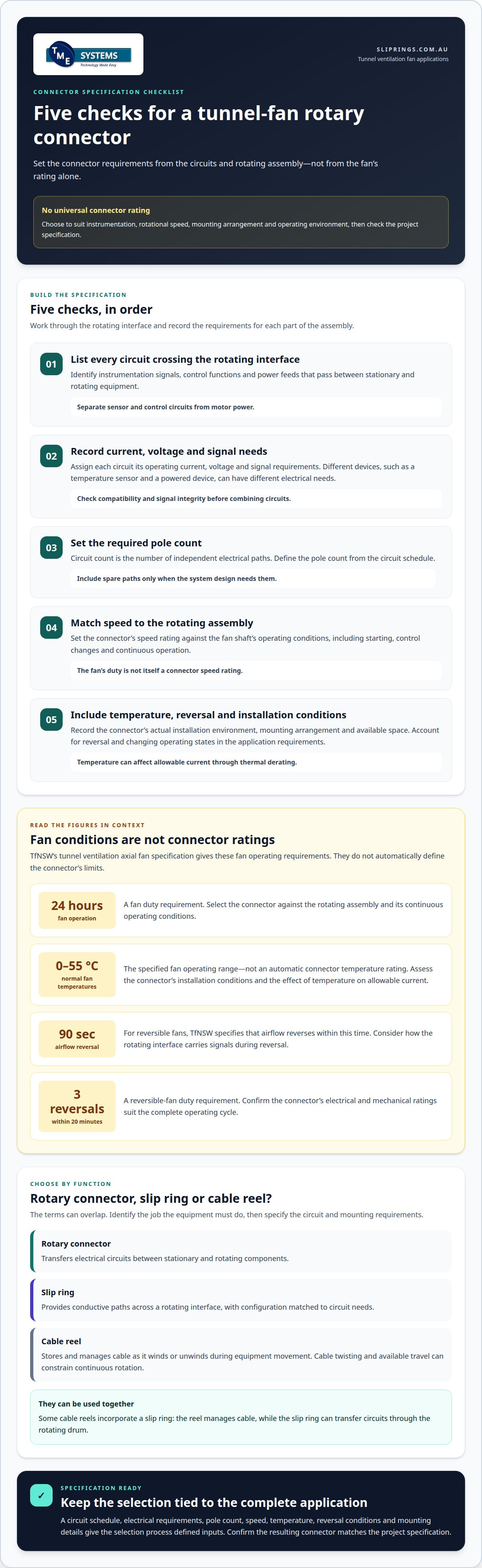
There is no universal rating for a rotary connector for a tunnel ventilation fan. Choose one to suit the instrumentation circuits’ electrical requirements, the fan’s rotational speed, the mounting arrangement and the operating environment. Then confirm that it matches the project specification.
That distinction matters: a fan’s operating requirements don’t automatically define the connector’s limits. For example, TfNSW’s tunnel ventilation axial fan specification calls for 24-hour operation and normal operating temperatures from 0 to 55 °C. These are fan conditions, not a connector rating.
A rotary electrical connector transfers power, signals or data between stationary and rotating equipment. Circuit count, current and voltage help determine whether it suits the instrumentation. Assess those requirements alongside rotational speed, environmental conditions and mounting space. Liquid metal rotary connectors may suit some applications, while smoke-control duties can affect the wider project specification. Keep the connector requirements distinct from the fan’s performance criteria.
Key Takeaways
- Match the connector’s circuit count, current, voltage and speed rating to the instrumentation and fan assembly.
- Understand when a slip ring provides a suitable rotating electrical connection, and how that differs from a cable reel.
- Account for smoke-control requirements in the project specification, including the relevance of EN 12101-3.
- Define mounting, environmental and electrical requirements together to guide connector selection.
- Plan installation and maintenance around the connector’s configuration and operating conditions.
What current, voltage, pole count and speed ratings are required?
Current rating is the allowable electrical load for a connector circuit. Voltage rating is the electrical potential the circuit is designed to carry. For tunnel-fan instrumentation, assess sensor and control circuits separately from motor power. The connector’s duty depends on the circuits crossing the rotating interface, not simply the fan motor’s rating. A temperature sensor and a powered device, for example, may have different electrical requirements.
Circuit count is the number of independent electrical paths available through the connector. Pole count describes those conductive paths in the selected configuration. Identify which instrumentation signals, control functions and power feeds must cross between stationary and rotating equipment. Assign each circuit its operating current and voltage, and include spare paths only when the system design needs them. Combining unrelated signals without checking their electrical characteristics can compromise signal integrity.
Speed rating is the maximum rotational speed at which a connector is designed to operate. Match it to the fan shaft’s operating speed and any changes during starting or control. TfNSW’s tunnel ventilation axial fan specification calls for fans suitable for 24-hour operation. That is a fan duty requirement, not a connector speed rating. The connector must be selected against the actual rotating assembly conditions, including continuous operation.
Environmental temperature also affects electrical selection. TfNSW specifies normal fan operating temperatures from 0 to 55 °C. This range describes the fan specification; connector performance must be assessed for its own installation conditions. Temperature can affect allowable current through thermal derating, which reduces the permitted load as ambient temperature rises. Consider enclosure conditions and heat from nearby equipment alongside circuit current. Don’t treat the fan’s temperature range as an automatic connector rating.
Reversible fans add operating demands that should inform system design. TfNSW requires reversible tunnel ventilation axial fans to reverse airflow within 90 seconds and support three flow reversals during a 20-minute period. These requirements describe fan operation, not a universal connector specification. They make it essential to consider how the rotating interface carries instrumentation signals during reversal and changing operating states. Confirm that the connector’s electrical and mechanical ratings suit the complete duty cycle.
Use this sequence to prepare a connector specification:
- List each signal and power circuit crossing the rotating interface.
- Record each circuit’s current, voltage and signal requirements.
- Define the required pole count from the circuit schedule.
- Match the rotational speed rating to the fan assembly’s operating conditions.
- Include temperature and reversal conditions in the application requirements.
This schedule gives the selection process defined inputs. The required current, voltage, pole count and speed depend on the instrumentation architecture and fan assembly. There is no single rating for every tunnel fan.
How do rotary connectors differ from slip rings and cable reels for fan applications?
A rotary connector transfers electrical circuits between stationary and rotating equipment. “Slip ring” commonly refers to a rotary connector that maintains electrical contact as one side turns. The terms can overlap, so specify the function and requirements rather than relying on labels alone.
For a tunnel fan, start by identifying the rotating boundary. If instrumentation signals must pass between a fixed control system and a rotating fan assembly, a slip ring can provide continuous electrical paths across that interface. Circuit count, signal compatibility and mechanical arrangement determine suitability. Choosing a connector by name alone may not match the required circuit type or mounting configuration.
A cable reel winds and unwinds cable as equipment moves or rotates. It stores cable on a drum, rather than relying solely on a compact contact assembly. Cable reels can suit movement along a defined path or limited rotation. For continuous rotation, cable twisting and available travel become design constraints. Match the arrangement to the fan’s movement, not just its need for electrical continuity.
Some cable reels incorporate a slip ring to maintain electrical connections as the drum turns, so the two are not always alternatives. The reel manages the cable, while the slip ring can transfer circuits through the rotating drum. A travelling assembly may need both cable payout and electrical transfer. A rotating fan instrumentation interface, by contrast, may need a rotary connector without a long cable winding onto a drum.
Compare the options by function:
- Rotary connector: Transfers electrical circuits between stationary and rotating components.
- Slip ring: Provides conductive paths across a rotating interface, with configuration matched to circuit needs.
- Cable reel: Stores and manages a cable as it winds or unwinds during equipment movement.
Signal quality is another selection factor. Instrumentation may carry low-level measurements alongside control circuits, making circuit separation and electrical compatibility important. A reel’s stored cable also requires physical routing and bend space, which a connector-only arrangement may avoid. A rotary connector, however, does not replace cable needed to reach equipment beyond the rotating interface.
Map the fixed and rotating components first. Then identify which circuits cross that boundary, whether rotation is continuous, and whether cable must travel with another moving assembly. Those answers clarify whether a slip ring, a cable reel, or a combined arrangement fits. For application-specific selection, technical application consulting can help align the connector arrangement with the fan system.
Are fire-resistant or smoke-control requirements relevant to tunnel fan connectors in Australia?
Smoke-control duty describes the fan’s role in managing smoke and heat during an incident. A fire-resistant connector is designed to maintain specified functions under defined fire conditions. These terms apply to different parts of the system: don’t treat a fan classification as a connector rating.
In Australia, TfNSW’s specification identifies EN 12101-3 as a standard for powered smoke and heat control ventilators, including fans. This reference concerns the ventilator, not a standalone rotary connector. It does not, by itself, establish a connector’s fire performance or suitability for every tunnel project.
Start with the project’s smoke-control sequence. Identify which fan functions must operate during that sequence, then map the instrumentation and control circuits supporting them. For example, a rotating interface may carry sensor signals needed by the control system. Its required role depends on the project design, not simply the presence of EN 12101-3 in a fan specification.
Separate the system requirements into three groups:
- Fan performance: The duty and operating conditions assigned to the powered ventilator.
- Connector function: The electrical signals and circuits that must cross the rotating interface.
- Fire scenario: The conditions and functions the project requires during smoke-control operation.
This distinction helps prevent a specification gap. A fan may have smoke-control duties, while its instrumentation connector has separate electrical and environmental limits. State the connector’s required function during normal operation and the defined emergency sequence. Include signal continuity, circuit isolation and mechanical arrangement in the interface description.
Fire exposure can affect the equipment around the connector too. Cable insulation, enclosures, seals and mounting components may have project-specific requirements. Consider the rotary joint as part of the complete electrical assembly. Assessing contact technology alone cannot establish how the full installation will behave under fire conditions.
For a practical review, follow these steps:
- Locate the project’s fan and smoke-control requirements, including any EN 12101-3 reference.
- Record which instrumentation signals must remain available during each operating mode.
- Define any connector function specifically required during the emergency sequence.
- Align connector, cable and enclosure requirements with the project design.
The outcome is a clear interface specification, not an assumed certification. TfNSW’s reference to EN 12101-3 helps identify the fan standard in scope; the project documentation must define how the rotary connector fits the required system functions.
Related fan procurement clauses provide useful context, but do not set a rotary connector fire rating. TfNSW’s project-specific requirements schedule lists a 5-year warranty period for tunnel ventilation axial fans. TfNSW’s specification requires a minimum motor efficiency of IEC 60034-30-1 Class IE3 or equivalent, and fan and motor bearings must have a minimum basic rating life (L10) in accordance with ISO 281.
TfNSW also requires the axial fan manufacturer’s quality management system to comply with AS/NZS ISO 9001 and be certified by an appropriately accredited organisation. The fan casing, including all flanges, must be hot-dip galvanised in accordance with AS/NZS 4680, ASTM A123M and/or ISO 1461. Performance curves must be tested in accordance with ISO 5801 and/or ANSI/AMCA 210. These fan requirements should be checked alongside, not substituted for, project-defined connector functions and fire-scenario needs.
How should a rotary connector be sized and specified for a tunnel ventilation fan
Connector sizing means matching electrical and mechanical ratings to the rotating assembly. Start with the instrumentation design and fan interface, not connector dimensions alone. A circuit schedule records each electrical path and its function. Use it to identify signal type, current, voltage, isolation needs and spare circuits. Keep sensor, control and power requirements distinct where their electrical characteristics differ.
A mounting envelope is the space and geometry available for installing the connector. Record the shaft arrangement, attachment points, cable-entry direction and clearance around nearby components. These details determine whether an end-mounted or through-bore slip ring fits. Note the connector’s position relative to the rotating and stationary structures. Incorrectly assessing cable routes or service access can make an electrically suitable unit difficult to integrate.
IP rating - A standard that defines the level of protection against dust and water ingress for electrical equipment. Specify the exposure where the connector will be installed, including tunnel dust, moisture and cleaning conditions. The required rating depends on that environment and the enclosure arrangement. Don’t assume the fan’s enclosure rating also applies to the connector. Document any seals, covers or cable glands that form part of the installed assembly.
Thermal derating reduces allowable current as ambient temperature rises, helping prevent overheating. Include installation temperature and nearby heat sources when assessing current capacity. The connector’s rating must suit its operating conditions, not just the circuit’s nominal load. Also specify the rotational speed rating, which defines the maximum permissible operating speed. Match it to the fan assembly’s mechanical duty and expected operating modes.
Project life requirements help frame the selection, but they do not become connector guarantees. TfNSW’s project-specific requirements schedule lists a 25-year design life and a five-year warranty period for tunnel ventilation axial fans. Those figures apply to the fans, not automatically to their connectors. The connector specification should separately state required service conditions, inspection provisions and the project’s acceptance criteria.
Assemble the specification in a consistent sequence:
- Describe every circuit, its function and its electrical characteristics.
- Set mounting geometry, cable routing and clearance requirements.
- Record the operating environment and required IP rating.
- State rotational speed, thermal conditions and relevant operating modes.
- Define connector performance, documentation and interface acceptance requirements.
For Australian electrical installations, use AS/NZS 3000:2018 - Australian/New Zealand wiring rules standard for electrical installations as the wiring-rules reference within the project design. The final specification should distinguish connector ratings from fan requirements, then capture both in the interface documentation.
What are the installation and maintenance steps for a fan rotary connector
Installation means securing and connecting the rotary connector to the fan assembly. Start by matching the connector identification, drawings and terminal layout to the approved system design. Confirm which section is stationary and which rotates. This helps prevent mounting the connector across the wrong interface or routing cables towards moving parts.
Alignment positions the connector’s rotating and stationary components according to their specified mechanical arrangement. Check shaft fit, mounting faces, clearances and cable entry before fastening the unit. For example, a through-bore design must fit the shaft arrangement without interference. Don’t use the connector to compensate for misalignment in the fan assembly. Follow the connector’s installation instructions for mounting and fastening.
Electrical termination connects each cable conductor to its assigned terminal. Use the circuit schedule and wiring diagram to connect instrumentation, control and power paths correctly. Preserve specified polarity, shielding and separation between circuits. Secure cable entries so movement or vibration doesn’t pull on the terminals. Suitably qualified personnel should complete electrical work under the project’s safe work procedures.
Commissioning checks confirm correct operation after installation. Before energising, inspect fastening, cable routing and terminal connections against the drawings. With the assembly in its intended operating state, test circuit continuity and signal behaviour across the stationary-to-rotating interface. Compare results with the project acceptance criteria and connector documentation. Record any deviations before the fan enters service.
Maintenance is the planned inspection and care of the installed connector during operation. Use the manufacturer’s maintenance instructions and the tunnel maintenance plan to define inspection tasks. The appropriate schedule depends on operating conditions, connector design and exposure to dust or moisture. Don’t assume every contact technology needs the same service method.
Inspection records document the connector’s condition and maintenance performed. At each planned inspection, review mounting security, cable condition, terminal integrity and visible contamination. Note changes in signal behaviour, unusual noise or temperature. Compare observations with commissioning records to identify changes over time, and keep findings with the fan’s equipment records.
A controlled maintenance sequence can include these steps:
- Isolate the relevant equipment under the site’s established safety procedure.
- Inspect mounting, cable routing, enclosures and terminations for visible changes.
- Clean or service the connector only as its manufacturer directs.
- Test the affected circuits against project criteria before returning equipment to service.
- Record inspection results, corrective work and any observed operating changes.
For a tunnel fan, consistent records link installation checks with later condition assessments. Use the drawings, connector instructions and site procedures to guide each task, rather than relying on a generic maintenance interval or method.
TME Systems Pty Ltd
TME Systems Pty Ltd helps assess slip ring options for tunnel-fan instrumentation against project electrical and mechanical requirements. Selection can account for circuit count, current, voltage, rotational speed, mounting arrangement and environmental conditions. Its range includes Mercotac Slip Rings, Meridian Laboratory Slip Rings, BGB Innovation Slip Rings and Prosper Rotation Slip Rings. This support is useful when defining a new rotating interface, reviewing a specification or resolving fit and compatibility questions before procurement. Share the circuit schedule, fan interface details and operating conditions to support a practical assessment. The aim is to match the connector to the application, not assume one configuration suits every fan. Contact TME Systems Pty Ltd to discuss your tunnel-fan connector requirements.
Set the next project step
Carry the connector decision into the project design handover. Recording its role in the equipment documentation gives procurement, integration and future maintenance teams a shared reference, rather than leaving the reasoning in informal correspondence. For a rotary connector for a tunnel ventilation fan, this traceability helps keep the selected interface aligned with the design intent as the project progresses.
If the application is still being defined, TME Systems can help discuss the selection process and relevant engineering considerations. A conversation at this stage can clarify how the connector decision fits into the project workflow.
Start a discussion with TME Systems about your project and take the next design step with a clearer basis for review.
Frequently Asked Questions
What is a rotary connector for a tunnel ventilation fan?
A rotary connector is used when electrical circuits need to cross between fixed equipment and a rotating part of the fan assembly. It isn’t the fan motor or its controller. For example, if a rotating measurement device needs to send readings to fixed monitoring equipment, a rotary connector can provide the electrical connection. If no circuits cross that boundary, the design may not need one.
Which rotary electrical connectors suit tunnel ventilation fan motors?
First determine whether the motor’s electrical supply must pass through a rotating connection. The fan motor and rotating assembly may be arranged so the motor supply doesn’t cross that boundary. In that case, the connector may serve instrumentation instead. If motor power does cross, select the connector for that circuit’s duty, rather than relying on the motor nameplate alone.
What are common failure risks and troubleshooting issues for rotary connectors?
Potential issues include signal-integrity problems from combining circuits without checking their electrical characteristics, and excessive load if temperature-related derating is overlooked. Check circuit requirements, installation temperature, speed rating, and whether the connector suits continuous operation and reversals.