A radar’s rotating interface must keep power and data moving as the antenna turns. Choosing a rotary connector for a wind profiler radar system starts with what must cross that interface: slip rings carry electrical power and signals, while fibre optic rotary joints maintain an optical data path during rotation. Some systems need one technology; others need both.
That distinction matters in wind profiler installations, where the rotary connection forms part of the wider radar system, not an isolated component. Maritime equipment must also contend with salt water and rough seas, while exposed sites can face harsh weather. Select a connector by considering the data path, electrical requirements, rotation and operating environment together.
This guide explains how fibre optic rotary joints and slip rings support rotating radar systems, what to consider when specifying a rotary electrical joint, and how mounting and connector design affect fit. It also outlines how technical application consulting can help translate system requirements into a suitable configuration.
Key Takeaways
- Identify whether the rotating interface needs to transfer electrical power and signals, optical data, or both before selecting a connector type.
- Match slip ring configuration and mounting to the radar’s electrical requirements, available space and mechanical arrangement.
- Account for exposure to harsh weather and maritime conditions when specifying the complete rotating assembly.
- Include the radar’s RF requirements in the specification, alongside the electrical and mechanical interfaces.
- Plan procurement around the required configuration and project schedule; TME Systems offers slip rings from Prosper Rotation, Mercotac and Meridian Laboratory, plus technical application consulting.
Fibre optic rotary joints and slip rings for radar systems
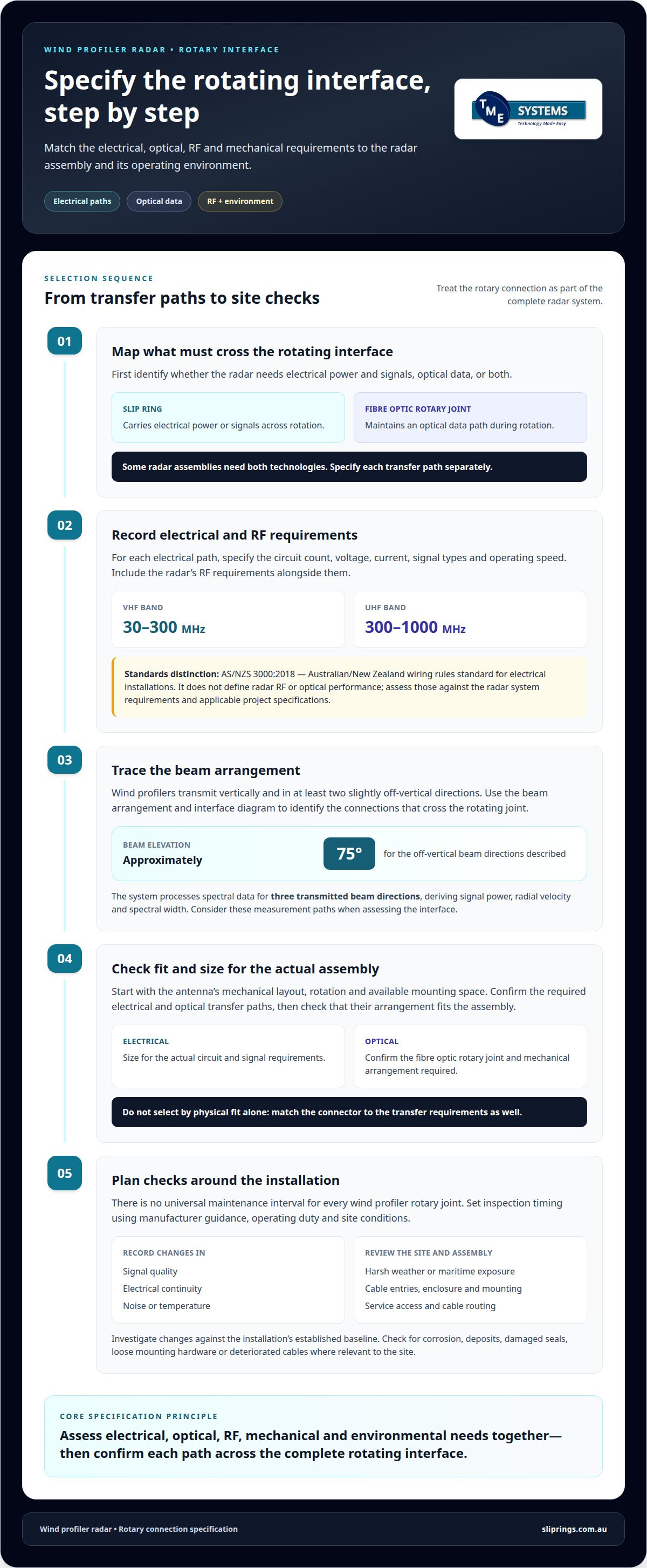
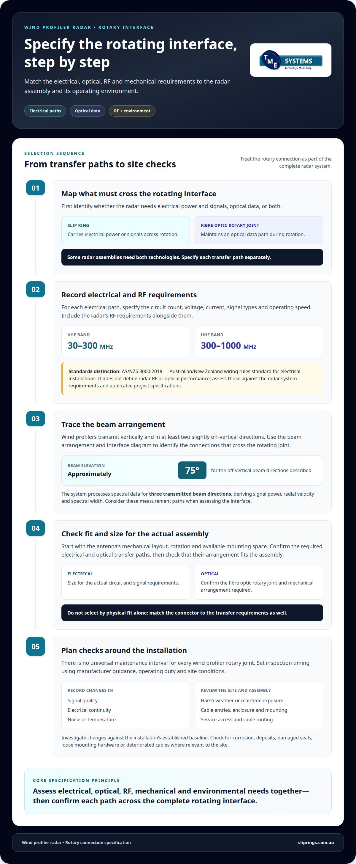
A rotating radar may need to transfer electrical power, signals, optical data or a combination of these. Wind profiler beam processing and operating frequency help determine which paths must cross the rotating interface.
Electrical and RF Specifications
Specify the circuit count, voltage, current, signal types and operating speed for each electrical path. Wind profilers most often operate in the VHF band of 30-300 MHz or the UHF band of 300-1000 MHz. The rotary interface must suit the signals it carries, while an optical path requires a fibre optic rotary joint.
For Australian electrical installations, AS/NZS 3000:2018 is the Australian/New Zealand wiring rules standard. It does not define radar RF or optical performance; assess those against the radar’s system requirements and applicable project specifications.
Connector Selection and Sizing
Start with the antenna assembly’s mechanical layout, rotation, available mounting space and required transfer paths. Then distinguish electrical circuits from optical data channels. A slip ring transfers electrical power or signals across a rotating interface; a fibre optic rotary joint transfers optical data. Some radar assemblies need both.
Wind profilers transmit vertically and in at least two slightly off-vertical directions, at approximately 75 degrees elevation. Use the system’s beam arrangement and interface diagram to identify connections crossing the rotating joint. Size the assembly for its actual circuit and data requirements, rather than selecting by physical fit alone.
Maintenance and Replacement
There is no universal maintenance interval for every wind profiler rotary joint. Set inspection timing according to the component manufacturer’s guidance, operating duty and site conditions. During scheduled system checks, record changes in signal quality, electrical continuity, noise or temperature, then investigate any departure from the established baseline.
Wear, contamination, misalignment or a damaged interface can interrupt power, distort signals or break data transmission. Any of these faults can affect radar availability or the quality of returned measurements. Base replacement decisions on the fault, connector condition and system requirements, rather than an assumed service life.
Wind profiler processing also shapes connection requirements. The system processes spectral data for three transmitted beam directions, deriving signal power, radial velocity and spectral width. A rotary connector that causes interruptions or signal disturbance may compromise these measurement paths, so assess performance across the complete rotating interface.
Optical and electrical transfer serve different purposes. A fibre optic rotary joint maintains the optical data path through rotation, while a slip ring carries electrical circuits. If the radar uses both, specify each path separately and confirm their mechanical arrangement fits the antenna assembly. This distinction supports practical selection without treating every rotary connector as interchangeable.
Operation in harsh weather and maritime conditions
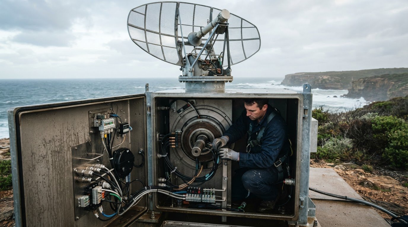
Exposed airfields and military bases can subject radar antennas to harsh weather. Maritime radar rotary joints also face salt water and rough seas. These conditions make the rotating interface part of the environmental design, not just an electrical connection. Specify the installation location and exposure alongside the radar’s electrical and mechanical requirements.
Salt deposits and moisture can affect exposed surfaces, cable entries and mating interfaces. During design, consider how the joint is enclosed, how cables enter the assembly and whether the mounting arrangement leaves vulnerable connections exposed. The protective enclosure must suit the installation while allowing the connector to perform its intended rotational function.
For a coastal or vessel-mounted system, assess the complete assembly rather than the rotary joint alone. Include the support structure, fasteners, cable routing and nearby seals in the review. A suitable connector can still be undermined by exposed connections or mounting details that let salt water reach sensitive areas.
- Site exposure: distinguish an exposed airfield installation from a maritime installation regularly exposed to salt water and rough seas.
- Interfaces: review cable entries, connector orientation and enclosure joints as possible paths for moisture or contamination.
- Mounting: assess whether the installed position shields vulnerable surfaces and supports the rotating assembly.
- Service access: plan access for inspection without disturbing cable routing or protective features.
Weather exposure should also inform maintenance planning. Establish an inspection routine based on the actual site, operating duty and manufacturer guidance. Look for visible corrosion, deposits, damaged seals, loose mounting hardware or deteriorated cables. Record these observations alongside electrical continuity and signal performance checks, so changes can be assessed against the installation’s own baseline.
On a vessel, rough seas add mechanical movement around the radar installation. Review how the connector is supported and how cables are restrained through rotation. Avoid arrangements that place unnecessary strain on cable terminations or allow moving parts to interfere with the joint. At an exposed Australian airfield, consider local exposure and access when planning enclosure placement and inspection.
No single environmental specification suits every radar site. Select the rotary connector according to the system’s exposure, mounting geometry, electrical paths and operating conditions. A site-specific review helps identify weak points across the assembly before installation, rather than treating salt water or weather protection as a connector-only issue.
Rotating radar installations
A rotating radar installation must transfer power and data across a moving interface. Most military radar applications require 360 degrees of coverage. That requirement makes the rotary connection part of the antenna’s operating architecture, rather than a fixed cable connection.
Begin by mapping which components rotate and which remain stationary. For example, an antenna may rotate while its processing equipment stays in a fixed cabinet. The rotary joint sits between these sections, carrying the required electrical circuits or optical data without cables twisting with every turn.
Next, establish the connector’s position within the mechanical assembly. A through-bore arrangement can fit around a shaft, while an end-mounted unit may suit a different layout. Check available space, shaft dimensions, cable entry directions and installation access. The mounting method must keep the joint aligned with the rotating axis.
- Rotation: define whether the antenna turns continuously or changes direction, then match the connector’s operating requirements.
- Connections: map power, control signals and data paths between stationary and rotating equipment.
- Mounting: document the shaft, available envelope and fixing points before choosing a connector format.
- Cable routing: allow for movement at the interface and prevent cables from rubbing against rotating parts.
Mechanical alignment affects the interface throughout operation. An offset mounting position can put unwanted force on the connector and connected cables. Include the joint in the assembly drawing, showing its centreline, support points and cable routes. This helps identify clashes before installing the radar hardware.
Rotation also affects how signals and power pass between the antenna and fixed equipment. Separate circuits requiring electrical transfer from channels using fibre optics. If both types cross the rotating boundary, account for each connection in the layout and confirm the complete assembly can accommodate them.
Finally, assess the installation as a system. The antenna, shaft, rotary joint, mounting hardware and cable routes must work together through the required movement. For a radar needing 360 degrees of coverage, the design should preserve the connection across the full sweep without cable interference or mechanical obstruction.
When comparing options, use the installation requirements already documented as the basis for the specification. BGB says its fibre optic rotary joints and slip ring assemblies are developed for radar installations designed to operate around the clock, 365 days a year. Consider this stated duty context alongside the required rotation, mounting arrangement and cable paths, so the selected interface is assessed as part of the complete assembly rather than as an isolated component. Keep the stated operating duty visible in the design review and check that the chosen configuration addresses the application’s documented needs.
BGB says its fibre optic rotary joints are available in differing physical sizes, data channels, capacities, media converters and wavelength division multiplexers to suit each installation. Use these variations to guide selection: compare physical size with the available space and shaft arrangement, then identify the data channels and capacity required at the rotating boundary. If media conversion or wavelength division multiplexing is part of the installation, include it in the configuration review. Recording these choices alongside mounting and routing details gives the design team a basis for checking fit and signal paths before installation. It also keeps optical data and mechanical integration within one coordinated specification.
What electrical and RF specifications must a wind profiler radar rotary joint meet?
A rotary connector for a wind profiler radar system must suit the radar’s RF path as well as its electrical interfaces. Define the RF connector type, impedance and acceptable signal loss from the system design. These parameters help assess whether the joint can pass transmitted and received signals without undermining intended radar performance.
For RF transfer, specify the operating band and required signal path across the rotating interface. Consider insertion loss, return loss and shielding as part of the RF assessment. Acceptable limits depend on the radar design, so record the system requirements rather than assuming a generic rotary joint will meet them.
- RF interface: document impedance, connector type and the system’s allowable signal loss.
- Electrical paths: identify the power and control connections, including their voltage and current requirements.
- Signal integrity: state the requirements for isolation, continuity and noise across the rotating interface.
- Installation: include rotation, mounting and environmental conditions in the specification.
Size electrical connections for the connected equipment and its operating conditions. Specify the required circuit count and distinguish power connections from sensitive control signals. Check contact resistance and electrical isolation against the radar’s design criteria. These details help avoid a configuration that fits mechanically but does not meet the electrical requirements.
Also document how RF cables connect to the rotary interface. Connector compatibility, cable routing and shielding continuity all affect integration. For example, changing connector orientation can affect the installation drawing and cable path, even when the electrical design remains unchanged.
Separate RF requirements from optical data requirements in the specification. An electrical slip ring does not provide an optical path; a system requiring fibre-optic transfer needs a compatible fibre optic rotary joint. If both media cross the rotating boundary, list their interfaces separately so the assembly can accommodate each.
Finally, consolidate the requirements into one interface schedule. Include RF parameters, electrical circuits, signal integrity criteria, mounting details and exposure conditions. Selecting a rotary connector for a wind profiler radar system then means comparing options against defined system needs, rather than relying on the connector’s label or physical fit alone.
What lead time should you plan for an industrial radar rotary joint in Australia?
Plan procurement around the rotary joint’s configuration and the information needed to specify it. A standard electrical slip ring and an assembly combining electrical circuits with an optical data path have different selection requirements. The design, supply route and project review all affect when the unit can be integrated.
Document the application before setting a delivery milestone. Include the radar model, antenna mounting arrangement, rotation profile, RF requirements, circuit count and environmental exposure. For example, a maritime installation with a defined enclosure and cable route has a clearer specification than a project still resolving its mechanical layout.
Then separate the main schedule stages. Each depends on the decisions and information available at the preceding stage:
- Specification: confirm electrical, optical, mechanical and environmental requirements.
- Configuration: determine whether a standard unit fits or a tailored assembly is needed.
- Engineering review: resolve mounting, interfaces and integration details.
- Supply and installation planning: coordinate delivery with the radar project’s assembly sequence.
A tailored rotary joint can require more design coordination than a standard configuration. Additional channels, a specific shaft arrangement or combined electrical and fibre optic transfer can introduce interface decisions. Final drawings and connection details help resolve those decisions before committing equipment to the radar assembly.
Supply planning also depends on the selected product and its route into Australia. Account for order coordination, transport and receiving checks alongside the project’s installation sequence. A delivery date alone does not cover the time needed to integrate the joint with the antenna and confirm its connections.
Build schedule allowances around known project dependencies, not an assumed universal lead time. Identify when the mechanical drawing, electrical schedule and radar interface details will be available. Set internal milestones for specification approval, procurement, delivery and integration, then track them against the installation plan.
For a wind profiler project, late changes to frequency, signal paths or mounting can affect connector selection and delay integration. Where practical, finalise those requirements before procurement. If the design changes, assess the effect on the joint configuration, drawings and installation sequence together. This gives the project team a clear basis for managing schedule risk without relying on a generic estimate.
TME Systems
TME Systems can help match radar requirements with a suitable slip ring and its interfaces. Technical Application Consulting connects application details with electrical and mechanical requirements, including intended rotation, mounting arrangement and signals passing through the joint. This is useful when the radar design is still being specified or an existing rotating assembly needs a replacement connector.
A technical discussion can begin with the radar’s operating requirements and the role of the rotary interface. Useful details include circuit count, voltage and current requirements, signal types, rotation profile, available mounting space and site conditions. For example, an exposed installation and a sheltered equipment room present different environmental considerations. Clear information helps focus selection on the actual application.
TME Systems supplies slip rings from Mercotac®, Meridian Laboratory - ROTO‑CON, BGB Innovation and Prosper Rotation. Each manufacturer is selected for a different strength, helping match the right slip-ring technology to the application. A rotating profiler may need power and electrical signals to cross the interface, while another design may have different circuit or mounting requirements. The system’s connection diagram and mechanical layout help define the right fit.
- Application: describe the rotating equipment and how the rotary joint fits into the radar assembly.
- Electrical paths: list the required circuits, signal types and electrical loads.
- Mechanical fit: provide the mounting arrangement, shaft details and available space.
- Operating environment: explain whether the equipment faces exposed weather or maritime conditions.
For projects considering Prosper Rotation slip rings, application details can help clarify whether the product family aligns with the intended system. The same method applies when considering Mercotac, Meridian Laboratory or BGB Innovation options. Technical application consulting focuses on the reader’s stated requirements and the suitability of the slip ring within the overall assembly.
Bring together the radar interface information, mechanical drawing and operating conditions for a focused discussion. If the specification is still developing, identify open decisions, such as the mounting arrangement or required circuits. This gives the technical review a clear starting point without assuming a connector configuration before understanding the application.
Contact TME Systems to discuss your radar rotary connector requirements.
Frequently Asked Questions
What type of rotary connector is used in a wind profiler radar system?
The connector type depends on what must pass between the stationary and rotating equipment. Slip rings transfer electrical power or signals; fibre optic rotary joints maintain an optical data connection. A radar using both electrical circuits and fibre-optic data may need both types. Define the signal medium and interface first, then match the connector to the antenna assembly’s electrical and mechanical design.
Which manufacturers supply rotary joints or slip rings for wind profiler radar systems?
TME Systems supplies industrial slip rings from Mercotac®, Meridian Laboratory - ROTO‑CON, BGB Innovation and Prosper Rotation. Each manufacturer is selected for a different strength to match the right slip-ring technology to the application. Meridian Laboratory - ROTO‑CON connectors include through-bore and high-current options, while Prosper Rotation offers fibre-optic rotary-joint options. BGB Innovation supplies industrial slip-ring assemblies, and Mercotac® offers compact, mercury-wetted connectors. Selection depends on application requirements, not the manufacturer name alone.
How do rotary joints compare with slip rings and rotary couplers for radar antennas?
These terms describe different functions, so identify the transfer medium before comparing components. A slip ring carries electrical power or signals across a rotating interface; a fibre optic rotary joint carries optical data. “Rotary coupler” can refer to a rotating interface, but the term alone does not establish whether it transfers RF, electrical or optical signals. For example, specify the required path between the antenna and stationary equipment.
What installation, grounding, and weatherproofing requirements apply to outdoor radar rotary connectors?
Installation details depend on the electrical design, connector specification and site exposure. AS/NZS 3000:2018 is the Australian/New Zealand wiring rules standard for electrical installations. Specify the IP rating for the required dust and water protection, and follow the connector’s mounting and cable-entry requirements. For an exposed radar site, assess enclosure interfaces and cable entries as part of the weatherproofing design, rather than considering the connector alone.