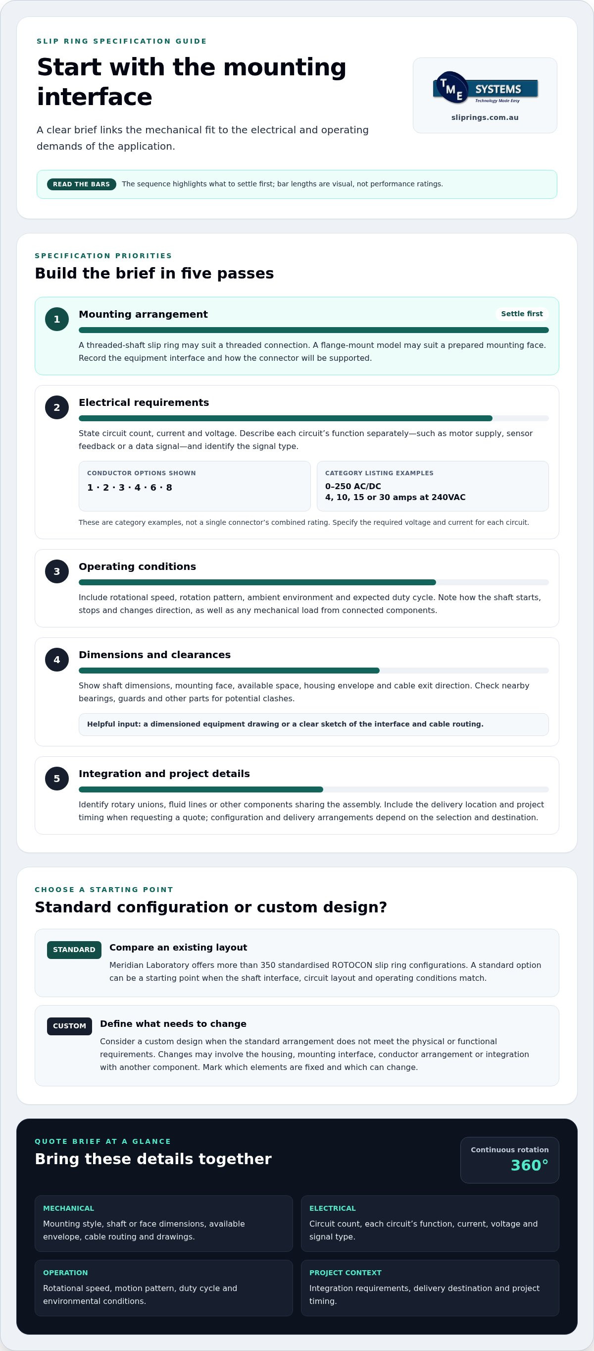
Settle the mounting interface first. A threaded-shaft slip ring may suit equipment designed around a threaded connection, while a flange-mount model may fit a prepared mounting face. To get a quote for a rotary connector, include the mounting arrangement and key electrical and operating requirements, such as circuit count, current, voltage, speed and environmental conditions.
It’s understandable to want a configuration that fits the equipment without overlooking the demands of power or signal transmission. This article explains how threaded-shaft and flange-mount options differ, which application details guide selection, and what to include in a quote request. You’ll also see how mounting style relates to the wider choice of rotary electrical connector, so you can prepare a clear technical brief for your application.
Key Takeaways
- Match the mounting style to the equipment interface: threaded-shaft and flange-mount configurations suit different mechanical arrangements.
- Set out the power and signal requirements clearly, including circuit count, current and voltage.
- Include rotational speed and operating environment in your specification, as these affect slip ring selection.
- Compare standard configurations with customisation needs to identify a suitable rotary electrical connector.
- Provide drawings or key dimensions with your enquiry to help clarify the fit and connection requirements.
Electrical slip rings for 360° power and signal transmission
A slip ring maintains electrical continuity between stationary equipment and a rotating assembly. It transfers power, control signals or both across a continuous 360° rotation, avoiding cables that twist with the shaft. Specify each circuit’s function separately: a motor supply, sensor feedback and a data signal can impose different requirements on one rotary electrical connector.
A mercury-wetted rotary electrical connector maintains contact through conductive mercury between stationary and rotating contacts. This allows continuous rotation without a conventional sliding-brush arrangement. If your design calls for this technology, specify the exact connector type and operating conditions rather than assuming all liquid-metal connectors use the same conductive material.
Brushless rotary connectors can use conductive liquid metal to maintain electrical continuity, avoiding brush wear and reducing noise. Mercury-free liquid-metal designs use gallium-based alloys instead of mercury. When comparing contact methods, consider the signal requirements and the equipment’s environmental conditions.
How do slip rings compare with other rotary electrical connectors? Slip rings pass electrical power or signals across rotating contacts; a rotary union transfers fluid between stationary and rotating equipment. Some applications need both functions, but each connector must be specified for its own electrical or fluid requirements. Category options include 1, 2, 3, 4, 6 or 8 conductors.
Electrical ratings need to match the load, not just the connector’s physical fit. Category listings include 0-250 AC/DC and current ratings of 4, 10, 15 or 30 amps at 240VAC. These are category examples, not a single connector’s combined rating. State the required voltage and current for each circuit, alongside signal type and rotational speed.
A rotary union carries fluid through dedicated passages, while a slip ring transfers electrical circuits. A through-bore slip ring can leave a central route for a shaft or auxiliary components such as hydraulic lines. Provide a layout showing the shaft, fluid path and electrical connections so clearances and mounting can be assessed together.
What certifications and Australian electrical standards apply to rotary connectors? AS/NZS 3000:2018 is the Australian/New Zealand wiring rules standard for electrical installations. It concerns the installation, not a blanket product certification; specify the connector’s application and installation context when assessing applicable requirements.
For installation and maintenance planning, document the expected maintenance approach, installation responsibilities and relevant warranty terms. Include the mounting arrangement and access requirements so the plan reflects the actual equipment layout.
Lead times and delivery arrangements depend on the selected configuration, whether it is standard or customised, and the Australian delivery destination. Include the required delivery location and project timing in your enquiry so the proposed configuration and delivery plan can be considered together.
Standard configurations and customisation
A standard slip ring configuration can shorten specification work when its mechanical layout and electrical functions match the application. Meridian Laboratory offers more than 350 standardised ROTOCON slip ring configurations. That range gives engineers a starting point for comparing assemblies before defining any changes. A standard option may suit a machine with a familiar shaft interface, established circuit layout and known operating conditions.
Start by mapping the equipment interface. Record the available space, shaft or mounting arrangement, housing envelope and cable exit direction, then compare them with a standard assembly drawing. A connector may fit the available diameter but still clash with a bearing or guard if housing length is overlooked. A dimensioned drawing can reveal these conflicts before the design is finalised.
Custom design is relevant when a standard arrangement does not meet the equipment’s physical or functional requirements. Changes may involve the housing shape, mounting interface, conductor arrangement or integration with another component. Consider each change in the context of the whole assembly: a longer housing can affect clearances, while a revised shaft interface can change how the assembly is supported.
A custom slip ring project starts with a defined application brief. Include a drawing or sketch and identify which elements are fixed and which can change. Useful design inputs include:
- Mechanical interface: shaft dimensions, mounting face, available envelope and cable routing.
- Operating conditions: rotation pattern, ambient environment and expected duty cycle.
- Integration needs: nearby bearings, rotary unions, fluid lines or other parts sharing the assembly.
- Performance priorities: whether the design favours compact packaging, low torque or straightforward installation.
Consider torque because connector resistance can affect the drive system. Describe how the shaft starts, stops and changes direction, and note whether connected components add mechanical load. An intermittently indexed turntable, for example, has a different motion profile from a continuously rotating inspection platform. These details help assess the application as a system.
Custom design and manufacturing translate approved requirements into a buildable assembly. Check the proposed interface and overall dimensions against the machine drawing, and resolve clashes during design review. Keep revision numbers consistent across the connector specification and equipment drawings to avoid incorrect assumptions about fit.
For a standard starting point, review Meridian Laboratory slip ring configurations alongside your application drawing. A clear comparison between the ROTOCON configuration and the required housing, mounting and integration details helps identify where standard selection ends and custom engineering begins.
Meridian Laboratory's MXV Series is designed for high-voltage applications >600. Meridian Laboratory's MM Series slip rings are specified for speeds of 2K - 10K RPM, providing further options to assess against application requirements.
Quote request call to action
A useful rotary connector quote relates the proposed configuration to the machine’s operating requirements. Provide enough context to assess whether the connector’s electrical functions, mounting arrangement and operating conditions suit the equipment. A request based only on a product category leaves key selection criteria unclear.
Prepare a concise application summary before requesting a quote. Identify the machine, describe what the connector must transfer and explain how the rotating assembly operates. For example, a packaging machine may need sensor signals through a rotating turntable, while a crane may require a high-current connection. This context is more useful than a product category alone.
State the operating conditions: circuit functions, current, voltage, rotational speed, rotation pattern and ambient temperature. Note whether the machine runs continuously, indexes between positions or reverses direction. A connector in a warm enclosure may need different consideration from one in a cool, clean environment.
Mechanical information is just as important. Provide a dimensioned drawing or clear sketch showing the shaft, mounting face, available space and cable route. Mark fixed dimensions and areas that can change. If the connector sits near a rotary union, bearing or hydraulic line, include those parts in the same layout to make clashes and interface constraints easier to assess.
Make your request easier to review by organising the information in a short checklist:
- Machine and task: identify the equipment and explain the connector’s function.
- Electrical requirements: list each circuit’s purpose and required operating values.
- Motion and environment: describe speed, duty pattern, temperature and exposure conditions.
- Mechanical interface: attach drawings with dimensions, mounting details and nearby components.
- Project scope: state whether you need a standard configuration or a custom arrangement.
Separate essential requirements from preferences. For example, mark the shaft diameter as fixed but describe the cable exit direction as adjustable if the machine layout allows. This keeps a preferred feature from obscuring a critical fit requirement. Include the drawing revision and machine model where available, so the connector specification refers to the correct design.
Before sending the request, check that the electrical schedule and mechanical drawing describe the same assembly. Resolve any mismatch, such as a different cable route or mounting face. A complete, consistent brief gives the technical review a practical basis for comparing configurations and clarifying the proposed interface, operating assumptions and design decisions.
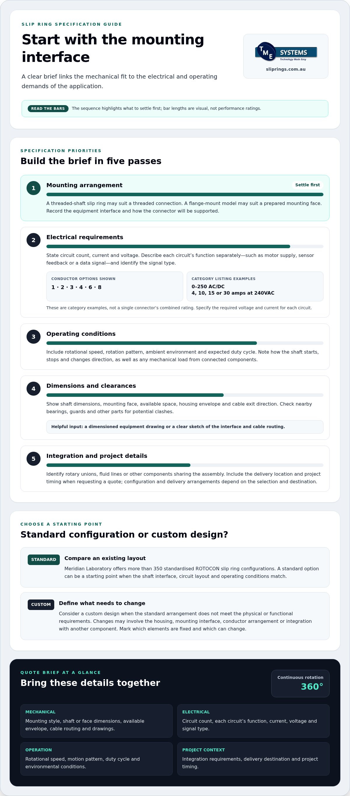
Information needed to specify a slip ring
A useful specification links the electrical schedule to the machine’s design and operating task. It also distinguishes essential requirements from areas where there is flexibility.
Slip ring specification details
Describe each circuit by its function, not simply as a spare channel. Distinguish, for example, a sensor feedback path from a control command or data link. Note whether circuits share a common reference or require electrical isolation. This schedule clarifies how the slip ring connects to the machine’s control system and avoids grouping different functions under an ambiguous label.
Explain how the equipment is controlled during operation. A machine that pauses at set positions may have different signal-transfer requirements from one that rotates continuously. Identify changes in operating mode, such as switching between manual setup and automatic production, so the connector can be assessed against the machine’s actual control sequence.
Factors affecting rotary connector selection
Compare proposed connectors against the required signal types, circuit arrangement and operating pattern. Check that the specification covers the complete system, including its interface with control equipment. If the design carries both power and sensitive signals, explain which circuits operate together so their interaction can be considered.
Use signal terminology precisely. Ethernet, fieldbus, analogue signals and fibre-optic signals are distinct transmission types, not interchangeable descriptions of “data”. State the protocol or signal format where known. Naming an Ethernet connection, for example, is more useful than describing it only as a high-speed signal.
Use a circuit schedule to make requirements easy to review. Include a circuit identifier, its function, the connected equipment and relevant interface notes, and keep the schedule consistent with the machine’s electrical documentation. If replacing an existing connector, record its current circuit assignments and explain planned changes instead of assuming the old arrangement remains suitable.
Consider how the connector fits into the control system. Identify the equipment on each side of the rotating interface and describe the expected behaviour if a signal is interrupted. This helps distinguish essential control paths from monitoring or optional data paths and clarifies the consequences of a circuit change.
Before finalising the specification, compare it with the machine’s electrical and mechanical design records. Resolve inconsistent circuit names or interface descriptions and record the assumptions used for selection. A clear, shared specification helps assess whether a proposed slip ring suits the intended control function and equipment architecture.
Threaded-shaft and flange-mount configurations
Mounting style determines how the rotary connector interfaces with the machine. Threaded-shaft and flange-mount arrangements require different dimensions, clearances and retention details in the specification.
A threaded shaft connects through a threaded interface, so identify the thread details and available shaft length from the equipment drawing. Show the shoulder, adjoining components and required clearances too. A mismatch between the connector interface and the machine thread can prevent correct installation, even when the electrical requirements align.
Threaded shafts also appear on rotary unions, which transfer fluid rather than electrical circuits. For example, the Series RU012 rotary union has 2 passages and a threaded shaft. The Series RU014 has 3 passages and a threaded shaft, while the Series RU018 has 5 passages and a threaded shaft. These examples describe rotary unions, not electrical slip rings.
A flange-mount configuration attaches to a mounting face on the equipment. Provide the flange outline, fixing-hole positions, available depth and cable exit direction. Show how the flange sits relative to the rotating shaft and nearby structure. A guard or bearing housing, for example, may limit fastener access or the space behind the mounting face.
Compare the arrangements against the machine’s physical constraints rather than choosing by name alone. A threaded connection may suit an interface designed around a shaft thread; a flange may suit equipment with a prepared mounting face. In either case, the assembly must be supported and positioned as intended. Include nearby unions or fluid lines if they affect clearance.
Include these details with the application drawing for either mounting style:
- Interface: thread description or flange dimensions and hole positions.
- Envelope: available length, diameter, depth and access for installation.
- Orientation: shaft direction, fixed and rotating parts, and cable exit route.
- Integration: nearby bearings, guards, unions and other machine components.
Make sure the drawing clearly identifies the fixed structure and rotating shaft. Add the drawing revision and mark dimensions that cannot change. If the mounting face or shaft is still being designed, state which dimensions remain adjustable. This separates firm interface requirements from preferences and gives the technical review a clear basis.
When you want to get a quote for a rotary connector, submit mounting details alongside the electrical requirements. A threaded-shaft slip ring and a flange-mounted slip ring cannot be compared accurately using circuit needs alone. The mounting drawing, operating arrangement and required electrical functions together define the configuration to assess.
Whether the shaft or housing rotates depends on how the rotary union is mounted and installed. Industry best practice advises against rigidly bolting both the shaft and housing in place, recommending that one component be allowed some movement in case of misalignment. A through-bore rotary union leaves space at the centre for electrical wires or other components and can also mount the union to a custom interface. Account for this opening when checking the layout and installation approach.
TME Systems: Mercotac Slip Rings
TME Systems Pty Ltd provides technical application consulting to help translate your requirements into a suitable slip ring specification. Use this support when circuit count, current, voltage, speed, mounting style or environmental conditions need to be considered together.
For a Mercotac option, review the Mercotac Slip Rings range alongside your machine requirements. TME Systems Pty Ltd also supplies Meridian Laboratory, BGB Innovation and Prosper Rotation Slip Rings, giving you further product ranges to consider against the application.
Bring your drawings and operating details when discussing a configuration. They give the technical review a practical basis for matching the connector to your equipment and identifying key selection criteria.
Contact TME Systems Pty Ltd to discuss your slip ring application.
Move your rotary connector specification forward
Before finalising a design, align the connector specification with the machine drawing and project operating requirements. This gives the technical review a defined basis for assessing fit and function, especially when the mounting interface or equipment layout is still changing.
To get a quote for a rotary connector, prepare the relevant drawings and application details, then contact TME Systems. Its range includes Mercotac Slip Rings, Meridian Laboratory Slip Rings and BGB Innovation Slip Rings. Technical application consulting can help match these options to your equipment requirements.
A clear next step is to share the proposed mounting arrangement and the electrical functions the connector must support. This keeps the conversation focused on your application and helps identify the information needed to progress the specification. Contact TME Systems for a quote and take the next step towards a suitable rotary connector for your project.
Frequently Asked Questions
What is a rotary connector and what types are available?
A rotary connector transfers power, signals or data between stationary and rotating parts of equipment. Slip rings are one common type, with options including conventional assemblies, brushless mercury-wetted connectors, through-bore designs and fibre-optic rotary joints. The right type depends on what must pass through the rotating interface. An automated turntable, for example, may need electrical power and control signals, while another application may require fibre-optic data transfer.
What details are needed to request a quote for a rotary connector?
To get a quote for a rotary connector, describe the machine’s function and provide the information needed to assess signal compatibility. Identify whether the application uses analogue signals, Ethernet, fieldbus or fibre-optic signals, and explain which functions operate together. Include relevant electrical and mechanical drawings with their revision details. This links the requested signal paths to the machine layout rather than treating each requirement in isolation.
What technical specifications should I compare when choosing a rotary connector?
Compare the connector’s electrical ratings with the machine’s operating profile, including current, voltage, signal or data type and speed. Assess the mounting interface, available space and environmental exposure as well. An IP rating describes protection against dust and water ingress, so compare it with the equipment’s location and conditions. Include changing temperatures or harsh surroundings in the technical assessment alongside the electrical requirements.
What warranty, maintenance, and installation costs should I check before ordering?
Before ordering, document the warranty terms, expected maintenance approach, installation responsibilities, mounting arrangement and access requirements.