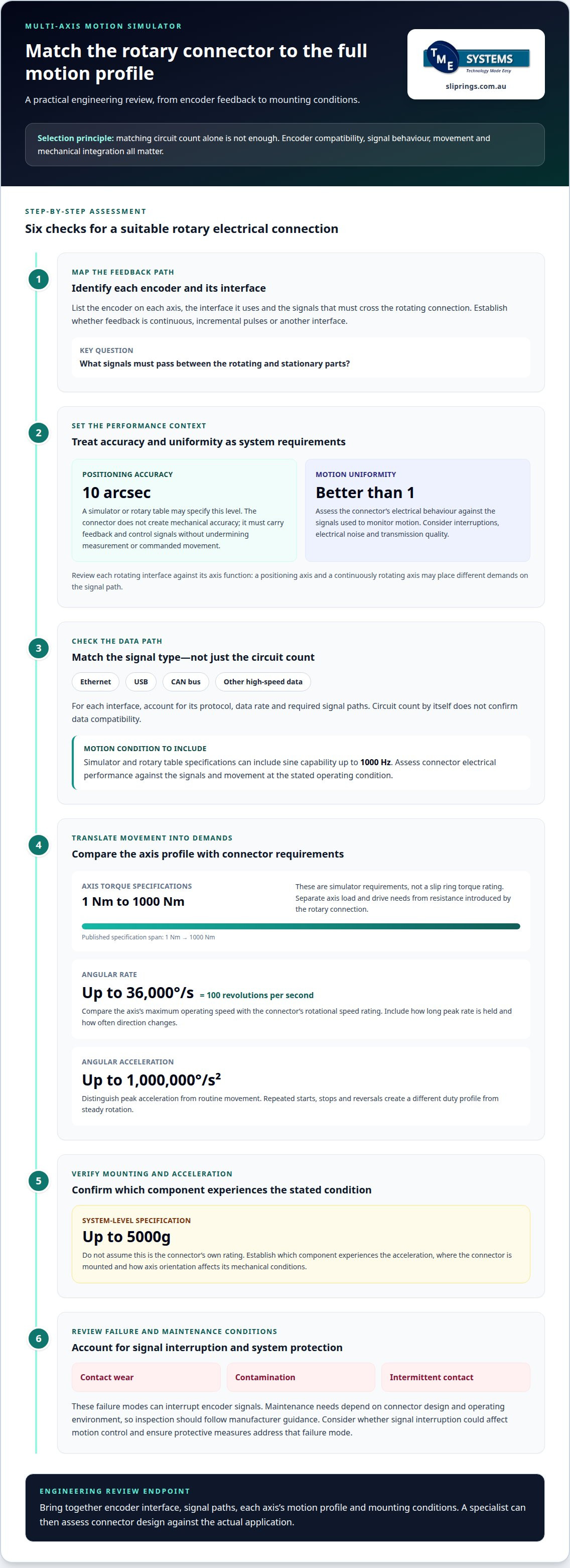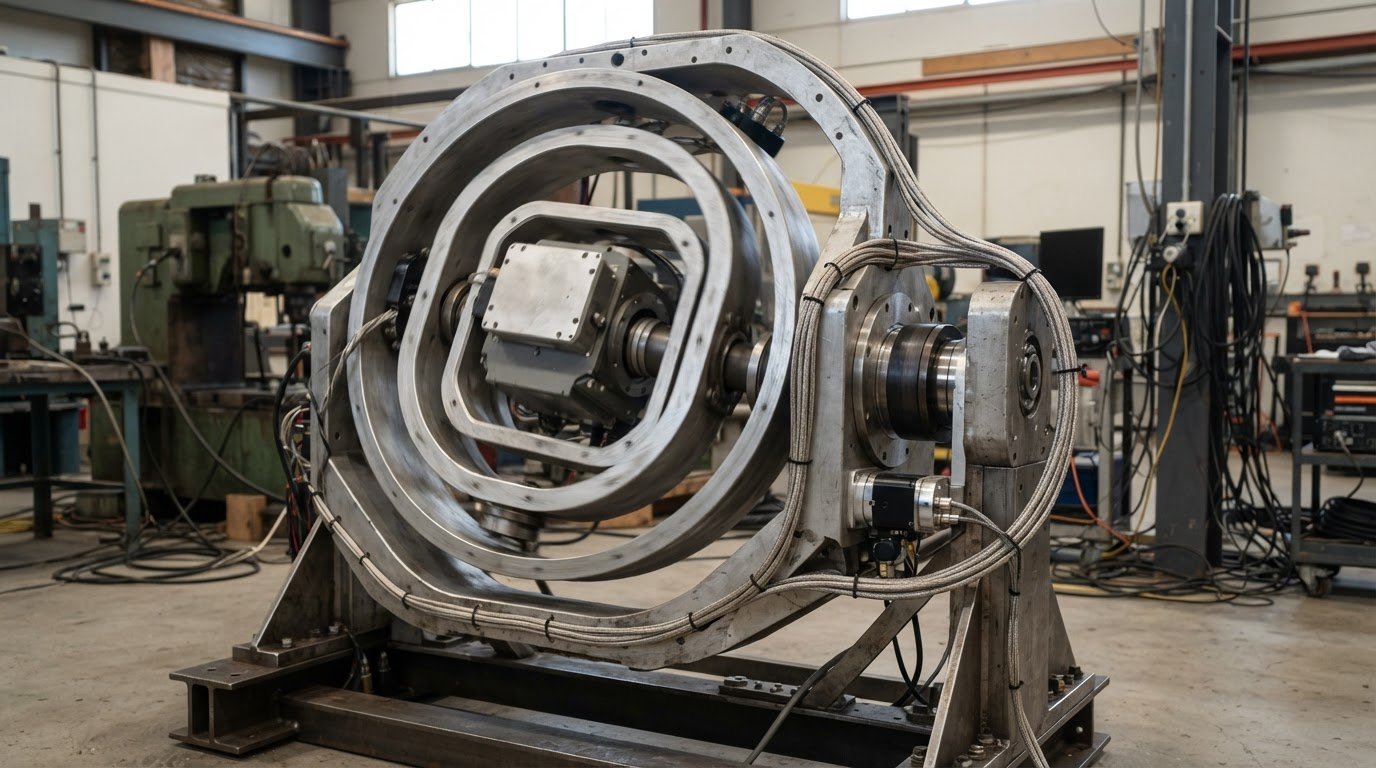
The connector that suits an axis electrically may still be a poor fit for its motion profile. A rotary connector for a multi-axis motion simulator must match the encoder interface and positioning requirements while maintaining consistent signal transfer as torque, angular rate and angular acceleration change. Simulator specifications can include positioning accuracy of 10 arcsec and motion uniformity better than 1, so connector selection needs to account for the complete operating profile.
Choosing a rotary connector for a multi-axis motion simulator involves more than matching the circuit count. Encoder compatibility, mounting arrangement and the demands of each moving axis all affect performance. A mismatch can compromise the signals needed for accurate control and measurement.
This article explains how to assess encoder compatibility, positioning accuracy and motion uniformity, then relate torque, angular rate and angular acceleration to connector requirements. It also outlines the application details a technical specialist uses to narrow the options, including where slip ring design and mounting configuration influence selection.
Key Takeaways
- Match encoder compatibility and signal requirements to the simulator’s control and measurement systems.
- Assess positioning accuracy and motion uniformity alongside the full movement profile of each axis.
- Use torque, angular rate and angular acceleration requirements to narrow suitable connector designs.
- Distinguish slip rings from rotary joints and cable management systems by how each handles rotation and signal transfer.
- Allow an application engineer to determine circuit count, current, voltage and data channels from the system requirements.
Positioning accuracy and motion uniformity
Positioning accuracy describes how closely a simulator axis reaches its commanded position. A motion simulator or rotary table may have positioning accuracy of 10 arcsec. The rotary connector doesn’t create that mechanical accuracy. It must carry encoder feedback and control signals without undermining the system’s ability to measure and command movement. Selection therefore starts with the encoder interface, signal type and operating conditions, not the accuracy figure alone.
Motion uniformity describes how consistently an axis moves through its travel. Motion simulators and rotary tables are specified with motion uniformity better than 1. Treat this as a system-level performance requirement: the connector’s electrical behaviour must suit the signals used to monitor motion. The engineering review should identify whether the encoder reports position continuously, provides incremental pulses or uses another interface. That distinction affects the signal paths the rotary electrical connection must support.
For a multi-axis system, assess each rotating interface against its axis function. A positioning axis that holds a commanded angle may rely on encoder feedback both while moving and while stationary. A continuously rotating axis may place different demands on the signal path. In either case, intermittent transmission can disrupt feedback or control. Consider the connector’s circuit arrangement, signal compatibility and mechanical integration alongside the simulator’s positioning target.
For Ethernet, USB, CAN bus or other high-speed data, the protocol, data rate and required signal paths all matter when selecting a slip ring. The connector must suit the specific interface; circuit count alone does not establish data compatibility.
Review the motion profile as well as the position target. Motion simulators and rotary tables have sine capability up to 1000 Hz, so the application review should consider the signals and movement involved at that operating condition. The connector’s suitability depends on its electrical performance under the actual motion profile, not simply whether it can rotate. Encoder resolution and feedback requirements also inform how the signal path should be assessed. When designing automated machine simulation and custom robotic equipment, automation specialists like RWC Inc. evaluate these dynamic profiles in advance to ensure electrical and mechanical systems integrate seamlessly.
- Map the feedback path: identify each encoder, its interface and the signals that cross the rotating joint.
- Relate requirements to each axis: distinguish a positioning axis from one that rotates continuously.
- Assess signal behaviour: consider interruptions, electrical noise and transmission quality against the encoder’s role.
Common failure modes include contact wear, contamination and intermittent electrical contact, which can interrupt encoder signals. Maintenance needs depend on connector design and operating environment, so follow the manufacturer’s guidance for inspection. For safety, assess whether signal interruption could affect motion control and ensure the system’s protective measures account for that failure mode.
Torque, angular rate and angular acceleration specifications
Motion simulators and rotary tables can have angular torque specifications from 1 Nm to 1000 Nm. These figures describe a broad range of simulator requirements, not a slip ring’s torque rating. A specialist separates the load and drive requirements of each axis from the connector’s mechanical resistance. The connector must rotate with the assembly without adding unsuitable drag or interfering with controlled movement.
Angular rate describes how quickly an axis turns. Motion simulators and rotary tables can have angular rates up to 36,000 degrees per second, equivalent to 100 revolutions per second. This peak rate makes rotational speed rating a key selection parameter. The slip ring’s permitted operating speed must suit the axis’s actual profile, including how long it runs at peak rate and how often it changes direction.
Angular acceleration describes how quickly the angular rate changes. Motion simulators and rotary tables can have angular acceleration up to 1,000,000 degrees per second squared. This peak matters because frequent starts, stops and reversals create a different duty profile from steady rotation. The selection review should distinguish peak acceleration from the motion used for routine operation.
Specifications also describe accelerations up to 5000g. This figure should be treated as a system-level condition, not assumed to be the connector’s own rating. The application engineer needs to establish which component experiences the stated acceleration and how the connector is mounted. Axis orientation and mounting arrangement affect the mechanical conditions the joint experiences.
- Torque: distinguish the simulator’s axis torque from resistance introduced by the rotary connection.
- Angular rate: compare maximum operating speed with the connector’s rotational speed rating.
- Angular acceleration: account for reversals and rapid changes, not only steady motion.
- Acceleration: identify the component and mounting location associated with the stated 5000g condition.
For example, an axis that briefly reaches 36,000 degrees per second and then stops repeatedly has a different operating profile from one that turns steadily at a lower rate. Both its peak speed and acceleration pattern inform connector selection. A design based only on the highest rate could overlook starts, reversals or time spent rotating.
For each simulator axis, provide torque, peak and routine angular rates, acceleration profile, operating sequence and mounting arrangement. These details help assess whether a connector’s mechanical limits suit the application, while its electrical paths are matched separately to the signals and power being transferred. Selection should reflect the complete motion profile, not one isolated maximum specification.
What type of rotary electrical connector can a specialist recommend for a multi-axis motion simulator?
A suitable rotary electrical connector depends on what each simulator axis must transfer while rotating. Start by separating power, encoder feedback and communication signals, then match their electrical requirements to the mechanical arrangement. For example, an axis carrying encoder feedback and Ethernet has different signal needs from one carrying power alone. No single connector type suits every multi-axis system.
Begin by reviewing the equipment on both sides of each rotating interface. Identify the encoder type, signal protocol, current, voltage and circuit count, then consider how the simulator moves. Intermittent positioning, continuous rotation and repeated reversals place different demands on the assembly. Account for the required data integrity too: a connector that transfers power may not suit sensitive feedback or communication signals. Selecting a rotary connector for a multi-axis motion simulator means assessing these requirements together.
Form factor is another consideration. A through-bore slip ring is a rotary electrical connector with a hollow centre that allows it to be mounted directly over a rotating shaft or to accommodate auxiliary components like hydraulic lines. A capsule slip ring is a compact, solid unit for end-of-shaft mounting. Available space, shaft arrangement and cable routing help determine the appropriate configuration. These mounting considerations narrow the options for a rotary connector for a multi-axis motion simulator.
Assess contact technology against the application rather than choosing by name alone. Liquid metal rotary connectors are brushless rotary connectors that use a pool of conductive liquid metal to maintain electrical continuity, eliminating wear and reducing noise. Consider whether this contact method suits the simulator’s signal types and operating conditions, alongside other connector designs.
Where required circuits combine different functions, a modular system may be worth considering. This architecture allows multiple functional modules to be stacked or combined in one assembly. Assess whether separate power and signal sections suit the axis, rather than treating every connection as interchangeable. The circuit count must reflect the independent electrical paths needed for transmission.
- Encoder feedback: identify the interface and signal characteristics that must pass through the rotating joint.
- Communications: specify protocols such as Ethernet, USB or CAN bus and their data requirements.
- Power: define the voltage and current requirements separately from signal circuits.
- Installation: match the connector’s form and mounting arrangement to the shaft and surrounding components.
For example, a compact end-of-shaft installation may favour a capsule form, while a shaft passing through the connector points towards a through-bore design. Neither example establishes electrical suitability on its own. The final recommendation must reconcile packaging with signal performance, power transfer and each axis’s motion profile. This provides a practical basis for selecting a rotary connector for a multi-axis motion simulator, with its configuration tied to the system’s actual requirements.
How do slip rings differ from rotary joints and cable management systems for motion simulators?
A slip ring transfers electrical power or signals between stationary and rotating parts while allowing continuous rotation. In a motion simulator, it can keep encoder feedback, control signals or power connected as an axis turns. Its purpose is to maintain electrical continuity across a rotating interface. The required circuit arrangement depends on what the simulator must transmit.
A rotary joint commonly refers to a mechanical connection that transfers fluid or gas between stationary and rotating equipment. For example, a simulator using a hydraulic actuator may need fluid routed across a rotating axis. This function differs from that of an electrical slip ring. Some applications need both: a fluid rotary joint for the hydraulic circuit and a slip ring for electrical signals or power.
The term “rotary joint” can also be used broadly for rotary electrical connections. To avoid ambiguity in a specification, define the medium being transferred. State whether the requirement is electrical, fluid, pneumatic or a combination. A hydraulic line passing through a rotating assembly, for instance, needs a fluid-transfer solution; encoder signals need an electrical path.
Cable management systems take a different approach. They guide and protect flexible cables as simulator axes move, rather than transferring electricity through rotating contacts. A cable loop may suit an axis with limited travel that reverses direction before twisting becomes excessive. For continuous rotation, cable winding and torsion can constrain movement, so consider the system’s permitted travel and cable routing.
These options solve different problems, and selection follows the axis movement and connected services:
- Slip ring: maintains electrical paths across a rotating interface, including during continuous rotation.
- Fluid rotary joint: carries a medium such as hydraulic fluid across a rotating connection.
- Cable management: routes flexible cables where movement and cable twist remain within the design limits.
Consider a simulator gimbal with electrical feedback and a hydraulic line. The electrical and fluid paths have separate functions, so one component should not be assumed to replace the other. A combined assembly may suit a design that must accommodate both, but each transfer requirement still needs to be assessed.
For a limited-angle axis, cable routing may avoid a rotating electrical contact if the movement range and cable life suit the duty. For continuous rotation, a slip ring provides an electrical connection without relying on a cable loop to unwind. Compare axis travel, signal and power requirements, fluid connections, mounting space and cable routing before choosing an arrangement. This distinction helps establish whether the simulator needs electrical transfer, fluid transfer, managed cable movement or a combination.
How can an application engineer determine the circuit count, current, voltage, and data channels a motion simulator slip ring needs?
Start with an electrical schedule for each rotating axis. Separate power, encoder feedback, control signals and communications so that a data channel is not treated as interchangeable with a power circuit. Then map which connections cross the rotating interface and which remain on the stationary structure.
Circuit count is the number of independent electrical paths a slip ring provides for power and signal transmission. Count each required path from the system wiring, including separate encoder channels and control circuits. For example, an axis carrying motor power, encoder feedback and a communications link needs each function identified individually. The circuit total follows the actual system architecture, not a general rule for simulator axes.
Assess current and voltage for each power circuit. Review the equipment’s electrical requirements and distinguish continuous operating demand from peaks during operation. Also consider whether multiple circuits carry current simultaneously. These details inform conductor selection and thermal management - techniques used to control temperature rise in a slip ring during operation. Ambient conditions and connector rotational speed can also affect allowable operating limits.
Data channels need a separate compatibility review. Record the interface and protocol for each channel, such as Ethernet, USB, CAN bus or encoder feedback. Data rate, signal type and transmission requirements help determine whether the proposed slip ring can carry those signals reliably. A spare circuit alone does not establish suitability for high-speed data transmission.
- Map connections: identify every electrical path crossing each rotating axis.
- Classify circuits: separate power, feedback, control and communications requirements.
- Record electrical demands: document current and voltage for each power path, including operating peaks.
- Assess data: specify each protocol and signal requirement separately from circuit count.
For a multi-axis simulator, complete this assessment axis by axis. One axis might carry motor power and encoder signals, while another carries additional data channels. Treating them separately avoids applying an unsuitable circuit count or electrical rating across the whole simulator. Relate each axis schedule to its mounting arrangement and motion profile, so mechanical integration and electrical requirements are considered together.
The result is a defined specification for circuit count, current, voltage and data channels, rather than an estimate based on the simulator’s overall size. For a project-specific assessment, request technical application consulting with the axis wiring schedule and interface requirements.
TME Systems
TME Systems Pty Ltd helps match a motion simulator’s electrical and mechanical requirements with a suitable slip ring. This is useful when encoder interfaces, data channels, operating conditions or mounting constraints need to be considered together. Its range includes Mercotac Slip Rings, Meridian Laboratory Slip Rings, BGB Innovation Slip Rings and Prosper Rotation Slip Rings.
For a project assessment, provide the axis wiring schedule, encoder and communications interfaces, current and voltage requirements, motion profile and available mounting space. These details help shape a practical selection around the simulator’s actual requirements rather than a single specification in isolation.
Contact TME Systems Pty Ltd to discuss slip ring selection for your motion simulator.
Turn the specification into a selection brief
Turn the simulator’s requirements into a clear engineering brief. Assess a rotary connector for a multi-axis motion simulator against the system’s actual interfaces and operating conditions, not a single specification. A concise brief can help keep design, controls and procurement teams aligned as the project develops.
Include the axis wiring schedule, encoder and data interfaces, electrical requirements, motion profile and mounting constraints. This gives technical application consulting a practical basis for assessing suitable options. TME Systems supplies Mercotac Slip Rings, Meridian Laboratory Slip Rings and BGB Innovation Slip Rings as part of its range of slip-ring solutions.
If the simulator design is still evolving, note which requirements are fixed and which may change. This helps focus the selection discussion on the interfaces most likely to affect integration. A well-defined brief makes the engineering discussion more specific and keeps connector selection aligned with the machine’s intended operation.
Contact TME Systems about rotary connectors to discuss your application and take the next step towards a suitable selection.
Frequently Asked Questions
Which slip rings support Ethernet, USB, CAN bus, or high-speed data for motion simulators?
A slip ring for Ethernet, USB, CAN bus or other high-speed data should be selected after assessing the protocol, data rate and required signal paths.
What are the torque, rotational speed, angle-of-rotation, and service-life requirements?
Simulator axis torque specifications range from 1 Nm to 1000 Nm, and angular rates reach up to 36,000 degrees per second. A platform can be turned to any position and fixed there. The material gives no service-life requirement; maintenance depends on connector design and operating environment, with inspection following the manufacturer’s guidance.