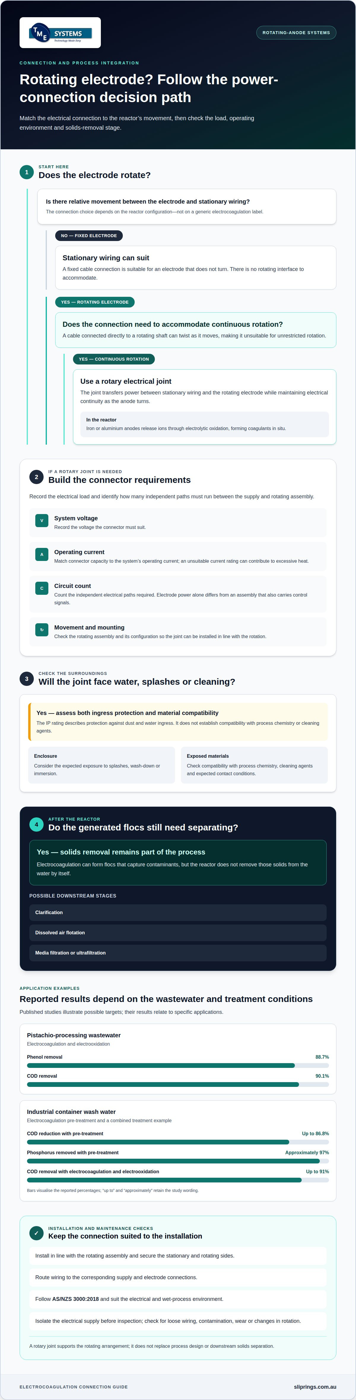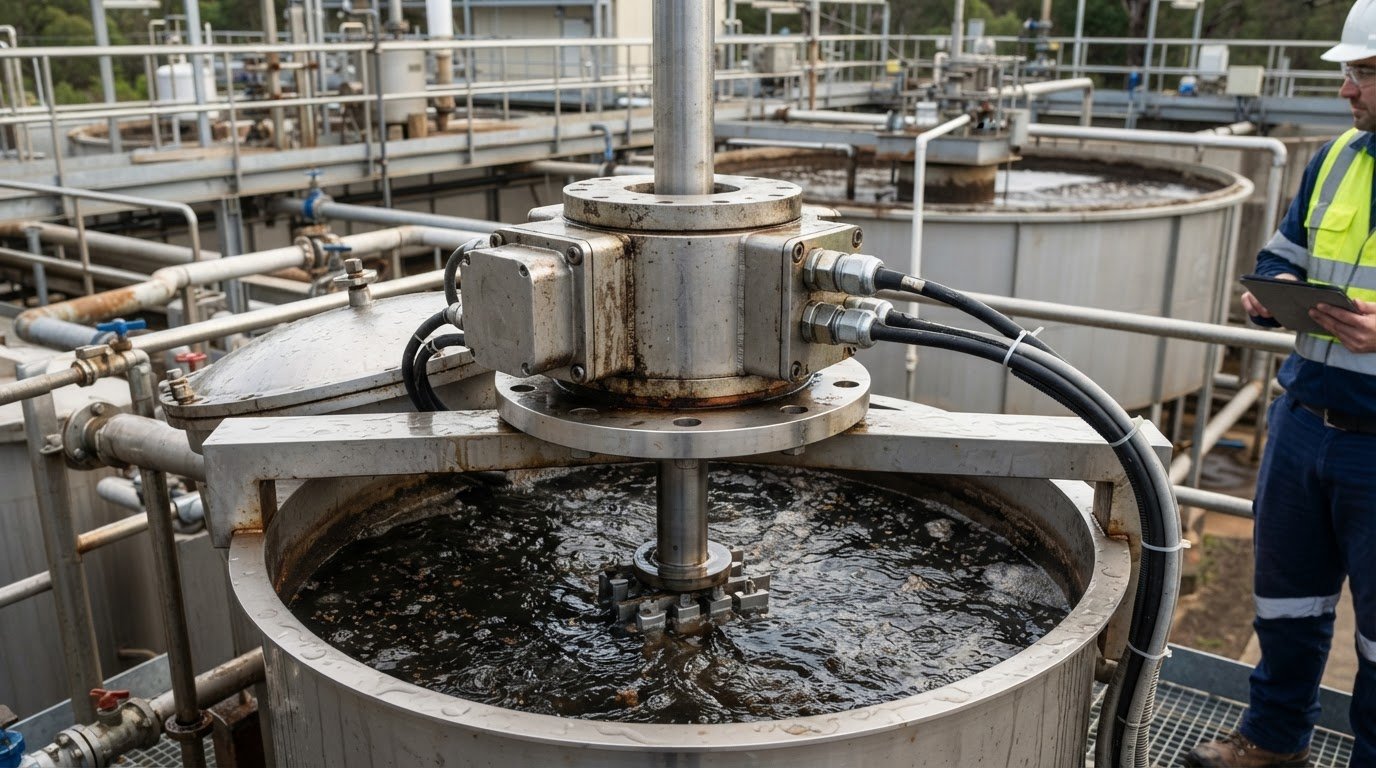
A rotating electrode can support electrocoagulation, but it also creates an electrical connection problem: power must cross from stationary equipment to a rotating component. A rotary connector for electrocoagulation water treatment provides that connection, allowing the system’s electrical and mechanical arrangements to work together.
Electrocoagulation generates coagulants in situ through the electrolytic oxidation of metal anodes. The process can form flocs that capture contaminants, but treatment does not end at the reactor: a solids-removal stage, such as clarification, dissolved air flotation or filtration, is needed to separate them from the water.
The right rotary electrical joint depends on the rotating assembly and its operating conditions, including circuit count, current, voltage, speed, mounting style and environment. This article explains how a rotary connector for electrocoagulation water treatment fits a rotating-anode system, how the process can integrate with existing treatment, and which industrial wastewater applications may benefit. It also covers the connector considerations engineers can use to assess system compatibility, without treating the rotary joint as a substitute for process design or downstream solids separation.
Key Takeaways
- See where electrocoagulation can sit alongside existing treatment stages, and why solids separation remains part of the process design.
- Explore industrial wastewater applications and the contaminants electrocoagulation can target.
- Understand how a rotary electrical joint keeps power connected to rotating electrodes, and when slip rings or collector rings may suit the arrangement.
- Assess connector requirements by considering voltage, current, circuit count, operating environment and mounting configuration.
- Learn how technical application consulting can help match Prosper Rotation and other slip ring options to an electrocoagulation system.
Integration with Existing Water Treatment Processes
Electrocoagulation can sit before solids separation, with reactor output routed to clarification, dissolved air flotation, media filtration or ultrafiltration. In Australia, AS/NZS 3000:2018 is the Australian/New Zealand wiring rules standard for electrical installations; rotary equipment also needs installation suited to its electrical and wet-process environment.
Power delivery to rotating electrodes
A rotary electrical joint transfers power between stationary wiring and an electrode rotating inside an electrocoagulation reactor. This allows the electrode to operate as wastewater passes through the treatment stage. Iron or aluminium anodes release ions through electrolytic oxidation, forming coagulants in situ. In a rotating-anode design, the joint must maintain electrical continuity as the anode turns, making power delivery part of the reactor’s operating arrangement.
Electrical connection alternatives
A rotary connector supports continuous rotation; a fixed cable connection suits an electrode that does not turn. A cable connected directly to a rotating shaft can twist as it moves, so it is unsuitable for unrestricted rotation. For example, a fixed-electrode reactor can use stationary wiring, while a rotating-anode reactor needs a connection designed for relative motion. This distinction helps engineers match the electrical connection to the reactor configuration.
Voltage, current and circuit requirements
Connector selection depends on the electrical load and the number of independent paths required between the supply and rotating assembly. Record the system voltage and operating current, then identify separate circuits for electrode power and any additional signals. A single power path differs from an assembly that also carries control signals. These requirements determine connector capacity and circuit count: the rotary joint must suit the reactor design, not a generic electrocoagulation label.
Installation, wiring and maintenance
Install the rotary joint in line with the rotating assembly, secure its stationary and rotating sides, then route wiring to the corresponding supply and electrode connections. The installation must follow AS/NZS 3000:2018 and suit the equipment’s position around wastewater, splashes and cleaning activities. During maintenance, isolate the electrical supply before inspecting connections. Include the joint in routine checks for loose wiring, contamination, wear or changes in rotation, alongside electrode cleaning and replacement.
Industrial Wastewater Applications
Electrocoagulation can target suspended solids, turbidity, metals, oils, bacteria and other contaminants in industrial wastewater. Its role depends on the wastewater stream and treatment objective. For example, metal-bearing rinse water may need treatment for copper, iron, lead or zinc. Food-processing effluent may contain oils, suspended material or organic pollutants. A rotating electrode adds a mechanical requirement: the electrical connection must suit the reactor’s movement and operating environment.
Published studies illustrate the range of applications, but their results relate to specific wastewater and treatment conditions. A pistachio-processing wastewater study using electrocoagulation and electrooxidation reported phenol removal of 88.7% and COD removal of 90.1%. In industrial container wash water, electrocoagulation pre-treatment reduced COD by up to 86.8% and removed approximately 97% of phosphorus. Combining electrocoagulation with electrooxidation in that study achieved COD removal of up to 91%. These examples show how treatment stages can be assessed against particular contaminants.
In a rotating-anode reactor, connector selection must account for wastewater exposure around the assembly. Materials should be compatible with the process chemistry, cleaning agents and expected contact conditions. The IP rating describes protection against dust and water ingress; the required rating depends on exposure to splashes, wash-down or immersion. A rating alone does not establish chemical compatibility, so both the enclosure and exposed materials matter.
Potential failure modes include moisture ingress, corrosion, insulation breakdown, worn electrical contacts and overheating. In electrocoagulation, conductive surroundings and electrode-generated gases make electrical isolation and enclosure integrity important design considerations. A degraded seal can expose internal components to wastewater or cleaning fluids. Contact wear can interrupt power transfer during rotation, while an unsuitable current rating can contribute to excessive heat. These issues may disrupt treatment or create electrical hazards.
Rotary connections are relevant when a treatment design rotates an electrode rather than using fixed plates. The joint must match the electrode’s movement, electrical load and environment. A fixed-electrode system avoids this rotating interface, while a rotating design needs a connector suited to continuous movement. For example, a metal-removal reactor treating copper-bearing wastewater may use rotating electrodes, followed by solids separation. The connector supports the rotating arrangement; it does not determine treatment performance on its own.
For an application assessment, engineers consider the wastewater stream, reactor layout and connector exposure together. They weigh contaminant type, cleaning method, rotation, electrical requirements and installation position. This provides a practical basis for deciding whether a rotating connection suits the treatment process and which sealing and material properties the environment demands.
In an EC-EO study of pistachio-processing wastewater, EC was applied at current densities of 50-300 mA/cm2 for 240 minutes. The EC pre-treatment was conducted for 240 minutes, providing context for interpreting the reported treatment outcomes rather than a universal operating setting.
An EC-electro-Fenton treatment study of tannery wastewater reported COD removal of 88.1 ± 4.8. An EC-electro-Fenton study reported 99.6% removal of copper from Cu-CIP complexes and 83.6% removal of overall contaminants from Cu-CIP complexes. These examples underline the importance of assessing treatment performance and equipment against the intended wastewater and process configuration.
How a Rotary Connector Supplies Power to Rotating Electrocoagulation Electrodes
In a slip-ring assembly, conductive tracks form separate electrical paths around the rotating section. Contacts align with those tracks as the assembly turns, maintaining each path through successive positions. For an electrode system, the wiring diagram determines which conductors connect to the anode and cathode. This arrangement helps maintain electrical separation between the intended circuit paths.
The connection layout must follow the reactor’s electrode configuration. A single rotating electrode may need a different conductor arrangement from an assembly with multiple electrodes or auxiliary circuits. Engineers map each required connection from the power supply through the connector to its terminal. Clear circuit identification supports correct wiring and helps prevent unintended connections between paths.
The system’s electrical equipment controls electrode polarity, not the rotary joint itself. Where periodic polarity reversal is used, the switching arrangement changes the electrode connections while the connector maintains its assigned paths. The circuit design must accommodate that operating method. This distinction matters when reviewing wiring diagrams: the rotary joint provides conductive routes, while external control equipment manages the polarity sequence.
Current passes through contact interfaces inside the connector, so contact condition and electrical loading affect operation. In an electrocoagulation installation, engineers consider electrode duty cycle and the surrounding environment when assessing these interfaces. Moisture or process residue near the assembly can influence enclosure and wiring decisions. Correct isolation of the connector’s electrical paths also matters when power and control conductors share an assembly.
Assess a rotary connector for electrocoagulation water treatment as part of the complete electrical circuit. Trace each conductor, confirm its destination and check the connector arrangement against the electrode wiring diagram. This is particularly useful where the reactor has separate control or sensing circuits. Accurate circuit mapping helps prevent a power conductor from being assigned to a signal path, or vice versa.
During commissioning, the installed wiring should match the approved circuit diagram and the reactor’s intended operating mode. Engineers can confirm continuity along each assigned path and check that separate circuits remain isolated. These checks concern the electrical assembly, not treatment performance. A rotary connector for electrocoagulation water treatment supports the reactor’s electrical layout, while electrode operation and process control remain functions of the wider system.
Voltage, Current and Circuit Requirements for Electrocoagulation
Connector ratings need to suit the reactor’s operating envelope, not just its nominal design point. Engineers consider how the electrical load behaves during start-up, steady operation and process changes. This helps establish whether a connector can carry the load under the conditions it will experience. Voltage and current ratings are separate limits, and both matter when assessing the electrical interface.
Voltage rating relates to the insulation and separation between conductive paths. Moisture, residue and process chemicals around water-treatment equipment can affect the installation environment. Connector selection therefore needs to account for placement, enclosure and wiring arrangement, alongside supply characteristics. The rating should suit the electrical system as installed, rather than being treated as a standalone label.
Current produces heat as it passes through electrical contacts. Thermal management controls the temperature rise in a slip ring during operation. Ambient temperature, enclosure conditions and duty cycle can affect that rise. Thermal derating reduces allowable current as ambient temperature increases, helping prevent overheating. Engineers should consider the expected operating environment when comparing a connector’s current capacity with the process load.
A slip ring’s rotational speed rating is the maximum permissible revolutions per minute (RPM) at which it can operate without compromising performance. It needs to suit the electrode drive throughout its operating range. Thermal expansion, the increase in a material’s size due to heat, can also affect slip ring performance at high speeds. These mechanical and thermal factors belong in the same selection review as electrical ratings.
Liquid metal rotary connectors are brushless rotary connectors that use a pool of conductive liquid metal to maintain electrical continuity, eliminating wear and reducing noise. This contact method offers a different selection option from conventional contact arrangements. The connector still needs to match the system’s electrical requirements, mechanical layout and environment; the contact technology alone does not establish suitability.
Finally, assess how the connector’s ratings work together in the installed assembly. Review supply characteristics, temperature conditions, drive speed and available mounting space as one set of constraints. If an electrocoagulation system also carries control or sensing circuits, confirm that the selected configuration accommodates them alongside electrode power. This rating-led approach helps identify a suitable connector without assuming one technology fits every reactor.
Rotary Connectors Compared with Alternative Connections and Mounting Options
A fixed cable connection suits an electrode that remains stationary, while a rotating electrode needs an electrical path across moving and stationary parts. A rotary connector provides that path without relying on a cable twisting with the shaft. For example, a fixed-plate reactor can use stationary wiring; a rotating-anode reactor needs a connection matched to its movement.
Flexible cable can accommodate limited movement, such as a shaft turning back and forth through a defined arc. Continuous rotation presents a different challenge: repeated twisting can strain the cable and its terminations. A rotary joint allows ongoing rotation while transferring power through conductive paths. Its suitability depends on the electrode’s electrical load, rotation, installation position and required circuit count.
A through-bore slip ring has a hollow centre for mounting directly over a rotating shaft. The opening can also provide space for auxiliary components, such as a hydraulic line, if the assembly requires them. This arrangement can suit a reactor with a central drive shaft and limited end-of-shaft access. Bore dimensions and mounting geometry must match the shaft and surrounding equipment.
A capsule slip ring is a compact, solid unit for end-of-shaft mounting. It can suit an electrode assembly where the connector attaches to the shaft end rather than surrounding it. The choice between through-bore and capsule slip rings follows the mechanical layout, not the treatment process name. Shaft access, available space and cable routing influence which form fits the assembly.
Mounting also affects support for the stationary housing and how the rotating section couples to the electrode drive. A through-bore unit may mount around the shaft, while a capsule unit attaches at its end. In either arrangement, the rotating and stationary parts need alignment that avoids unintended mechanical force on the connector. Nearby pipework, guards and reactor supports can constrain that alignment.
For example, an electrode shaft passing through a reactor cover may favour a through-bore configuration, while an exposed shaft end may allow capsule mounting. A fixed electrode needs neither arrangement. Engineers compare these layouts with rotation, current, voltage, circuit count and the surrounding environment. This clarifies whether a rotary connector is needed and which mounting form suits the reactor before finalising the mechanical and electrical interfaces.
Prosper Rotation Slip Rings and Application Engineering from TME Systems
TME Systems provides technical application consulting to help engineers assess rotary electrical connections for electrocoagulation equipment. This is useful when a rotating electrode must fit an existing reactor, drive shaft and electrical supply. The assessment considers current, voltage, circuit count, rotational speed, mounting style and environmental conditions together, so connector selection follows the system’s actual requirements.
Available options include Prosper Rotation Slip Rings, Mercotac Slip Rings, Meridian Laboratory Slip Rings and BGB Innovation Slip Rings. Each range offers a different basis for assessing a rotary connection. The appropriate option depends on the application rather than the treatment process name alone. A rotating-anode installation, for example, needs a connector suited to its electrical load and mechanical arrangement.
Technical application consulting translates the reactor’s operating details into connector selection criteria. Engineers can consider supply voltage and current alongside the number of independent circuits, shaft layout, rotation and exposure to wastewater or cleaning agents. Mounting space matters too. A through-bore arrangement may suit a shaft passing through the connector, while space at the shaft end can inform a capsule-style option.
Application engineering brings electrical and mechanical requirements together, including how the connector interfaces with the electrode assembly, drive and existing equipment. TME Systems works with manufacturers that offer standard and customised slip-ring solutions, so the selection can account for the application’s required combination of circuits, mounting and connections. The design still needs to suit the operating conditions and connected equipment.
A final engineering review checks the proposed connector against the application details. It can consider the specified electrical ratings, circuit requirements, rotational speed and mounting dimensions as one assembly. This review is particularly useful before integrating a rotary joint into a new reactor or modifying an existing treatment line, where interface details can affect installation and operation.
For a useful assessment, provide the electrode arrangement, supply details, circuit needs, shaft dimensions, rotation conditions and process environment. These details give TME Systems a clear basis for technical application consulting across its slip ring ranges, including Prosper Rotation, Mercotac®, Meridian Laboratory - ROTO-CON and BGB Innovation.
Contact TME Systems to discuss the rotary connector requirements for your electrocoagulation system.
Frequently Asked Questions
What is a rotary electrical connector in electrocoagulation water treatment?
A rotary electrical connector transfers power or signals between stationary equipment and a rotating part, such as an electrode assembly. In an electrocoagulation system, it provides an electrical connection where the electrode rotates during operation. Its role is to maintain that transfer across the rotating interface. It does not generate treatment current or replace the power supply and control equipment.
What types of rotary connectors or slip rings are suitable for electrocoagulation systems?
Suitability depends on the system’s electrical and mechanical requirements. Prosper Rotation offers standard and custom conductive slip rings, including capsule, through-bore, high-current, waterproof and fibre-optic rotary-joint options. Meridian Laboratory - ROTO-CON connectors are designed for high-current, high-speed, through-bore, harsh-environment and custom applications. BGB Innovation assemblies support power, signal, data, water-treatment and custom rotary-engineering uses. Technical selection considers circuit count, current, voltage, speed, mounting style and environment.
What Australian electrical standards and safety requirements apply to rotary connectors in water treatment equipment?
Installations must follow AS/NZS 3000:2018 and suit the equipment’s electrical and wet-process environment. Secure the connector’s stationary and rotating sides, and isolate the supply before maintenance inspections.
What materials and sealing ratings suit rotary connectors exposed to wastewater and chemicals?
Choose materials compatible with the process chemistry, cleaning agents and expected contact conditions. Select an IP rating according to exposure to splashes, wash-down or immersion; the rating alone does not establish chemical compatibility.