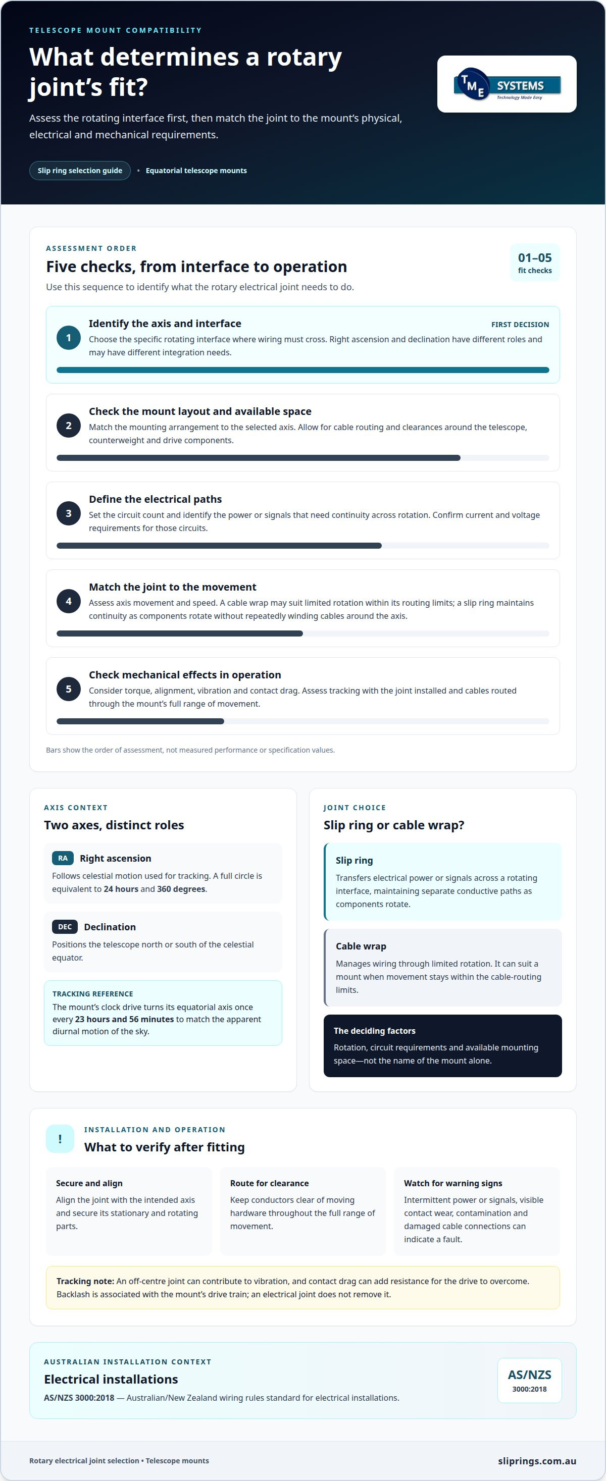
A rotary joint for an astronomical telescope mount is not a universal fit. Compatibility depends on which rotating axis needs an electrical path, the available space and the circuits that must cross the rotation. An equatorial mount has two axes, right ascension and declination, but a slip ring is relevant only where wiring must cross a rotating interface. Choosing a rotary joint for an astronomical telescope mount means matching it to that specific interface.
It makes sense to focus on the connector, but how it fits the mount matters just as much. A joint suited to one axis may not suit the other because the mounting arrangement and movement differ. The connector must also match the system’s electrical and mechanical requirements. When routing wiring across a telescope mount’s rotating interface, consider the circuits involved and the available mounting space.
This guide explains how right ascension and declination movement relate to rotary electrical joints, what to assess for physical and electrical compatibility, and how mount type affects the choice. It covers key engineering details, including circuit count, current, voltage, speed, mounting style and operating environment. You’ll have a clearer basis for deciding whether a rotary joint suits your telescope system.
Key Takeaways
- Identify which mount axis needs electrical continuity across rotation; the right ascension and declination axes can have different integration needs.
- Assess the joint against the telescope and mount layout, including available space, cable routing and mounting arrangement.
- Compare rotary electrical joints, slip rings and cable wraps by how each handles wiring as the mount moves.
- Define circuit count, current, voltage, speed and environmental requirements before settling on a configuration.
- Technical application consulting can help align these requirements with a suitable slip ring and mounting option.
Right ascension and declination axes
An equatorial mount has two rotational axes: right ascension and declination. Common rotary-joint problems include intermittent electrical connections, contact wear and contamination. Maintenance centres on inspection, clean connections and following the manufacturer’s instructions.
Rotary Joint Types
A rotary electrical joint transfers power or signals between stationary and rotating parts, allowing wiring to cross an axis without winding around it. For a telescope, the right arrangement depends on which moving section needs electrical continuity and how its cables are routed.
On an equatorial mount, right ascension follows the celestial motion used for tracking, while declination positions the telescope north or south of the celestial equator. A full circle of right ascension is equivalent to 24 hours and 360 degrees. The axes therefore have distinct roles, and a joint’s location must match the movement and wiring needs of the selected axis.
The mount’s clock drive turns its equatorial axis once every 23 hours and 56 minutes to match the apparent diurnal motion of the sky. A properly aligned mount can follow celestial objects using manual slow-motion controls or an electric motor. During astrophotography, equatorial tracking avoids image rotation in the focal plane. The joint must support the electrical connection required during that motion without obstructing the mount’s adjustments.
Failure Modes and Maintenance
Intermittent power or signals, visible contact wear, contamination and damaged cable connections are practical warning signs. A fault can interrupt a motor or another electrical circuit as the mount moves, affecting tracking or control. The effect depends on which circuit crosses the rotating interface and whether the problem occurs throughout movement or only at a particular position.
Follow the rotary-joint manufacturer’s instructions and the mount’s operating requirements for maintenance. Inspect accessible connections and cable routing for looseness, wear or interference throughout the full range of movement. Keep contact areas clean using only the specified method, and assess electrical continuity if a fault appears. Avoid assuming a standard inspection interval: operating conditions and the selected joint determine the appropriate maintenance plan.
Telescope and mount compatibility
Mount geometry and telescope payload determine where a rotary joint can fit and what movement it must accommodate. For powered electrical installations, AS/NZS 3000:2018 is the Australian/New Zealand wiring rules standard for electrical installations.
Installation aligns the joint with the intended axis, secures its stationary and rotating parts, and routes conductors clear of moving hardware.
Rotary Joints, Slip Rings and Cable Wraps
A slip ring transfers electrical power or signals across a rotating interface, while a cable wrap manages wiring through limited rotation. This distinction matters when a telescope mount tracks a celestial object and its wiring must move without snagging.
A cable wrap can suit a mount whose movement stays within its cable-routing limits. A slip ring maintains electrical continuity as components rotate, avoiding repeated winding of cables around the axis. The term rotary joint can describe the rotating connection; a slip ring is its electrical form. For a driven equatorial mount, the choice depends on rotation, circuit requirements and available mounting space.
Rotary Joint Specifications
Specifications show whether the joint suits the mount’s mechanical load and operating motion. Start with the telescope and accessories as a payload, then assess the mount’s available space and axis arrangement.
A refractor on an equatorial mount, for example, needs a joint positioned clear of the optical tube, counterweight and drive components. The joint’s torque must not place an unsuitable load on the mount drive. Its speed rating must suit the axis movement, while positioning accuracy depends on the mount and drive system as a whole. A Dobsonian mount presents a different layout; Newtonian telescopes with apertures from 12 to 18 inches are suited to Dobsonian mounting, but that does not by itself determine a rotary joint’s fit.
Effects on Vibration and Tracking
A rotary joint can affect mount behaviour if its installation creates mechanical interference or imbalance. This matters because tracking a celestial object relies on controlled movement, particularly during imaging.
A joint that is off-centre relative to its axis can contribute to vibration as the mount moves. Contact drag may also add resistance for the drive to overcome. Backlash, however, is associated with movement in the mount’s drive train; an electrical joint does not remove it. On a driven equatorial mount, assess vibration and tracking with the joint installed and the cables routed through the full range of movement. Interference or uneven resistance can affect tracking and image stability.
What types of rotary joints are used in telescope mounts?
A rotary electrical joint transfers power or signals between stationary and rotating sections. In a telescope mount, the relevant electrical type is commonly a slip ring. It maintains separate conductive paths across the rotating interface, allowing connected circuits to function as the mount moves. For example, one assembly may carry motor power and encoder signals.
Conventional contact slip rings use brushes and conductive rings to maintain electrical contact during rotation. Their circuit count, or number of independent paths, must cover each required power and signal line. Separate channels organise those circuits within one rotary unit. For a mount carrying a drive motor and position feedback, circuit planning must account for both functions, not just the motor connections.
Liquid metal rotary connectors are brushless rotary connectors that use a pool of conductive liquid metal to maintain electrical continuity. This contact approach eliminates wear and reduces noise. Unlike brush contacts, conductive liquid bridges the rotating connection instead of sliding brushes. For telescope electronics, assess whether the required circuits and signals suit the connector’s design, not simply whether it is brushless.
The joint’s physical form also affects integration. A through-bore slip ring has a hollow centre for mounting over a shaft or accommodating auxiliary components. A capsule slip ring has a compact, solid form for end-of-shaft mounting. On a telescope mount, shaft access, surrounding brackets and cable entry all influence which form fits the assembly.
These options address different electrical and mechanical requirements; no contact method suits every mount. A mount transferring power and control signals may need a different circuit arrangement from one carrying signals alone. The electrical load, signal type, rotation and mounting space therefore guide selection. A rotary joint is suitable when these details match the mount’s actual configuration.
Mount architecture provides another context for evaluating a rotary joint. Equatorial fork mounts are used for some mid-size professional telescopes with diameters in the range of 0.5-2.0 meters. Fork mounts are commonly used with catadioptric telescopes and other shorter optical tubes. These configurations do not, by themselves, specify a joint type; they help frame the physical arrangement in which the joint must operate. The relevant questions remain how the rotating and stationary sections meet, where cables can enter, and what electrical paths need to cross that boundary. A joint choice should follow those requirements rather than the mount label alone.
Equatorial platforms are often used with altazimuth-mounted amateur telescopes to enable tracking of the night sky. This is a different mount arrangement, so consider the rotary interface in the context of the assembly’s actual movement and available space. The March equinox occurs when the Sun crosses the celestial equator at the constellation of Aries, the zero point used for right ascension. That coordinate reference helps describe the sky, while joint selection depends on matching electrical and mechanical requirements. Keeping these distinctions clear prevents mount terminology from being mistaken for a rotary-connector specification.
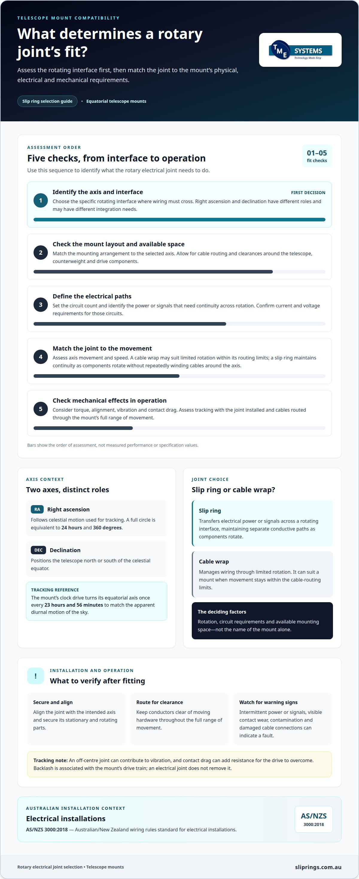
How do rotary joints differ from slip rings and cable wrap systems for telescope mounts?
“Rotary joint” describes a connection across rotating parts; a slip ring is an electrical rotary joint. This distinction helps when describing a telescope mount, because the required function matters more than the label. A mount carrying power and control signals across an axis needs an electrical path suited to those circuits and the axis movement.
A slip ring maintains electrical paths as one part rotates relative to another. For example, an equatorial mount could route motor power and position signals through separate circuits across a rotating interface. Circuit count means the number of independent paths available. The chosen arrangement must match the power and signals that actually cross that axis.
A cable wrap keeps conductors directly connected, guiding them around an axis as it moves. This avoids an electrical contact interface, but the cable’s movement and bend must suit the mount’s rotation. On a mount with limited movement, a managed cable loop may suit the layout. If rotation repeatedly twists or winds the cable, a slip ring offers a different routing approach.
The collector ring vs slip ring comparison matters: collector rings are heavy-duty rotary connectors designed for high current capacity, whereas standard slip rings are typically optimized for signal integrity and lower currents. This distinction matters when comparing equipment by name alone. An astronomical mount carrying control signals has different priorities from a system designed for high-current transfer. The connector must match the electrical load, not just the rotating mechanism.
Compare the options by tracing each circuit from the stationary structure to the moving assembly. A camera cable crossing a declination axis, for instance, may need a different solution from motor wiring at the right ascension axis. Then consider permitted movement, cable routing, mounting space and signal requirements. Cable wraps depend on managed cable travel; slip rings provide electrical continuity through rotating contacts. This comparison clarifies which design suits the mount’s actual movement and wiring plan.
What rotary joint specifications are needed for mount payload, torque, speed, and positioning accuracy?
Start with the telescope assembly, but distinguish payload support from electrical transfer. The mount supports the optical tube, camera and accessories; the rotary joint carries circuits across a rotating interface. For a refractor with a camera, record the circuits crossing each axis and the space available for the joint. This prevents an electrical component from being mistaken for structural support.
Electrical specifications should cover every circuit that crosses the joint. Record circuit count, current, voltage and whether each path carries power, control signals or data. For a driven mount, motor power and encoder feedback may need separate paths. Signal requirements matter too: a circuit suitable for one signal type may not suit another. Match each requirement to the equipment connected at both ends.
Mechanical specifications must suit the mount’s movement. Check the rotational speed rating against axis operation, and assess whether the joint’s operating torque adds load to the drive. Positioning accuracy is principally a mount and control-system requirement. However, poor alignment, interference or uneven resistance at the rotary interface can affect movement. Assess the joint in the assembled configuration, not as an isolated component.
- Payload: identify the telescope, camera and accessories supported by the mount.
- Torque: consider the joint’s resistance alongside the drive’s available torque.
- Speed: match the rotational speed rating to the mount’s actual axis movement.
- Positioning: account for alignment, mechanical clearance and signal paths used by the control system.
Mounting style shapes the configuration. A through-bore arrangement may suit an axis built around a shaft, while an end-mounted unit may fit a compact assembly. Cable entry, brackets and the full movement envelope affect placement. For a two-axis equatorial mount, assess each axis separately; one joint configuration need not suit both.
Technical application consulting can bring these details together in a final engineering review. A useful specification set includes the mount layout, electrical loads, signal types, movement profile, mounting constraints and environmental conditions. These inputs help define an application-specific configuration without treating payload, torque, speed and accuracy as interchangeable requirements.
Technical application consulting and slip ring engineering
Application engineering connects the telescope mount’s operating requirements with a suitable slip ring configuration. Technical application consulting helps define the electrical, mechanical and environmental details before selecting a design. This matters because the right ascension and declination axes may have different movement, mounting and circuit requirements.
The assessment starts with the system information that shapes selection. For each axis, the engineering review considers:
- the circuits required for power, control signals and data
- circuit count, current and voltage for each electrical path
- movement and rotational speed requirements
- available space, shaft arrangement and mounting style
- operating conditions and environmental requirements
For example, a mount may route drive power across one axis and sensor signals across another. Treating both interfaces as identical could overlook differences in circuit count or available space. The review maps each electrical path to its rotating interface and considers how the joint fits the assembly. This helps distinguish system-wide requirements from those specific to one axis.
Mounting options also shape the configuration. A through-bore arrangement may suit a shaft-mounted assembly, while an end-of-shaft position may favour another form. The application engineer considers cable entry, surrounding components and movement clearance alongside electrical requirements. This joined-up assessment reduces the risk of choosing a connector based on circuit needs alone.
For projects considering Prosper Rotation Slip Rings, technical application consulting helps relate the mount’s requirements to a suitable configuration. The same engineering process can assess available slip ring offerings against the application’s stated requirements through TME Systems Pty Ltd.
A final engineering review brings the key decisions together before selecting a configuration. It checks that circuit count, current, voltage, speed, mounting style and operating environment form a coherent specification. The review also identifies where the telescope’s two axes need separate configurations. The result is a defined technical basis for choosing a rotary joint for astronomical telescope mount suited to the mount’s electrical and mechanical arrangement.
TME Systems
TME Systems helps assess slip ring requirements for telescope mounts and match them to a suitable configuration. This is a practical next step when the axis, electrical circuits or mounting arrangement make selection unclear. The assessment considers the mount as a working system, rather than treating the rotary joint as an isolated component.
Technical application consulting brings the key requirements into one engineering view. The review can consider circuit count, current, voltage, signal type, movement, mounting style and operating environment. For a mount with separate right ascension and declination interfaces, each axis can be assessed against its own wiring and space constraints. This helps establish whether one configuration suits both interfaces or separate arrangements are needed.
TME Systems supplies Mercotac® connectors, Meridian Laboratory - ROTO-CON, BGB Innovation and Prosper Rotation slip rings. These product families address different strengths, allowing the right slip-ring technology to be matched to the application. Selection depends on the telescope system’s specifications, including how power or signals cross the rotating interface and how the joint integrates with the mount.
A useful engineering discussion starts with the mount layout and the circuits that must cross each rotating axis. Information about the telescope, accessories, drive system, available space and operating conditions helps establish the application requirements. TME Systems can then assess relevant slip ring options and identify a configuration suited to those requirements.
The final engineering review brings the selection criteria together before settling on a configuration. It considers electrical compatibility alongside mounting and movement, helping address potential conflicts such as restricted clearance or unsuitable cable entry. This is particularly useful when a standard arrangement does not fit the telescope mount’s physical layout, or when different axes have distinct requirements.
For an application involving Prosper Rotation Slip Rings or another suitable option, the next step is to discuss the mount’s requirements with TME Systems. Contact TME Systems to discuss your telescope mount application.
Frequently Asked Questions
What is a rotary joint in an astronomical telescope mount?
A rotary joint is the electrical interface that connects a stationary cable to equipment carried by a moving telescope assembly. Identify which side remains fixed and which turns, then map each conductor to its destination. For example, a camera may need separate power and data paths, while a control line serves the mount drive. This circuit map clarifies cable terminations and connection points before integrating a rotary connector.
How do you choose a rotary joint for an equatorial or alt-azimuth telescope mount?
Choose according to the mount’s tracking geometry and the electrical functions crossing each moving interface. An equatorial mount follows celestial motion around its aligned axis; an alt-azimuth system coordinates altitude and azimuth. For an alt-azimuth mount used for imaging, field rotation is a tracking consideration, not something a rotary joint corrects. Include control and imaging circuits in the design review to keep them routed through the intended axes.