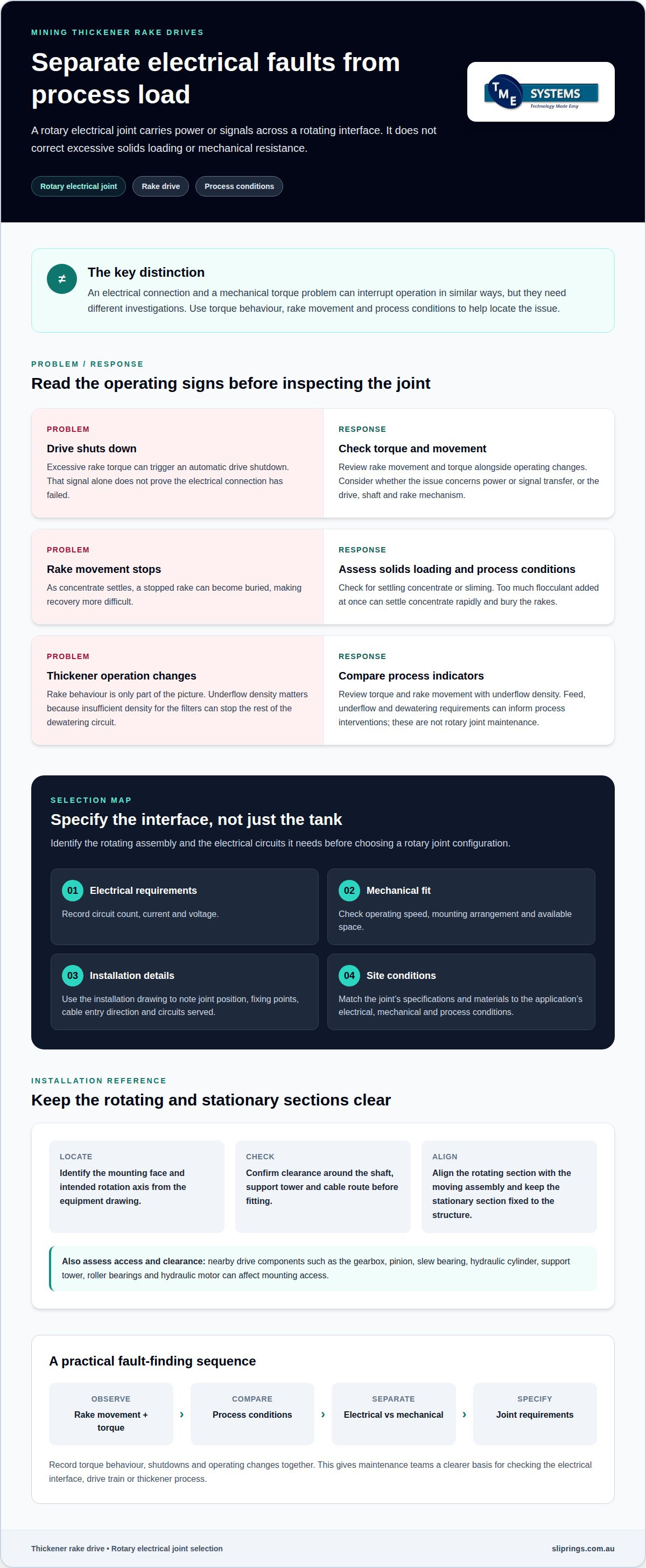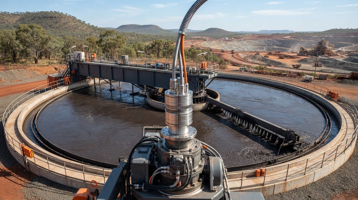
A rotary electrical joint can support a thickener rake drive, but it cannot correct a mechanical torque problem. A rotary joint for mining thickener rake drive applications is relevant when electrical power or signals must cross a rotating interface. Rake torque and movement still need close attention: a stopped rake can become buried as concentrate settles.
When reliability is at stake, it is easy to focus on the drive unit. Yet the rake mechanism, bearings, hydraulic equipment and electrical connections each have distinct roles. Identifying the component involved helps narrow the maintenance question and avoids treating an electrical connection as a mechanical fix.
This article explains how a rotary electrical joint fits into thickener and clarifier systems, which drive components affect operation, and what to consider when selecting a slip ring. It also covers how technical application consulting can help match circuit count, current, voltage, speed, mounting style and site conditions to the application.
Key Takeaways
- Use rake torque and movement as operating indicators; excessive torque can trigger an automatic drive shutdown.
- Know how the driveshaft, bearings, rake arms and drive unit work together to move settled solids towards the thickener centre.
- Map the rotating interface and the electrical circuits it needs to carry before selecting a rotary joint configuration.
- Match joint specifications and materials to the application’s electrical, mechanical and process conditions.
- TME Systems’ slip ring range and technical application consulting can help narrow the options for a thickener drive application.
Drive reliability and maintenance
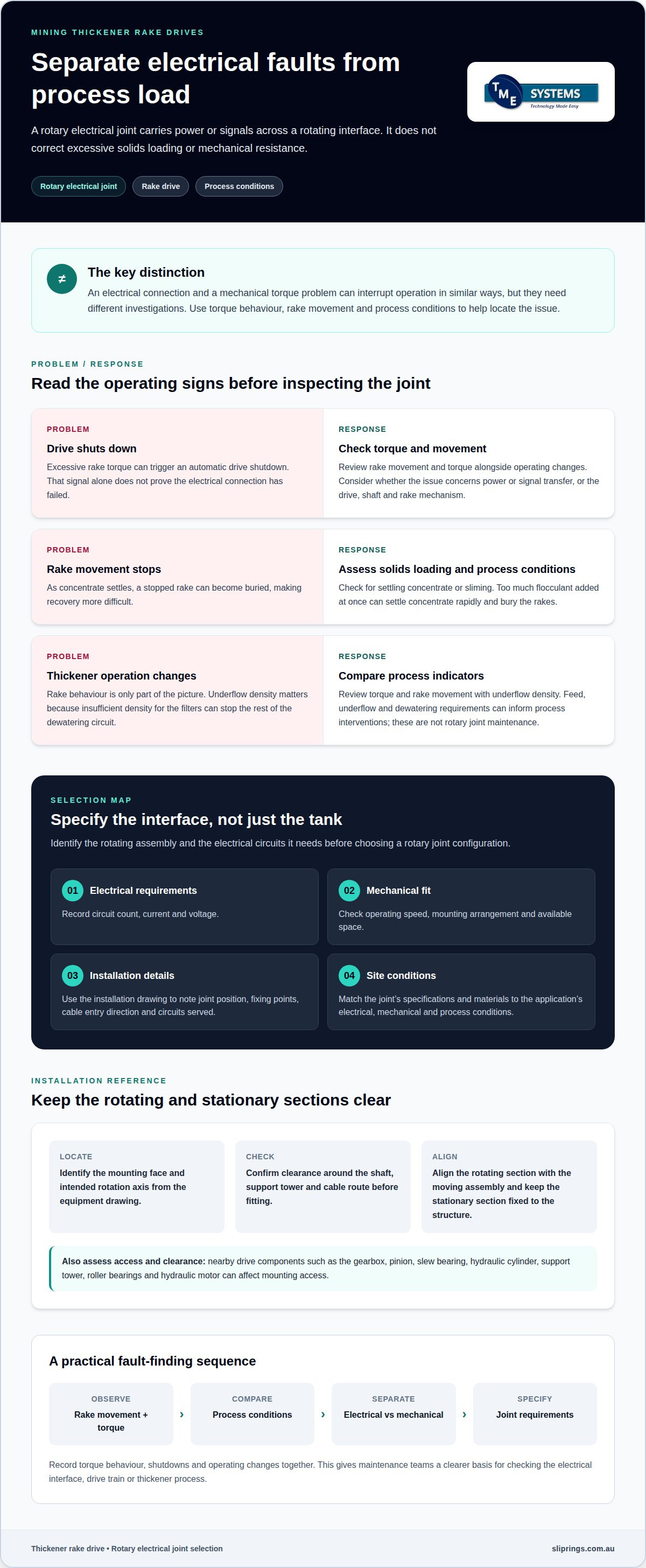
Thickener rake reliability depends on both the drive and the settling load. Rake torque indicates the load on the arms and helps operators decide when to lift them. A rake drive may shut off automatically if torque becomes too high. Treat a shutdown as an operating signal, not proof that the electrical connection has failed. A rotary electrical joint carries power or signals across a rotating interface; it does not correct excessive solids loading or mechanical resistance.
Operators need to monitor rake movement and torque closely. A stopped rake can become buried as concentrate settles, making recovery more difficult. During a circuit shutdown, operators may lift the drive shaft and rake arms to create room for settling mineral. This response relates to the thickener’s operating condition, not simply the state of its electrical components. At a nickel operation, a plant restart assessment identified a thickener drive as requiring major repair or replacement.
For Australian electrical installations, AS/NZS 3000:2018 is the Australian/New Zealand wiring rules standard for electrical installations. Site requirements include the joint’s electrical connection, mounting arrangement and operating environment. Installation planning must also address electrical and mechanical safety risks, including contact with electrical parts and unexpected movement of rotating or hydraulically lifted equipment.
Maintenance decisions should connect torque trends with process conditions. Operators also monitor underflow density, because insufficient density for the filters can stop the rest of the dewatering circuit. If the thickener begins to slime, possible operating responses include restricting or stopping feed, withdrawing more underflow, or adding flocculant. These are process interventions, not rotary joint maintenance.
- Review the operating condition: Compare rake movement and torque with underflow density. Look for a process change alongside any drive alarm.
- Assess solids loading: Check whether settling concentrate or sliming may be increasing resistance. Too much flocculant added at once can settle concentrate rapidly and bury the rakes.
- Separate electrical and mechanical symptoms: Examine whether the issue concerns power or signal transfer, or the drive, shaft and rake mechanism.
- Plan intervention around the circuit: Consider feed, underflow and dewatering requirements before changing thickener operation.
Maintenance planning for a rotary joint in a mining thickener rake drive should account for both the rotating electrical interface and the process load. A joint fault and a high-torque event can cause similar symptoms, such as interrupted operation, but require different investigations. Record torque behaviour, shutdowns and operating changes together. This gives maintenance teams a clearer basis for deciding whether the issue lies with the electrical interface, drive train or thickener process.
Thickener and clarifier components
Identify the thickener component and its function before specifying a rotary connection. A rake mechanism, drive unit and feedwell are related parts of the system, but each has a different role. Understanding their layout helps distinguish the equipment interface from the surrounding process components.
For an Australian thickener installation, the rotary joint configuration depends on the application’s electrical and mechanical requirements. Relevant selection details include circuit count, current, voltage, speed, mounting arrangement and operating environment. These factors define the equipment needed, rather than the tank type alone.
Rake drive and feedwell connections
The rake mechanism moves settled solids towards the tank centre for removal. Its components include a driveshaft, pickets, steady bearing, struts and tie rods, slide bearing, guide blocks, rake arms and blades. The arms angle upwards at their far ends, directing the bed towards the centre. Identify the rotating assembly and the electrical circuits it needs before deciding where to locate a rotary connection.
A feedwell has a different process role: it should mix gently so flocs form without breaking. Establish whether the feedwell rotates and carries electrical equipment. Assess the rake drive and feedwell as separate interfaces, even when they share the same thickener structure.
Replacement joint selection and sizing
For a replacement, start with the installation drawing and identify the joint’s position relative to the drive shaft and support structure. Record the mounting space, fixing points, cable entry direction and circuits served. Then compare these details with circuit count, current, voltage and operating speed. This approach defines a suitable configuration for the actual equipment instead of relying on appearance alone.
Consider nearby drive components when reviewing clearance. A thickener drive unit, typically above the tank, powers the rake mechanism. Related spares can include a gearbox, pinion, slew bearing, hydraulic cylinder, support tower, roller bearings and hydraulic motor. Note which parts affect access or mounting, without treating them as components of the rotary joint.
Installation and alignment procedure
Use the equipment drawing to identify the mounting face and intended rotation axis. Check clearance around the shaft, support tower and cable route before fitting the joint. Align its rotating section with the moving assembly and keep its stationary section fixed to the structure. This provides a clear reference for inspecting the installation.
After mounting, check that cables follow the planned route and stay clear of moving parts. Compare the installed position with the drawing, then record the configuration for future maintenance. If hydraulic equipment lifts the rake, account for its movement when checking cable clearance and joint access.
Clarifier and thickener layouts differ, so identifying components remains useful during replacement planning. Map the rake assembly, drive unit and feedwell separately, then use the relevant drawing and application details to define the connection. This keeps the rotary joint specification tied to its actual interface and the functions of process equipment distinct.
How does a rotary joint connect to a thickener rake drive and rotating feedwell?
A rotary electrical joint transfers power or signals between stationary wiring and rotating equipment. At a thickener, the connection depends on which assembly rotates and which circuits it needs. The rake drive and a rotating feedwell are separate interfaces. Map each independently before deciding where a joint belongs.
For a rake drive, trace the electrical path from the fixed supply or control equipment to the rotating assembly. The joint’s stationary side connects to fixed wiring; its rotating side connects to the equipment that turns with the shaft or drive. The drive unit is typically above the tank, while its driveshaft turns the rake mechanism below. Choose a mounting position that suits the actual arrangement, not simply the nearest convenient surface.
A rotating feedwell needs its own connection assessment. Identify whether it rotates independently, moves with another assembly or remains stationary. Then establish whether it needs electrical power, control signals or both. For example, if a rotating feedwell carries electrical instruments, the joint must serve those circuits and accommodate their movement. A feedwell with no electrical circuits does not, by itself, require an electrical joint.
Keep electrical transfer distinct from mechanical drive and process connections. A rotary electrical joint does not transmit torque to the rake, move the feedwell or carry slurry. The thickener drive powers rake movement; the electrical joint bridges rotating and stationary electrical paths. If the design also requires fluid transfer across a rotating boundary, treat it as a separate interface in the equipment layout.
Use a connection map to clarify the arrangement. Mark the fixed structure, each rotating assembly, and the equipment requiring power or signals. For the rake drive, include the drive unit, shaft and rake. For a rotating feedwell, identify its support and any instruments or actuators. This shows whether the project needs one joint or separate electrical connections for distinct rotating assemblies.
- Identify the rotation: Record which parts move together and which remain fixed.
- List the circuits: Separate power, control and signal paths for the rake drive and feedwell.
- Locate the interface: Choose a mounting point that bridges the stationary structure and rotating assembly.
- Check the route: Trace cable entry and exit paths through the full rotation, clear of the shaft, rake structure and other moving parts.
During layout review, compare the drawing with the installed thickener. A shaft-mounted joint may suit an accessible shaft interface, while a frame-mounted arrangement may suit another design. Confirm that the rotor follows the intended rotation and the stator remains fixed. This helps prevent cable restraint, interference or an incorrectly assigned connection.
For a rotary joint on a mining thickener rake drive, the connection is defined by the rotation boundary and electrical duty. Treating the rake drive and feedwell as separate assemblies makes the wiring path, mounting point and circuit purpose easier to specify.
What rotary joint specifications are needed for thickener rake drive service?
Specify the electrical duty, rotation, mounting arrangement and site conditions together. A joint carrying drive power needs a different circuit arrangement from one carrying control signals. Start with the equipment drawings and rake-drive connection map, then record each requirement against the intended rotary interface. This gives the selection a clear engineering basis.
Begin with circuit count, current and voltage. Circuit count means the number of independent electrical paths for power and signal transmission. Separate power circuits from control or monitoring circuits because their electrical duties can differ. Record each circuit’s operating current and voltage, then identify whether signals need uninterrupted transfer during rotation. Avoid sizing by connector appearance or a previous part number alone.
Next, establish the rotational speed rating and direction of movement. The rotational speed rating is the maximum permissible revolutions per minute without compromising performance. Match it to the rake-drive operating conditions, including changes during start-up or shutdown. Also record whether rotation is continuous or intermittent and whether the assembly reverses direction. These details affect contact design and the joint’s mechanical arrangement.
- Electrical duty: circuit count, current, voltage and the distinction between power and signal paths.
- Rotation: operating speed, direction, duty pattern and any movement during start-up or shutdown.
- Mounting: shaft dimensions, available envelope, fixing points and cable entry direction.
- Environment: dust, moisture, temperature, vibration and exposure to process chemicals.
- Integration: required cable routes, grounding arrangement and nearby hydraulic or mechanical components.
Mounting geometry determines whether the joint fits the rake-drive layout. A through-bore slip ring has a hollow centre for mounting over a shaft or accommodating auxiliary components. An end-of-shaft arrangement may suit a different interface. Compare available shaft space, fixing points and cable access with the equipment drawing. A mismatch can obstruct adjacent components or constrain cable routing.
Site conditions shape protection and thermal management. An IP rating defines protection against dust and water ingress, so specify the exposure around the joint rather than assuming conditions are uniform across the tank. Temperature affects allowable electrical loading; thermal derating reduces allowable current as ambient temperature rises. Consider heat from nearby equipment and the enclosure when reviewing current capacity.
For a thickener rake drive, the joint specification should describe the whole interface, not just its electrical ratings. Include mounting dimensions, cable entry, environmental exposure and maintenance access. Keep the data together in a selection schedule, then compare proposed configurations against each requirement. This can reveal conflicts early, such as limited shaft clearance, increased circuit demand or restricted access around the drive tower.
Finalise the specification against the actual installation drawing and the circuits being transferred. A clear schedule lets engineering teams assess suitability without confusing the rotary joint’s electrical role with the rake drive’s mechanical load.
Which rotary joint materials and seals suit abrasive mining slurry and harsh chemicals?
Select materials and seals based on the interface’s actual exposure. An electrical slip ring transfers power or signals; it does not carry slurry. A rotary fluid joint transfers liquid between rotating and stationary sections, so its seals contain the process medium. Confirm which device the thickener arrangement requires before selecting materials or specifying seals.
For a rake-drive slip ring, assess dust, moisture, washdown exposure, temperature, vibration and chemical contact around the mounting location. The enclosure and seals must suit those conditions and protect the electrical assembly. An IP rating describes protection against dust and water ingress, but does not establish compatibility with every process chemical or abrasive particle.
For a fluid rotary joint, start with the slurry or chemical composition and operating conditions. Identify the process medium, temperature range, pressure, flow path and whether particles can enter the seal interface. Abrasive solids can affect sealing surfaces differently from chemical exposure. A seal compound suited to one condition may not suit a combination of exposures.
- Identify the medium: distinguish water, slurry, cleaning fluids and chemicals that may reach the joint.
- Describe particle exposure: note whether abrasive solids contact the joint, enter a flow path or remain contained in the tank.
- Record operating conditions: capture temperature, pressure, rotation and any start-stop duty.
- Map exposure zones: separate the tank interior, external mounting area and washdown paths.
- Define seal function: specify whether the seal excludes contaminants or retains a process fluid.
These distinctions prevent a common specification error: treating a rotary electrical joint and a rotary fluid union as interchangeable. For example, a rake-drive slip ring may need environmental protection around its electrical contacts, while a separate fluid connection needs seals suited to the conveyed medium. The components may sit near the thickener, but their material requirements differ.
Build a materials schedule from the exposure map. List each wetted or exposed component, its contacting medium and the relevant operating conditions. Include seal locations, enclosure interfaces, cable entries and cleaning exposure. This helps the design review address chemical compatibility and abrasion at the correct surface, rather than assigning one material choice to the whole assembly.
During replacement planning, compare the existing joint’s condition with the recorded exposure. Look for wear, corrosion, swelling, cracking or leakage, then identify the affected component and its contact medium. A failed external seal on an electrical enclosure points to a different issue than wear at a fluid joint’s process seal. Record these observations to inform material selection.
For a thickener installation, specify materials only after separating electrical protection from process-fluid sealing. A clear exposure record helps engineers assess suitable housing and seal options for the actual duty, including abrasive contact and chemical compatibility.
TME Systems: Mercotac Slip Rings
TME Systems Pty Ltd can help match a rotary electrical connection to the thickener drive’s circuit and mounting requirements. Consider its range when specifying a new installation or reviewing replacement options. Mercotac Slip Rings are one option alongside Meridian Laboratory, BGB Innovation and Prosper Rotation Slip Rings. Selection depends on the application’s circuit count, current, voltage, speed, mounting style and environmental conditions.
Before discussing an application, gather the equipment drawing and the electrical and mechanical requirements for the rotating interface. This gives the assessment a practical basis and helps distinguish a slip ring requirement from a mechanical or fluid connection. To discuss your thickener drive application, contact TME Systems Pty Ltd or visit the Mercotac Slip Rings page.
Prepare the next engineering review
Before specifying a rotary joint for a mining thickener rake drive, bring the operating details together in a clear application record. Include the equipment drawing, electrical requirements, mounting dimensions and conditions around the rotating interface. This gives the engineering review a practical starting point and helps distinguish the required electrical connection from mechanical or process equipment.
TME Systems Pty Ltd supplies Mercotac Slip Rings, Meridian Laboratory Slip Rings and BGB Innovation Slip Rings. Its technical application consulting can help assess the application against circuit count, current, voltage, speed, mounting style and environmental requirements. Set out those details alongside the operating issue or planned replacement to keep the discussion focused on the actual thickener installation.
For an application discussion and the next step towards a suitable configuration, contact TME Systems Pty Ltd. Clear operating information can help move the selection forward with confidence.
Frequently Asked Questions
What is a rotary joint in a mining thickener rake drive?
In a mining thickener rake-drive assembly, the rotary joint is the electrical connection assigned to the rotating drive interface. For maintenance records, note its equipment tag, wiring termination identifiers and drawing reference. These details help teams match inspection findings to the correct assembly, particularly when a thickener has separate electrical connections for the rake drive and instrumentation. Keep its identification distinct from gearbox, bearing and hydraulic component records.
What are common rotary joint failure modes in thickener applications?
Common failure modes include contact wear, contamination, moisture ingress, loose terminations and damaged cables. Each can produce different evidence: contact wear may affect continuity, while a loose termination can cause intermittent operation. Record the observed symptom and affected circuit rather than treating every interruption as the same fault. Note whether the fault appears during rotation, start-up or a process change, as this context can help narrow the investigation.
How often should thickener rotary joints be inspected and maintained?
Use the joint manufacturer’s maintenance guidance and the site’s planned maintenance program to set inspection frequency. Include an inspection during scheduled shutdown work, and reassess after a fault, cable disturbance or change to the mounting arrangement. Track findings against the equipment tag so developing wear or contamination can be compared over time. Set the inspection interval according to the joint’s duty and site environment, rather than an arbitrary calendar period.