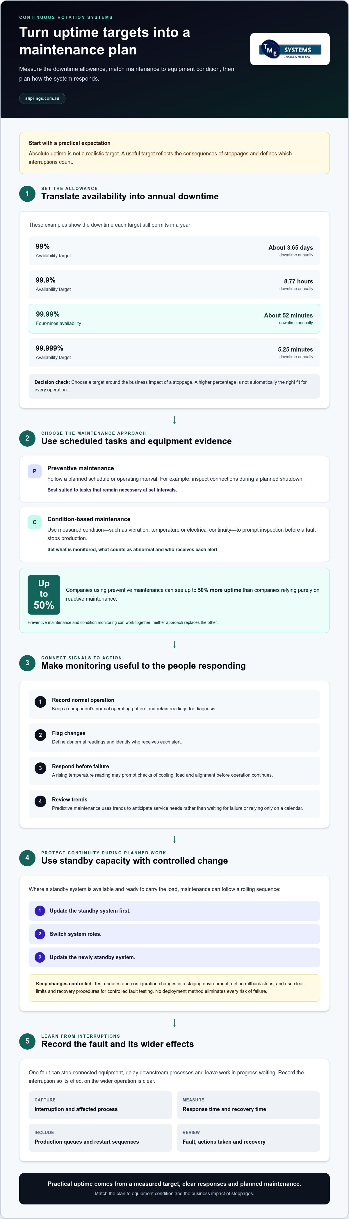
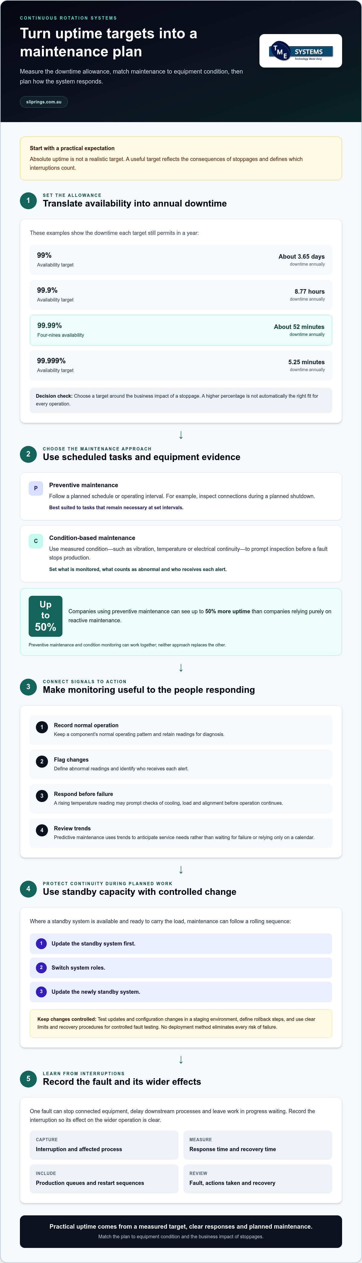
Absolute uptime isn’t a realistic target for a continuous rotation system. The practical answer to how to guarantee uptime in continuous rotation systems is to reduce avoidable failures and set a measurable availability target that reflects the consequences of stoppages. Even a 99.99% uptime target allows about 52 minutes of downtime annually.
That distinction matters when a rotating electrical joint is part of a production line: planned maintenance, component condition and system design all affect interruptions. A high uptime target may suit a process where stoppages have serious consequences, while another application may need a different balance between availability and maintenance effort.
This article explains common causes of unplanned downtime, compares preventive and condition-based maintenance, and shows how to set an uptime target based on business impact. It also covers operational risks and technical factors to assess in a continuous rotation system, helping you choose a practical target instead of relying on an arbitrary percentage.
Key Takeaways
- Translate an availability percentage into annual downtime to see what the target means for production continuity.
- Compare scheduled preventive maintenance with condition-based monitoring, then consider how standby systems can support maintenance without stopping the whole operation.
- Reduce operational and administrative risks with clear incident-response roles, documented recovery steps and regular system health checks.
- Set an uptime target around the business impact of a stoppage; a higher percentage is not automatically the right fit for every operation.
- Assess bearings, seals and lubrication against the equipment’s operating conditions, and match rotary electrical connections to the application’s requirements.
1. What actually causes unplanned downtime in industrial operations?
Unplanned downtime often begins with a component failure, but the initiating fault may lie elsewhere. A rotary electrical joint can lose continuity through wear, contamination, unsuitable loading or poor alignment. Bearings, seals, lubrication, electrical supply and control settings can also affect a rotating assembly. A fault in one part may stop connected equipment and interrupt production. For example, a brief signal interruption can halt a process that depends on continuous feedback.
Availability figures make the operational allowance clearer. A system at 99.99% availability has about 52 minutes of downtime annually, while 99.9% allows 8.77 hours per year. At 99.999%, the allowance is 5.25 minutes annually. A 99% target permits about 3.65 days per year. Four-nines availability, or 99.99%, still allows annual downtime, so teams should define which interruptions count.
The effects extend beyond the stopped machine. An interruption can delay downstream processes, leave work in progress waiting and disrupt delivery commitments. Repeated outages may also weaken customer confidence if orders are missed. Record the interruption, affected process, response time and recovery time. Include secondary effects, such as a production queue or restart sequence, to understand how one fault affects the wider operation.
Updates and deployment changes can also cause outages if a configuration change disrupts a control system. Test updates in a controlled staging environment before using them in production. If the system has a standby unit, a rolling deployment can update the standby first, switch operating roles, then update the newly standby unit. Hot patching applies changes to a running system, but still requires controlled testing and a recovery plan. No deployment method eliminates every risk of failure.
Which Australian standards and workplace safety rules apply to rotating machinery? AS/NZS 3000:2018 is the Australian/New Zealand wiring rules standard for electrical installations. Work should follow the site’s applicable safety procedures, including controls for hazardous energy and access to moving parts.
How should you safely inspect, repair and restart rotating equipment after a fault? Stop the equipment, isolate energy sources and prevent unexpected restart before inspection. Suitably competent personnel should carry out repairs. Afterward, check the work area and guards, then follow the site’s restart procedure. Monitor for abnormal vibration, noise or temperature, and document the fault and actions taken for future review.
2. What is the difference between preventive and condition-based maintenance?
Preventive maintenance follows a planned schedule, while condition-based maintenance responds to measured equipment condition. In a continuous rotation system, preventive maintenance might include inspecting connections during a planned shutdown. Condition-based monitoring might instead detect a change in vibration, temperature or electrical continuity, prompting inspection before a fault stops production. The first approach uses time or operating intervals; the second relies on evidence from the equipment.
Neither approach replaces the other. Preventive maintenance can cover tasks that remain necessary at set intervals, while condition monitoring helps identify developing faults between service periods. Companies using preventive maintenance can see up to 50% more uptime than companies relying purely on reactive maintenance. To make the approach useful, define which components are monitored, what readings count as abnormal, and who receives each alert.
Monitoring should link each signal to a response. For example, a rising temperature reading may prompt an operator to inspect cooling, load and alignment before continuing operation. A technical monitoring plan can record a component’s normal operating pattern, flag deviations and retain readings for diagnosis. Predictive maintenance uses these trends to anticipate service needs, rather than waiting for failure or relying only on a calendar.
Redundancy changes how maintenance affects availability. In a high-availability cluster, nodes can connect through two or more communication paths, and operation can transfer automatically to a standby node if the active one fails. A rolling maintenance sequence updates the standby system first, switches system roles, then updates the newly standby system. This can keep a service operating during planned work, provided the standby system is ready to carry the load.
Software patching needs similar controls. Test updates and configuration changes in a staging environment before deployment, and define rollback steps if performance degrades. Chaos engineering can test how a system responds to controlled faults, such as a simulated component or communication failure. Run these tests in a controlled setting, with clear limits and recovery procedures, rather than introducing faults into production without safeguards.
Automated maintenance can handle defined responses, such as restarting a service when an alert indicates it is nearing capacity. Automation still needs limits: record the trigger, action and outcome, and escalate repeated failures for technical review. Capacity planning adds another layer. Analyse resource use and forecast demand to avoid faults caused by an overloaded system. For rotating equipment, align monitoring thresholds and maintenance priorities with operating conditions and business impact. Technical application consulting can help match application requirements to a suitable rotary electrical connection.
3. Operational and administrative failure risks
Operational failures can start with a misaligned shaft, a loose electrical connection or an incorrect control setting. Administrative gaps create different risks: an obsolete configuration, an unreviewed software change or an unclear escalation path. Both can stop a rotating system. Regular health checks should review configurations, software versions and security patches, then record findings against the equipment and its operating history.
Electrical protection helps contain faults. A correctly selected circuit breaker interrupts current when a circuit experiences an overcurrent condition, limiting the effect to the protected part of the system. For example, a fault in one branch should not unnecessarily disable unrelated equipment. Protection must match the circuit design and equipment requirements. A breaker does not replace sound wiring, maintenance or safe isolation procedures.
Find single points of failure by tracing the path from the supply to the process. Check whether one power source, control panel, communication link or rotating connection can stop the whole operation. Redundancy can include duplicate power supplies and network paths, as well as standby equipment. Redundant communication paths and standby nodes can help maintain operations if a node fails.
Redundancy only helps if the alternate path works under operating conditions. Document how changeover occurs, which signals indicate a fault and how operators return to normal operation. Load balancing can spread application demand across systems, reduce single-system bottlenecks and allow maintenance on individual servers without taking the whole application offline. In industrial operations, ask whether a component failure can be isolated without stopping the entire production process.
Administrative controls determine how quickly people respond. An incident-response plan should identify who to notify, what actions to take and how to communicate with stakeholders for each alert type. A system outage or security breach should trigger an immediate response protocol. Keep rollback steps documented alongside update records so the team can restore the prior configuration if a deployment affects operation.
Alerts need an owner and a defined response, not simply an indicator on a screen. For instance, a capacity alert could trigger an automated script to allocate resources or restart a service nearing its limit. After resolving an alert, analyse the incident’s root cause and record actions that prevent recurrence. A documented 24x7 engineering rota is one operational consideration for high availability, but coverage must align with the organisation’s response plan. Missed alerts can delay production recovery and disrupt commerce through late orders or interrupted supply.
4. Choosing an uptime target based on business impact
Set the target according to the consequences of an outage, not a round-number preference. Map the rotating system to the applications and production stages it supports. If a rotary electrical joint stops a critical process, identify what other equipment stops, whether work can continue elsewhere and how quickly output must recover. This impact map shows which events justify a higher availability target. Planning how to guarantee uptime in continuous rotation systems starts with understanding these operational effects.
Compare candidate targets against the reliability measures each requires. For example, a 99.5% target and a 99.99% target represent different levels of required system reliability: a system targeting 99.99% must be 50 times as reliable as one targeting 99.5%. The higher target may suit an operation where interruptions affect essential production stages, while a lower target may fit processes with workable alternatives.
Use a consistent measurement period and define what counts as downtime. Calculate availability by dividing operational time by the total time under consideration, then multiplying by 100. Record planned shutdowns separately from unplanned outages, and state whether partial operation counts as available. For example, a line that runs while one application is unavailable may not have the same business impact as a complete production stop.
Make the target actionable by defining response and recovery expectations alongside the percentage. Specify who receives an alert, what action follows and which process takes priority. Without an agreed response plan, a target can leave the team uncertain during an outage. Document the measurement window, outage events, exclusions and reporting method so operations and management assess performance consistently.
Compare the target with actual incident records before adopting it. Group unplanned events by cause, duration, affected application and production impact. A recurring connection fault may call for a component or system design review; an isolated event with limited impact may instead inform maintenance planning. This evidence helps distinguish a genuine availability requirement from an aspirational figure that does not affect business decisions.
Review the target when the process changes. A new production stage, tighter delivery commitment or reduced ability to switch to another line can increase the impact of downtime. An alternate process, by contrast, may reduce the consequences of an outage. Record changes and revisit the availability target during the next engineering review, rather than carrying forward an assumption that no longer fits operations.
To decide how to guarantee uptime in continuous rotation systems, choose the target that keeps the defined business impact within acceptable limits. A 99.5% target may suit one operation, while a process with severe outage consequences may require a higher reliability design. Set the target with operations, engineering and management, then connect it to measurable availability, documented response actions and reviewable outage records.
5. How to choose bearings, seals and lubrication for 24/7 rotating equipment?
Start with the equipment’s operating conditions, not a preferred bearing or lubricant brand. Record shaft speed, radial and axial loads, alignment, ambient temperature, contamination and duty cycle. For example, a dusty plant environment places different demands on seals than a clean, enclosed production area. These inputs inform the bearing arrangement, sealing method and lubrication approach.
For bearings, match the load direction and magnitude to the application. Radial loads act across the shaft; axial loads act along it. Misalignment, vibration and changing loads can affect bearing performance, so include them in the design review. Check how the bearing is mounted and supported, and whether the surrounding structure maintains alignment as the equipment heats during operation.
Seals must suit both the material being retained and the contaminants being excluded. Consider exposure to dust, moisture, washdown, process fluids and temperature changes. A seal that limits ingress can also affect friction and heat generation. For a rotating shaft exposed to abrasive particles, assess the seal arrangement alongside shaft surface condition and operating speed. The seal should protect the assembly without creating an unsuitable operating load.
Lubrication requirements depend on bearing type, operating speed, load, temperature and compatibility between the lubricant and nearby materials. Too little lubricant can increase friction and wear; excess lubricant can also contribute to heat or leakage. Follow the equipment manufacturer’s lubrication instructions, including the specified product and application method. Record each lubrication task so technicians can spot missed intervals, leaks or changes in consumption.
For continuous duty, set inspection criteria around observable changes. Monitor bearing temperature, vibration, noise and lubricant condition against the equipment’s normal pattern. Rising temperature accompanied by increased vibration may indicate a developing mechanical issue, while a visible leak can point to a seal problem. Record readings under comparable operating conditions, then investigate sustained changes rather than relying on a single observation.
Plan service access before installation. Confirm whether guards or nearby components obstruct inspection, lubrication points or bearing replacement. A layout that allows safe access can make routine checks more consistent and reduce the chance of deferred work. Include the shaft, coupling, housing and connected rotary electrical joint in the same assessment, since misalignment or heat in one part can affect adjacent components.
Keep maintenance records practical: note operating conditions, inspection findings, lubrication actions and component changes. Use these records to refine inspection priorities and identify recurring faults. Bearings, seals and lubrication support mechanical rotation; electrical continuity through a rotating interface needs its own application-specific assessment, including load, speed, circuit count and mounting arrangement.
TME Systems: Mercotac Slip Rings
TME Systems can help match a slip ring to the electrical and mechanical demands of a continuous rotation application. Its range includes Mercotac Slip Rings, Meridian Laboratory Slip Rings, BGB Innovation Slip Rings and Prosper Rotation Slip Rings. Technical application consulting can help assess circuit count, current, voltage, operating speed, mounting style and environmental requirements when selecting a rotary electrical connection.
Bring the application details together: the signals or power that must cross the rotating interface, how the unit mounts and the conditions it will face. These details give the selection process a practical basis and help align the slip ring with the system’s uptime requirements.
Contact TME Systems to discuss your application, or visit sliprings.com.au.
Turn your uptime target into an engineering brief
The next step is to connect the availability target to the rotating interface’s actual operating demands. Document the required power and signal paths, mounting arrangement, rotation conditions and environment. This gives engineering and operations a shared basis for assessing component suitability and reviewing the design as the application changes.
A practical approach to how to guarantee uptime in continuous rotation systems is to treat the target as a design and maintenance objective, not an absolute promise. Use operating records to identify recurring interruption patterns, then bring those findings into the next equipment review. This turns an uptime goal into decisions about system requirements, monitoring and component selection.
TME Systems offers Mercotac Slip Rings, Meridian Laboratory Slip Rings and BGB Innovation Slip Rings. Its technical application consulting can help relate your application requirements to a suitable rotary electrical connection. Bring relevant operating conditions and interface requirements into the discussion.
Contact TME Systems to discuss uptime and take the next step towards a target grounded in your application.
Frequently Asked Questions
Can uptime ever be truly guaranteed in rotating equipment?
No equipment design can rule out every possible interruption. A useful uptime commitment defines the operating window, the functions that must remain available and how exceptions are recorded. For example, decide whether reduced-speed operation counts as available when full production requires a specified speed. Clear boundaries make performance reviews more meaningful and help engineering teams assess whether the target still suits the process.
What actually causes unplanned downtime in industrial operations?
Unplanned downtime occurs when a fault interrupts a process that depends on the equipment. The first alarm or component noticed may not reveal the root cause. For instance, a control alarm during rotation could follow a supply fluctuation or intermittent signal. Preserve the event sequence, machine state and alarm record before resetting the equipment. These details help investigators distinguish the trigger from its downstream effects.
What is the difference between preventive and condition-based maintenance?
Preventive maintenance schedules work in advance; condition-based maintenance prompts action when measurements or inspections indicate a change. For example, a technician might inspect a connector during planned service, while a shift operator reports an intermittent signal that warrants an earlier assessment. A maintenance plan can combine both methods by assigning routine checks and stating which observed changes require escalation.
What are the main causes of downtime in continuously rotating machinery?
Causes can include wear, contamination, unsuitable operating loads, alignment changes and interruptions in power or control signals. The pattern of symptoms helps narrow the investigation. A fault that appears only in a particular operating mode, for example, directs attention to that mode’s load, movement or control sequence. Compare affected conditions with normal operation before replacing components, so corrective action addresses the actual failure mechanism.
What preventive maintenance schedule is recommended for continuous rotation systems?
Build the schedule around the equipment manufacturer’s instructions and the machine’s duty and environment. Assign each task to a role, state how findings are recorded and define what triggers escalation. A handover record can capture changes in sound, visible contamination or unexpected interruptions between formal service tasks. This gives the maintenance team useful context and helps keep inspections consistent across shifts.
What redundancy and backup strategies improve uptime in rotating systems?
Choose a backup strategy based on the function that must continue. A compatible spare rotary assembly may support a planned component exchange, while a bypass arrangement may suit a process that can safely operate without one function. Confirm how the alternate arrangement connects to the machine and document its changeover procedure. A backup that cannot be fitted or operated correctly during a fault will not provide practical continuity.
How do you calculate uptime, availability and MTBF for rotating machinery?
Availability is operational time divided by total time in the measurement period, multiplied by 100. MTBF, or mean time between failures, is total operating time divided by the number of failures recorded. Uptime describes the period the equipment operates according to the chosen definition. Keep the observation window and failure-counting method consistent, and record operating hours separately from calendar time.
How can Australian operators assess the operational impact of downtime?
Track the production stage affected, interruption duration, any backlog created and the time needed to return to normal output. Note whether another line or process can absorb the work, and whether delayed output affects later shifts or delivery commitments. Reviewing these measures together shows which interruptions cause the greatest operational disruption and helps prioritise engineering attention according to their effects on the process.