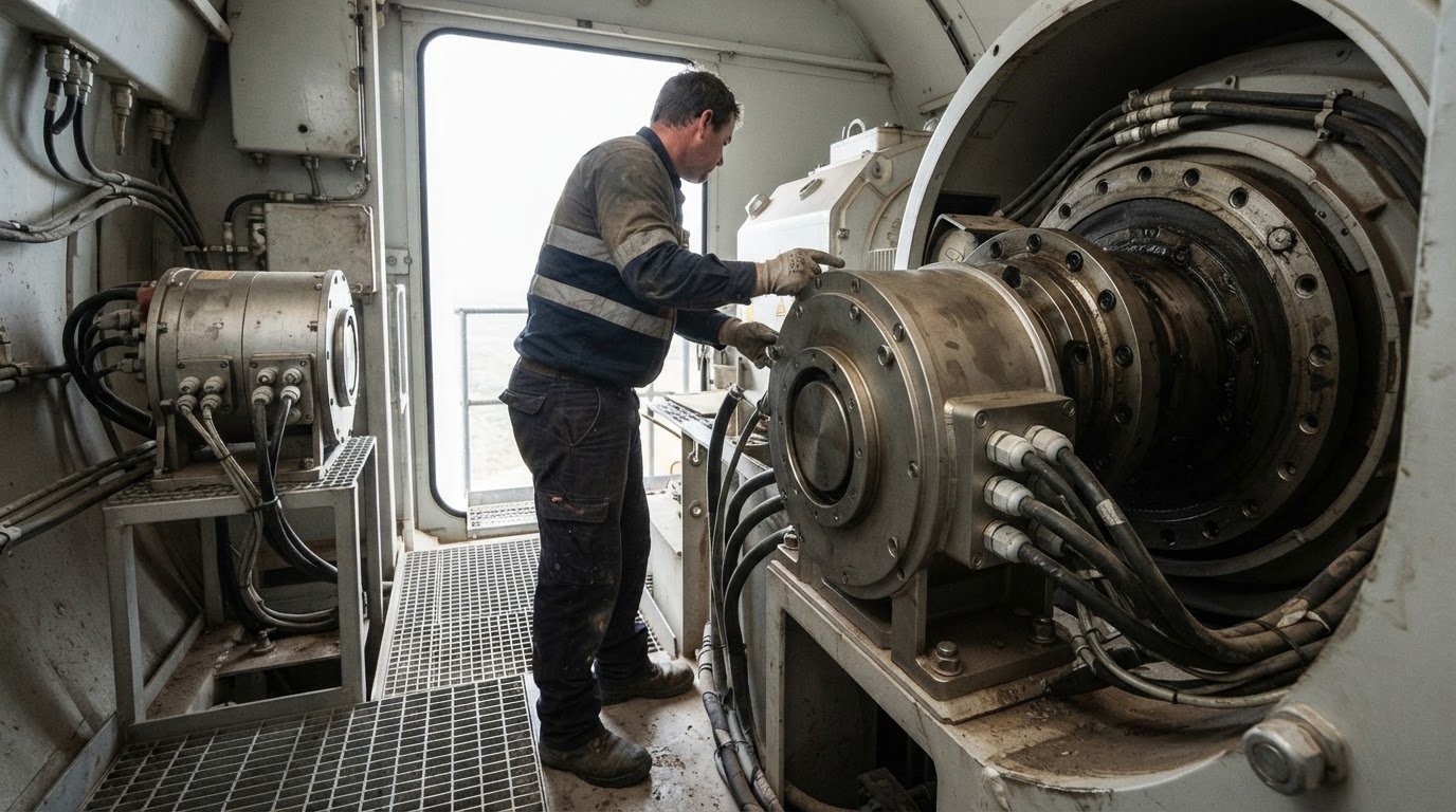
A production line can stop because one failed component interrupts the machinery around it, even when other equipment remains serviceable. Understanding how to de-risk single points of failure in rotating machinery starts with identifying components that have no practical backup, parallel capacity or bypass, then assessing the operational consequences if they fail. A rotary electrical connection can also become a dependency when its failure interrupts power or signals to a rotating assembly.
A practical risk review maps dependencies across the machine and its operating process, then weighs design resilience against mitigation. Redundancy or a bypass may limit the impact of failure; preventive maintenance can reduce exposure, while correctly selected critical spares can shorten recovery. Use downtime and production impact to prioritise where these measures matter most. The following sections explain how single points of failure arise, how to assess resilience and mitigation options, and what to consider when selecting slip rings for rotating machinery.
Key Takeaways
- Map which components can stop the whole process, including rotary electrical connections with no practical backup or bypass.
- Assess resilience by considering redundancy, parallel capacity and alternative routes through the system.
- Combine preventive maintenance, predictive monitoring and recovery planning to reduce the likelihood and impact of equipment failure.
- Prioritise critical spares by weighing failure consequences, repair time and the production time a spare could help recover.
- Match a slip ring to the application’s circuit count, electrical requirements, rotational speed, mounting style and operating environment.
What is a Single Point of Failure?
A single point of failure is a component whose failure stops the entire system. On a production line, an asset becomes a single point when its breakdown halts production and no backup, parallel buffer or bypass can keep work moving. The key test is functional: can the process continue if this component stops?
Identify potential failure points by tracing how the machine, its controls and connected equipment depend on one another. A pump, for example, may rely on a motor, coupling, bearings, lubrication and control signals. If one failed component stops the pump and there is no alternative route, it can become a bottleneck in the production network.
Review Overall Equipment Effectiveness (OEE) records alongside machine-level stoppage durations and lost output. A delay at a filler, for example, has a different impact if downstream equipment can continue operating than if the whole line stops. Match each stoppage timestamp to the affected asset, duration and lost production to identify dependencies.
OEE can show when a cycle delay occurred, but may not reveal its cause. Timestamped footage can help reliability engineers investigate the event at the machine. Self-diagnostic alarms and condition-monitoring data add context, while root-cause analysis can distinguish a failed part from contributing issues such as misalignment or poor installation.
Failure Mode and Effects Analysis (FMEA) gives teams a structured way to examine each component. Record its possible failure mode, the local effect and the effect on the overall process. A bearing defect may progress from vibration to a machine stoppage; a control fault may stop several connected assets. Systems analysis helps expose these dependencies before failure occurs.
Australian requirements depend on the equipment and installation context. AS/NZS 3000:2018 is the Australian/New Zealand wiring rules standard for electrical installations; assess reliability and maintenance risks separately against the machinery’s operating and site requirements.
Redundancy can still fail if supposedly separate equipment shares a utility, control system or other dependency. One power supply could disable both the primary and standby machines. Human error can also undermine a backup if procedures, changeovers or alarms are unclear. Include shared services and operating tasks in the failure analysis.
For rotating machinery, assess mechanical, electrical and process dependencies together. Shaft misalignment can contribute to bearing defects, while pump cavitation can disrupt flow. These are different failure mechanisms, but either can stop an asset with no effective alternative. Mapping each failure path clarifies where a redundant component, bypass or targeted investigation could reduce exposure.
Resilience in system design and operations
Resilient design limits the effect of component failure on production. Audits and standby testing reveal whether backup arrangements can support actual operations.
Redundancy Strategies for Rotating Equipment
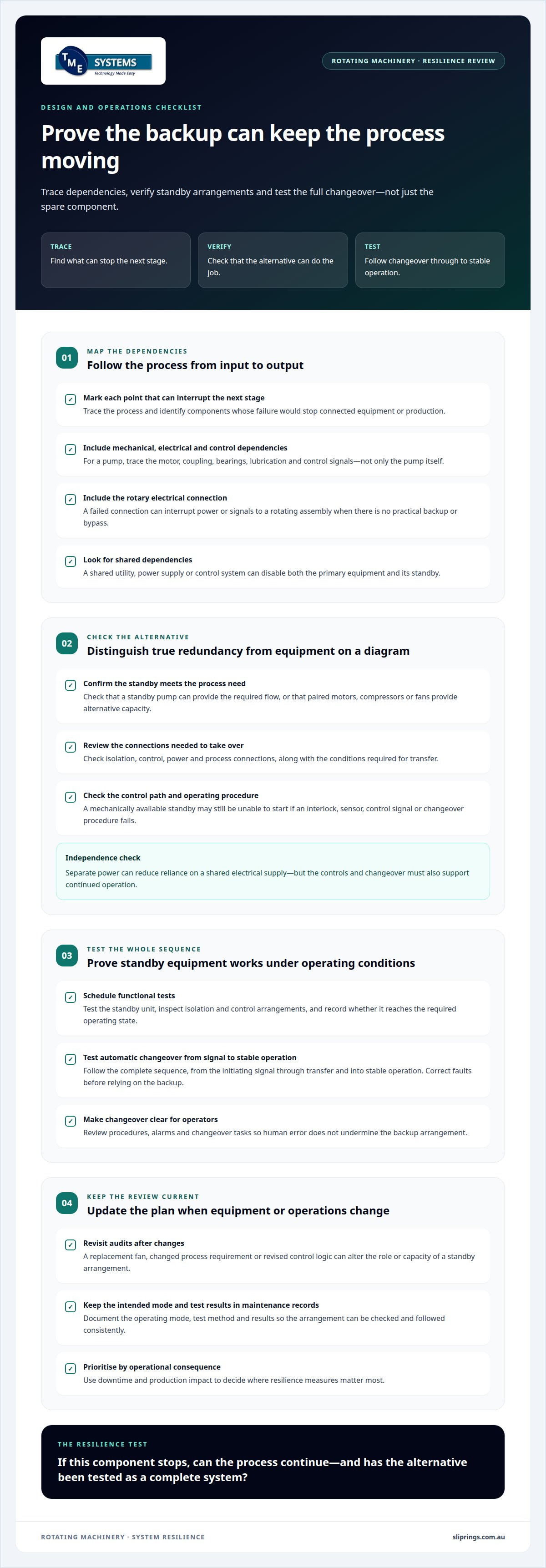
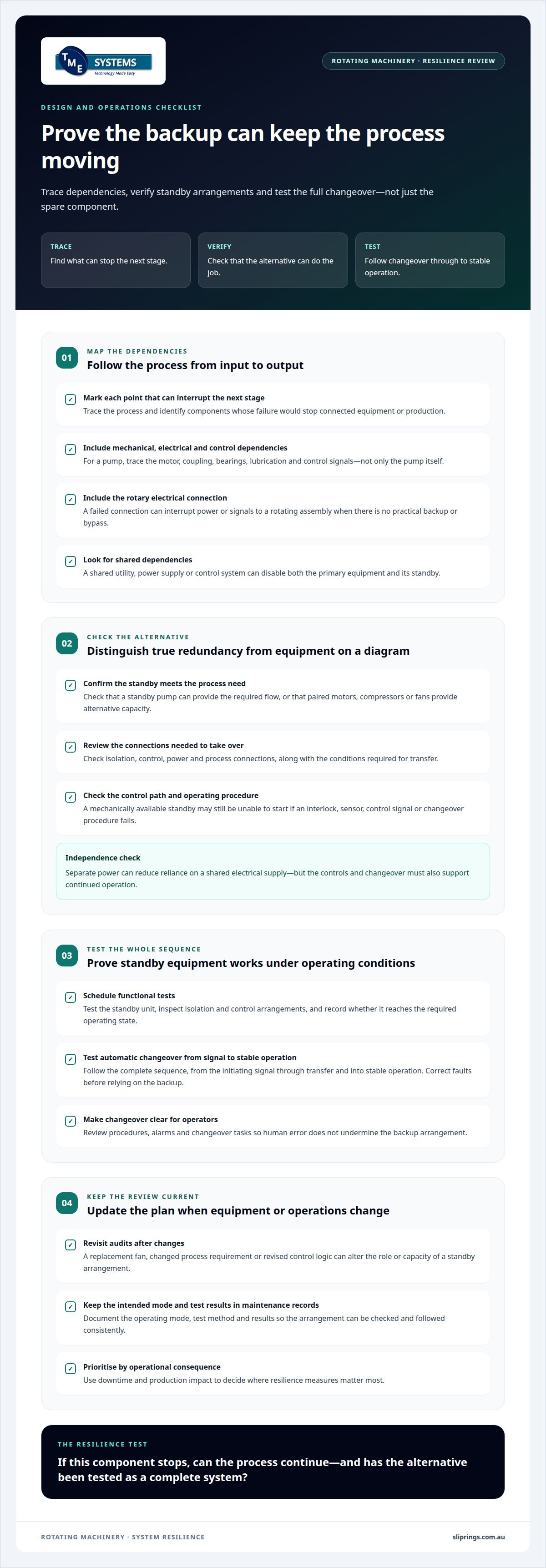
Redundancy provides an alternative component or route so a failure need not stop the process. A standby pump can take over the required flow; paired motors, compressors or fans can provide alternative capacity. The design must account for how equipment connects to the process, including isolation, control and changeover. Otherwise, the backup may not perform its intended role.
Verifying Standby Equipment and Changeover
Verification tests whether standby equipment and its changeover system work under operating conditions. A maintenance plan can schedule functional tests, inspect isolation and control arrangements, and record whether the standby unit reaches the required operating state. Test automatic changeover as a complete sequence, from the initiating signal to stable operation. Review the results and correct faults before relying on the equipment during a failure.
System audits can reveal bottlenecks that equipment lists miss. Trace the process from input to output, then mark each component whose failure interrupts the next stage. A series arrangement is especially exposed: if a motor, coupling or driven pump stops, the connected process may stop too. Assess the consequence of each failure, the alternative routes available and how quickly operations can recover.
Include operating procedures and control logic in the assessment. A standby pump may be mechanically available but unable to start if its interlock, sensor or control signal fails. For each backup, record its power source, control path, process connection and the conditions required for transfer. This systems view distinguishes true redundancy from equipment that only appears independent on a diagram.
Independently powered systems can reduce reliance on a shared electrical supply, provided their controls and changeover arrangements also support continued operation. Assess whether a standby motor can start when the primary supply or control path is unavailable. Consider the entire sequence, not just the motor: power, command signal, valves or dampers, and the equipment receiving the output.
Review audit findings whenever equipment, process requirements or control logic change. A replacement fan or revised operating sequence can alter the capacity or role of a standby arrangement. Record the intended operating mode, test method and results in maintenance documentation so operators can follow the same process. This makes resilience an ongoing part of operations, not a one-off design decision.
Where rotating machinery also transfers electrical power or signals across a moving joint, include that interface in the design review. Prosper Rotation slip rings are relevant when assessing a slip ring for a rotating application.
A multi-pronged mitigation approach
Effective mitigation combines equipment selection, maintenance and recovery planning. Together, these measures show how to de-risk single points of failure in rotating machinery by addressing both failure causes and consequences.
Selecting and Sizing Standby Equipment
Standby equipment is an alternative asset configured to maintain a critical service when primary equipment fails. Select and size it against the process requirement, including the required flow or output, operating conditions and system connections. For example, a standby pump must meet service demand, not simply match the installed pump’s nameplate; industrial pumping specialists such as Water Services, Inc. emphasise sizing against hydraulic conditions and duty points. Its isolation and changeover arrangements must also support the intended duty.
For a compressor or fan, consider whether the standby unit can meet required pressure or airflow under expected operating conditions. Assess the consequences of partial capacity as well as a full shutdown. A backup that cannot sustain the critical process may still reduce disruption, but it does not provide full replacement capacity. Document the service requirement and the standby unit’s role.
Selection should also account for how the standby asset starts and connects. Check that its power, controls and process interfaces allow it to operate when the primary unit is unavailable. A motor in storage, for example, is not an immediate backup if it must first be installed or aligned. Critical spares can support recovery when a complete standby unit is impractical.
Maintenance to Reduce Common-Cause Failures
A common-cause failure occurs when one condition disables both primary and redundant equipment. Separate maintenance tasks and inspect each asset independently to reduce the chance that the same error or missed defect affects both units. A preventive maintenance plan should address components and operating conditions that could compromise the shared service.
Maintenance practices can include checking lubrication, alignment, vibration and control functions on each machine. Predictive analytics can help identify developing faults before they disable a primary unit and its backup. Record findings against each asset; similar vibration changes across paired pumps, for example, may point to a shared installation or operating issue.
Make maintenance procedures specific to each unit and record completed work, defects and corrective actions. If both fans receive the same incorrect adjustment, redundancy may offer no protection. A supervisor can review procedures and compare operating data after maintenance to identify repeated errors before the equipment is needed.
A broader mitigation plan considers what happens after a fault is detected. Document the changeover sequence, assign responsibility for decisions and keep recovery instructions accessible to operators. Preventive maintenance and predictive analytics address equipment condition; clear procedures help people act on warnings and restore service. Together, these measures help teams decide how to de-risk single points of failure in rotating machinery while reducing exposure and supporting recovery.
Review the plan whenever process demand, equipment configuration or operating conditions change. A standby pump selected for one duty may no longer meet requirements after a process modification. Reassess its capacity, interfaces, maintenance needs and recovery role to keep the backup aligned with the critical function.
Assessing downtime and critical spares
Use lost operating time to compare equipment failures and assess where a spare could shorten recovery. Record how often an asset stops, how long each repair takes and how much production time is affected. Keeping these measures separate helps distinguish frequent, brief interruptions from less frequent failures that hold up a line longer.
In a worked filler example, the production line runs for 6,000 hours a year. The filler has 15 failures a year, and each repair takes 3 hours. Together, those failures account for 45 lost production hours a year. This baseline links failure frequency and repair duration to the machine’s effect on operations.
Next, compare the baseline with a specific recovery measure. In the example, a critical-spares kit reduces repair time to 1 hour. Across the filler’s failures, that change saves 30 production hours. The comparison focuses on restored operating time, rather than assuming that buying a spare automatically improves reliability.
Assess whether each proposed spare addresses the failure mode responsible for lost time. Record the affected component, repair steps and time needed to return the machine to service. Consider whether the part is compatible with the installed equipment, can be stored appropriately and is accessible to the people doing the work. A part that cannot be fitted as intended will not deliver the expected recovery benefit.
Compare a spare with other responses to the same disruption. Maintenance may prevent some failures, while an alternative route may allow production to continue. The decision should reflect the machine’s role, repair requirements and how strongly production depends on it.
After introducing a spare, track actual repair durations against the original 3-hour baseline. If repairs take longer than expected, examine whether access, diagnosis or installation is delaying the work. If the same failure continues, the spare may speed replacement without preventing recurrence. Use the updated records to refine maintenance plans and spare selection.
Set stock quantities according to the asset’s failure history, replenishment requirements, repair process and the number of machines that share compatible parts. Review quantities when equipment changes or usage patterns shift. This keeps spare inventory responsive to operational evidence, rather than relying on a static list that may no longer reflect production needs.
Definition and types of single points of failure
Defining a Single Point of Failure
For an engineering review, define the process boundary before classifying a dependency. A packaging cell, for example, may include machinery, control logic and the material-handling steps needed to produce a finished unit. The same component may be critical within that boundary but less critical across a wider site with another production route.
Describe the failure state precisely. A machine may stop completely, run below required capacity or fail to restart after a planned shutdown. These outcomes have different operational effects. Recording the affected function, operating state and recovery condition prevents the assessment from treating every fault as identical.
Distinguish the initiating fault from the point where its effect becomes visible. A drive fault might first appear as a production interruption at a downstream station. Tracing the sequence helps maintenance and engineering teams identify where detection, isolation or process design could limit the impact.
Types of Single Points of Failure
One useful classification is by propagation pattern. A local dependency affects one machine function; a cascading dependency carries disruption into later process stages; and a latent dependency remains unnoticed until another event exposes it. These categories help teams describe how a fault develops, rather than relying only on the component’s name.
A capacity dependency exists when the remaining equipment cannot meet the required duty after one unit becomes unavailable. A process may continue at reduced throughput but still fail to meet production requirements for a particular operating period. Record the acceptable output threshold so the assessment captures partial loss of function, not just complete shutdown.
An interface dependency lies between parts of a system that are otherwise serviceable. A mechanical coupling, data exchange or process hand-off can prevent two assets from working together, even when each passes its own inspection. Review the connection’s role and the failure indications available to operators.
A latent dependency is a weakness that becomes apparent only in a specific operating state, such as restart or a change in duty. Identify those states in the assessment and consider how the fault would be detected. The classification should guide what evidence is recorded and which operating scenarios receive attention.
Use these categories as shared vocabulary across maintenance, operations and engineering. A clear label links the observed failure pattern to its process effect, making risk registers and corrective actions more useful. Record the system boundary and operating assumptions alongside the classification so later reviews interpret the dependency consistently.
TME Systems
TME Systems helps Australian teams assess slip ring requirements when a rotary electrical connection could affect machinery reliability. Its technical application consulting supports selection based on circuit count, current, voltage, rotational speed, mounting style and environmental requirements. This is useful when a slip ring is part of a machine’s critical operating path or a replacement must suit an existing application.
TME Systems supplies Mercotac Slip Rings, Meridian Laboratory Slip Rings, BGB Innovation Slip Rings and Prosper Rotation Slip Rings. The right option depends on the application’s electrical and mechanical demands, not the product name alone. Sharing the operating requirements and installation context helps focus selection on compatibility with the rotating equipment and its role in the system.
Contact TME Systems to discuss slip ring requirements for your rotating machinery application.
Turn the risk assessment into an engineering decision
Turn identified dependencies into a clear application brief. Record which rotating assembly is affected, what electrical paths it needs and how its operating environment may influence component selection. This gives engineering discussions a defined purpose and helps align the chosen rotary connection with the machine’s actual duty.
For teams considering how to de-risk single points of failure in rotating machinery, TME Systems provides technical application consulting for slip ring selection. Its range includes Mercotac Slip Rings, Meridian Laboratory Slip Rings and BGB Innovation Slip Rings. The appropriate option depends on the application’s circuit count, current, voltage, speed, mounting style and environmental requirements.
Bring those operating details into the discussion when a slip ring forms part of a critical machine function or a replacement must suit an existing assembly. A focused review can help clarify the requirements before a selection is made. Contact TME Systems to discuss machinery risk and take the next step towards a better-defined application.
Frequently Asked Questions
How do you identify a SPOF?
Use a process boundary, such as a production cell, and map what must happen to deliver acceptable output. Review operating scenarios, including startup, changeover and restart after a trip. A controlled tabletop exercise can test whether operators understand the recovery sequence without interrupting live production. Record the assumptions and conditions that could prevent the process from resuming, then use them to guide further engineering review.
What are examples of SPOF?
A sole seal-flush line serving a critical machine can become a SPOF if losing that supply prevents operation. A single discharge-header valve can also restrict the process if there is no alternative route. These examples show why support services and process interfaces belong in reliability reviews, not just the main machine. Define the function being assessed, since the same component may be critical in one process and non-critical in another.
What is the Impact of SPoF on Business?
Beyond lost output, an unexpected stop can affect product quality, batch records and restart procedures. A partially processed batch may need assessment before work can continue, while staff shift from planned tasks to recovery and documentation. Map these consequences for each production stage. This helps operations teams include product disposition, restart checks and affected customer commitments in contingency planning, rather than treating the event as a maintenance issue alone.
What are common single points of failure in rotating machinery?
Look beyond the rotating assembly to the interfaces that support its operation. A machine may depend on a dedicated seal-flush supply, cooling circuit, lubrication distribution line or variable-speed drive. A rotary electrical joint may also be critical if it carries signals or power needed during rotation. Equipment drawings and operating logic can reveal these dependencies, particularly when auxiliary services pass through one connection or shared arrangement.
How to perform a failure mode and effects analysis (FMEA) for rotating equipment?
Make FMEA practical by recording the operating condition associated with each failure mode, the evidence operators would observe and the person responsible for follow-up. Use work orders, alarm histories and engineering changes to ground the review in actual experience. Keep the analysis under revision control, and revisit it after a recurring fault, equipment modification or change in process duty.
What are the lifecycle trade-offs of N+1 redundancy versus spare parts?
An installed standby unit needs ongoing attention even when it rarely runs, including readiness checks and reviews of its interfaces. Spare parts avoid maintaining a complete additional machine, but their usefulness depends on correct identification, storage condition and fit with the installed design. Consider equipment obsolescence, available floor space, operator familiarity and the effect of each option on planned maintenance. These factors shape the lifecycle decision alongside the required recovery approach.
Which condition monitoring methods detect rotating machinery failures early?
Choose monitoring that measures a variable closely linked to the failure mode. Pressure and flow trends can reveal changes in a pump system, while acoustic ultrasound can help detect abnormal friction or leakage. For critical pumps and auxiliary machinery, remote monitoring and alert solutions from inTouch R&B can help teams track asset health and receive prompt notifications when operating conditions change. Compare readings with the asset’s normal operating pattern and investigate changes in context, including load and process state. A measurement is most useful when it prompts a defined inspection or maintenance response, rather than generating alarms without an assigned action.
What critical spare parts should be stocked for rotating machinery, and how should quantities be set?
Distinguish complete assemblies from repair kits and consumables, since each supports a different repair scope. Confirm part numbers against current equipment drawings and revisions, especially when machines share interchangeable components. Quantity planning can account for parts used across several assets, storage requirements and whether a repair uses multiple items together. Review stock after equipment changes or a parts substitution so inventory records continue to match the installed machinery.