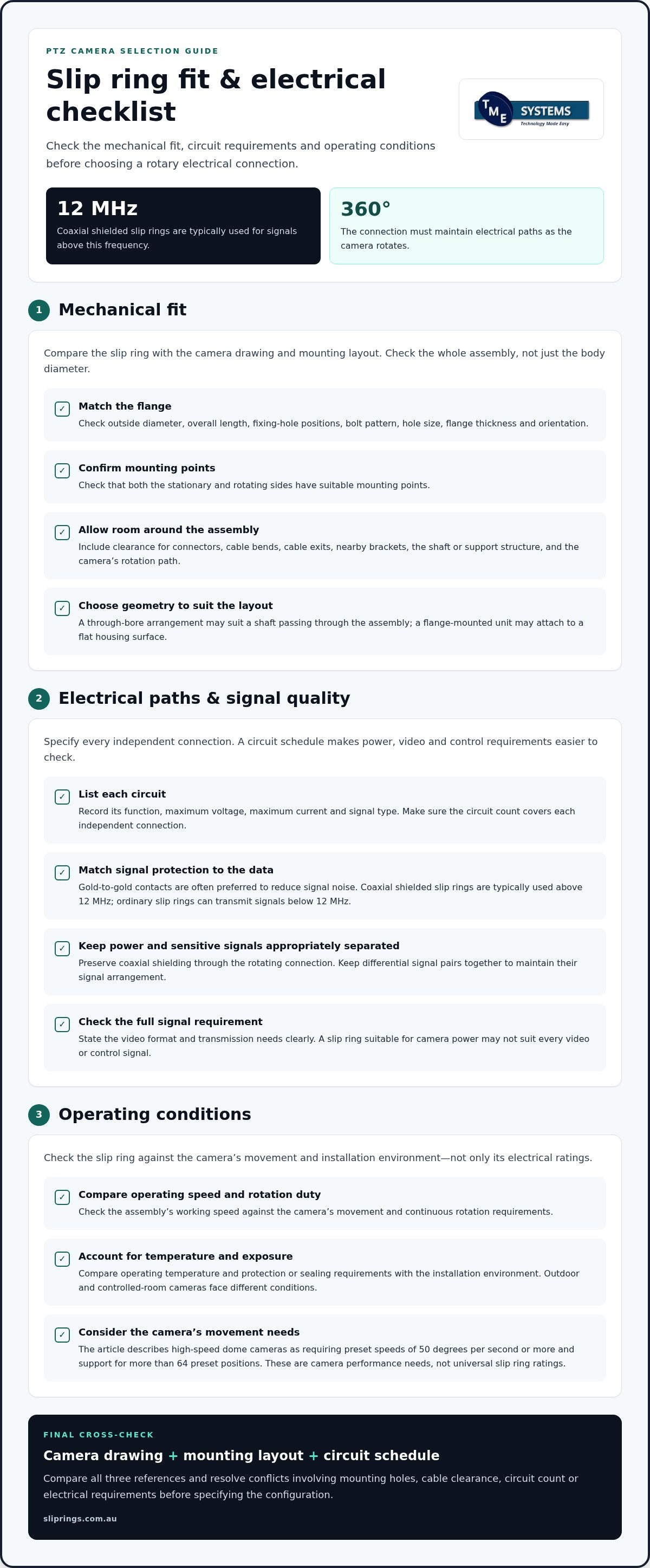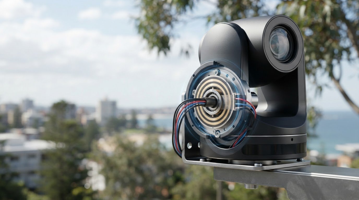
Signal quality can deteriorate when a PTZ camera sends high-resolution data through a rotating connection. For a slip ring for PTZ camera use, gold-to-gold contacts are often preferred to reduce noise during signal transmission, while coaxial shielded slip rings are typically used for signals above 12 MHz. The slip ring also needs to maintain electrical connections as the camera rotates through 360 degrees.
Interference matters, but contact material is only one part of selecting a slip ring for a PTZ camera. Fit, circuit count, maximum voltage and current, operating speed, temperature and environmental protection all influence which rotary electrical connection suits the camera. This guide explains what to assess in the dimensions and electrical ratings, and how materials and continuous rotation affect the choice. You’ll have a practical basis for matching the slip ring to the camera’s data, power and mounting requirements.
Key Takeaways
- Match signal protection to the data being transmitted; coaxial shielded slip rings are typically used for signals above 12 MHz.
- Assess the flange dimensions alongside circuit count and the maximum voltage and current required by the camera.
- Compare conductive ring and brush materials with the camera’s operating speed and duty requirements.
- Understand how the rotary connection carries power and signals between stationary and rotating camera parts during continuous 360-degree rotation.
- Use the camera’s mounting arrangement and operating conditions to narrow down a suitable slip ring configuration.
Do conductive slip rings have signal anti-interference measures?
Yes. A slip ring can help limit interference through its contact materials, shielding and circuit layout. Gold-to-gold contacts are often preferred in camera systems because they conduct well and can reduce signal noise. When choosing a slip ring for a PTZ camera, match its signal paths to the video format and transmission requirements, not just the power needs.
Conventional slip ring technology can cause signal deterioration with high-speed, high-resolution data, including HDTV and 4K2K video. Coaxial shielded slip rings are typically used above 12 MHz, while ordinary slip rings can transmit signals below 12 MHz. Keep power and sensitive signal circuits appropriately separated, and preserve coaxial shielding through the rotating connection to reduce unwanted electrical noise.
A capsule slip ring is a compact, solid unit for end-of-shaft mounting; a through-bore slip ring has a hollow centre for fitting over a shaft or routing auxiliary components. For a medium-speed ball camera, a capsule electric slip ring can support continuous 360-degree rotation. High-speed dome cameras can also use slip ring assemblies, with required operating speed and video signal quality guiding the selection.
High-speed dome camera movement can allow unlimited horizontal rotation through 360 degrees. The research describes these cameras as requiring preset speeds of 50 degrees per second or more and support for more than 64 preset positions. These figures describe camera performance needs, not a universal slip ring rating. Check the assembly’s working speed and signal-channel capacity against the camera’s movement and data requirements.
Rings carry the electrical paths, while brushes maintain contact as the assembly rotates. Cable connections link those paths to the stationary system and moving camera. A wiring map helps keep power, video and control conductors on their intended circuits. Differential channels carry balanced signal pairs, so keep each pair together to preserve its signal arrangement. Cylindrical describes an assembly’s shape, while differential describes its signal configuration.
Indoor, outdoor and high-speed applications call for different selection priorities. Compare the operating temperature and protection or sealing requirements with the installation environment. For high-speed use, assess operating speed and signal performance alongside circuit count. An outdoor camera needs protection suited to its exposure, while a fast dome also needs a slip ring compatible with its movement and video transmission.
Alternatives include a cable loop for cameras with limited rotation, or a wireless data link if the design also addresses power delivery. Neither provides the same combined rotating electrical connection as a slip ring. To install or replace one, isolate camera power, record the wiring connections, fit the assembly in its intended position, then reconnect and test power, video and control through the full rotation.
Intermittent video, noise, signal dropouts or inconsistent camera movement can indicate a contact, cable or connection problem. As part of maintenance, inspect connections and contact surfaces for wear or contamination. Service life depends on operating speed, rotation duty, environment and contact materials, so no single life figure applies to every camera.
Flanged slip ring dimensions and electrical rating
A flange must fit the camera’s mounting face and rotating assembly without restricting movement. Compare the available mounting area with the slip ring’s outside diameter, overall length and fixing-hole positions. For example, a unit may fit the camera housing but still block a cable exit or nearby bracket. A dimensioned drawing helps assess these clearances before selecting a configuration.
Assess the flange interface as a mechanical connection, not just by diameter. Confirm the bolt pattern, hole size, flange thickness and orientation against the camera assembly drawing. Both stationary and rotating sides need suitable mounting points. If the slip ring sits inside a dome, allow space for connectors and cable bends, not just the body itself.
Installation clearance matters both during operation and servicing. Identify the shaft or support structure, the camera’s rotation path and nearby wiring before finalising dimensions. A through-bore arrangement may suit a shaft passing through the assembly, while a flange-mounted unit may attach to a flat housing surface. The right geometry depends on the camera’s mechanical layout.
Start electrical selection with the maximum voltage and current required by each power and signal circuit. Compare those demands with the slip ring’s ratings rather than treating it as one undivided electrical path. For example, a camera may need separate paths for motor power, video and control. The circuit count must cover each independent connection.
Record the electrical requirements in a circuit schedule. For each circuit, include its function, maximum voltage and current, and signal type. This makes it easier to identify power circuits alongside sensitive data paths. Specify the signal format and transmission needs clearly, since an assembly suitable for camera power may not suit every video or control signal.
Check the complete operating conditions alongside the nameplate ratings. Operating speed, ambient temperature and protection or sealing requirements all affect selection. An outdoor camera faces different environmental conditions from one in a controlled room. Maximum voltage and current remain essential, while the environment and rotation duty also shape how the assembly performs.
Before specifying the flange, compare three references: the camera drawing, mounting layout and circuit schedule. Resolve any conflicts involving mounting holes, body clearance or cable routing before installation. This review helps prevent selecting a mechanically compatible unit with unsuitable electrical ratings. Treat dimensions and electrical requirements as one interface, not separate purchasing decisions.
Conductive ring and brush materials
Material pairing affects contact resistance, friction and wear in a PTZ camera slip ring. Assess the ring and brush as one interface, since a suitable material on one side alone does not establish compatibility.
Conductive ring materials
A conductive ring is the contact surface carried by the rotating assembly. Ring substrates and surface finishes are selected for electrical performance and wear resistance. In a PTZ camera, the contact surface must suit the duty of its assigned circuit. Material choice can affect how consistently that circuit performs during operation.
Compare the ring surface with the brush material rather than assessing either in isolation. A mismatch can change friction and contact resistance, affecting wear at the interface. For example, a camera in a dusty plant room has different surface-protection considerations from one in a clean indoor enclosure. Let the working environment inform the material pairing.
Surface condition matters too. A finish suited to the electrical path may still need protection from contamination or corrosion in the installation environment. Consider whether the camera housing limits exposure and whether the ring can be inspected during scheduled maintenance. These details help determine which ring material and surface treatment suit the application.
Brush materials
A brush is the element that contacts the ring surface; its composition influences friction, electrical contact and wear. In a PTZ camera, these properties matter because movement repeatedly brings the materials into sliding contact. Choose materials with the circuit’s function and camera’s operating pattern in mind, not just the name of the brush material.
Brush options include precious-metal contact elements and carbon-based contacts. Each design interacts differently with the ring surface, so assess the pair together. For example, a compact camera assembly with limited inspection access may need a contact design suited to its maintenance access and operating duty.
Material selection also affects how you interpret inspection findings. A change in surface appearance may be normal for one contact design but indicate damage in another. Record the selected ring and brush materials in the assembly documentation, then compare inspection observations with that design. This gives maintenance teams a consistent reference for assessing contact condition.
For a camera exposed to temperature changes or airborne contaminants, consider how the environment affects both contact materials. The combination should suit the housing, circuit function and rotation duty as a complete interface. Choosing a material based only on conductivity can overlook the mechanical contact behaviour that influences long-term operation.
Multifiber brushes can offer enhanced durability and efficiency in slip rings used at high rotational speeds or in heavy-duty applications, making operating conditions an important factor in material pairing.
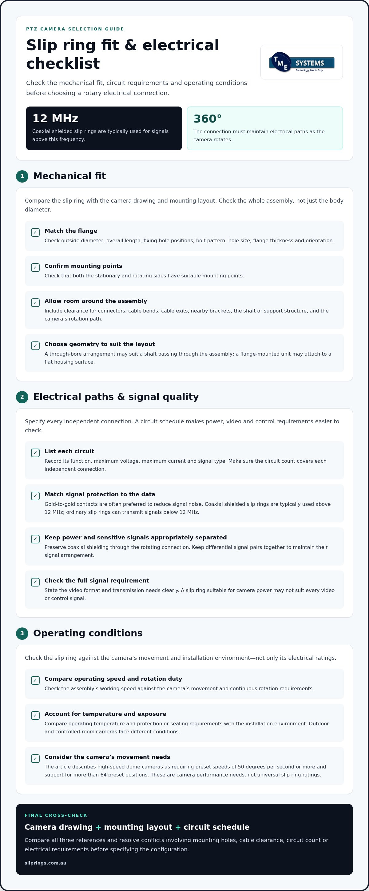
Continuous 360-degree rotation while maintaining electrical connections
Continuous camera movement places mechanical and electrical demands on the rotating interface. Assess the movement pattern alongside the camera’s mounting arrangement and operating conditions.
Slip ring operation
In a PTZ assembly, the slip ring transfers electrical services across the camera’s moving interface throughout its operating cycle. This matters when a camera must remain connected while its viewing direction changes. Consider whether movement is occasional, repeated or sustained, as each pattern creates a different operating duty for the assembly.
Consider the full motion profile, not just the camera’s maximum movement. A surveillance camera may pause at preset views, then reposition frequently between them. Another installation may track moving activity for extended periods. These use cases place different demands on the rotating interface, even when the cameras share a housing and mounting arrangement.
Direction changes are also part of the application description. A camera that repeatedly reverses direction has a different movement pattern from one that turns mainly in one direction. Describe how the camera operates during normal surveillance, including preset movement and manual control, so the interface suits the actual duty.
Rotation with electrical connections
Maintaining electrical continuity during camera movement depends on matching the rotary interface to the circuits and motion profile. The design must carry the camera’s required services while the viewing head moves, not only when it is stationary. For example, a moving camera may need video and control signals throughout a repositioning sequence.
Test the complete camera system through its intended movements while monitoring the live image, control response and power behaviour. If a fault appears only during movement, record the direction and point in the camera cycle where it occurs. This helps distinguish movement-related issues from faults present at rest.
Mechanical integration can affect operation too. Check that the assembly fits the support structure and that connected cables do not interfere with the moving camera or surrounding enclosure. For example, a compact dome housing may leave less room for cable routing than a larger camera body. The mounting layout must accommodate the interface without obstructing movement.
Environmental conditions are another selection factor. An outdoor camera may face dust, moisture and temperature variation, while an indoor unit may operate in a cleaner, more controlled space. Match protection and sealing requirements to the installation, then assess the camera’s duty and signal needs together. This aligns mechanical operation with electrical requirements during normal use.
Document the movement pattern, mounting constraints and electrical services in the camera specification. A clear application description helps engineers assess the rotary interface against the complete installation, including the camera’s operating cycle and environment.
What is a slip ring in a PTZ camera and how does it work?
In a PTZ camera system, the slip ring provides the electrical hand-off between fixed equipment and the moving camera assembly. It carries assigned services across that boundary; it does not decode video, issue movement commands or replace the camera controller. Understanding this distinction helps place the connector correctly within the system.
Map the signal route across the connected system components. A control device sends movement commands to the camera, which returns video to recording or monitoring equipment. Power also feeds the camera and its movement functions. The rotary interface sits within these routes, so its circuit arrangement must match the connections designed into the camera and surrounding equipment.
Identify each service and its electrical path. A wiring diagram should show where stationary-side conductors enter the assembly and where rotating-side conductors continue to camera components. For example, label camera power, network data and pan-and-tilt control separately. This record helps prevent a signal or supply from being assigned to the wrong terminal during assembly.
Signal type matters at the system boundary. Ethernet, analogue video and control signals have different transmission requirements, so do not assume a connector selected for one service suits another. Identify the camera interface and the connected equipment at the other end. This clarifies what the rotary connection must carry without confusing connector capability with camera functionality.
The interface location affects the wiring architecture. Account for the transition from stationary cabling to conductors within the moving camera assembly. Cable termination, connector access and routing space all influence integration. A drawing of both the camera and its supporting structure can reveal conflicts that a component-only layout misses.
During commissioning, verify the complete chain from controller to camera and from camera to monitor or recorder. Confirm that commands reach the camera and the expected image returns through the system. If a service fails, tracing its documented route helps distinguish a rotary-interface issue from a camera, controller or network fault.
Treat the slip ring as a defined connection point within a larger electrical design. Clear circuit identification, compatible signal paths and a system-level wiring record make its role easier to specify and maintain. This approach treats the camera, controller and recording equipment as connected parts while preserving their distinct functions.
The interface consists of two rings of different sizes. This physical description complements its role as an electrical hand-off. The key design question is which assigned services cross between fixed equipment and the moving camera assembly, and whether each path matches the camera’s connections and surrounding equipment.
TME Systems: Mercotac Slip Rings
TME Systems Pty Ltd can help match a PTZ camera’s circuit, signal, mounting and rotation requirements with a suitable slip ring. Turn to its technical application consulting when selecting a rotary electrical connector for a new camera design or reviewing an existing configuration.
Its range includes Mercotac Slip Rings, alongside Meridian Laboratory, BGB Innovation and Prosper Rotation Slip Rings. A useful starting point is a clear specification covering circuit count, maximum voltage and current, working speed, mounting arrangement and environmental conditions. These details help focus the selection on the camera’s actual operating requirements, rather than on a form factor alone.
For help matching a slip ring to your PTZ camera application, contact TME Systems Pty Ltd.
Turn your camera requirements into a clear specification
Before procurement, record the camera interface requirements in one place. A concise specification connects the mechanical layout with the electrical design, giving engineering and purchasing teams a shared reference. Include the mounting drawing, circuit schedule, signal format and operating conditions. This record can also support future replacement decisions if the camera or its wiring changes.
For a slip ring for a PTZ camera, align the requirements with the application rather than selecting by form factor alone. TME Systems’ technical application consulting can help assess the design requirements and relevant product options, including Mercotac Slip Rings, Meridian Laboratory Slip Rings and BGB Innovation Slip Rings.
Bring your camera drawings and electrical requirements together, then contact TME Systems for slip ring advice. A well-defined specification gives your team a practical starting point for the next design decision.
Frequently Asked Questions
Which slip ring specifications are needed for a PTZ camera?
A slip ring for a PTZ camera needs a specification that covers its electrical interface, data paths and installation conditions. Start with the camera wiring diagram and identify every connection, including Ethernet or video format, control wiring and motor supply. Add the mounting envelope, operating speed, ambient temperature and sealing requirements. Record cable-entry direction and termination style too, as both affect fit inside the camera housing and the wiring layout.
How many circuits and what current and voltage ratings does a PTZ camera slip ring need?
There is no universal circuit count or current and voltage rating for PTZ cameras. Count each independent path in the camera wiring diagram, then document the maximum voltage and current for every power circuit. Include simultaneous loads, such as camera electronics and movement motors, as specified by the camera design. Signal channels need compatible transmission characteristics, so do not treat every path as interchangeable or infer ratings from the camera’s overall supply alone.
Can a slip ring transmit Ethernet, PoE, video, and control signals reliably?
Yes, suitable slip rings can carry Ethernet, power, video and control, but capability depends on the model and application. TME Systems’ product information lists Ethernet, fieldbus, analogue, control and fibre-optic signal options across applicable models. For PoE, assess the combined data and power requirements as one interface, then match the connector arrangement and transmission needs to the camera network. Suitability depends on the model’s documented performance for those signals.