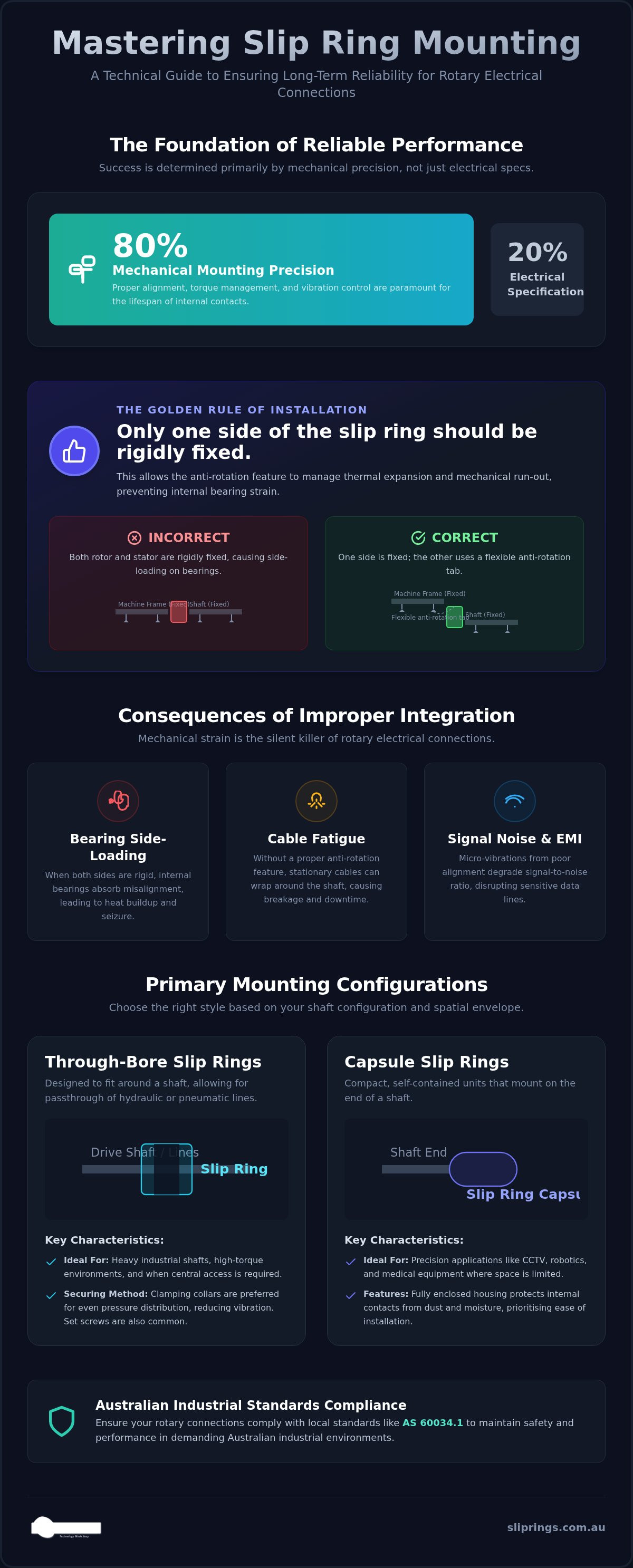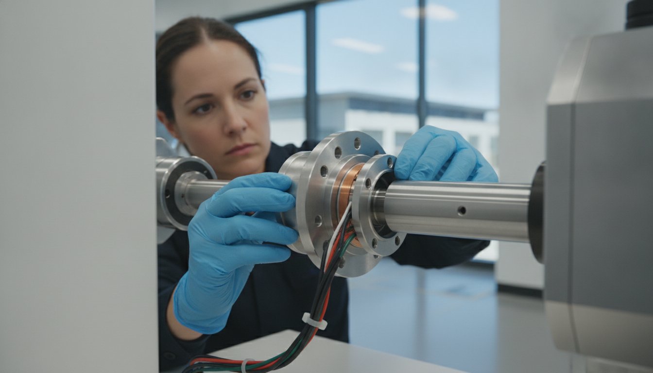
Reliable slip ring performance is 20% electrical specification and 80% mechanical mounting precision. While it is natural to focus on circuit counts and current ratings, even the most advanced hardware will fail prematurely if it is strangled by a rigid mounting bracket or misaligned shaft. You likely recognise the frustration of dealing with signal noise or cable breakage that stems not from an electrical fault, but from basic mechanical strain within a tight spatial envelope.
Mastering the various slip ring mounting options is essential to protecting your equipment from vibration and improper torque management. This technical guide provides a pathway to selecting the correct configuration, whether your project requires a through-bore, flange, or capsule style. We will examine how to implement anti-rotation features correctly and ensure your installation meets Australian industrial safety standards, including AS 60034.1. By the end of this article, you will have the practical knowledge to secure your rotary electrical connections for long-term reliability and avoid the pitfalls of unsupported imports that lack local technical backing.
Key Takeaways
- Understand why mechanical mounting precision is the primary factor in determining the operational lifespan of internal precious metal or liquid metal contacts.
- Evaluate the technical trade-offs between through-bore, capsule, and flange slip ring mounting options to suit your specific spatial envelopes and drive shaft configurations.
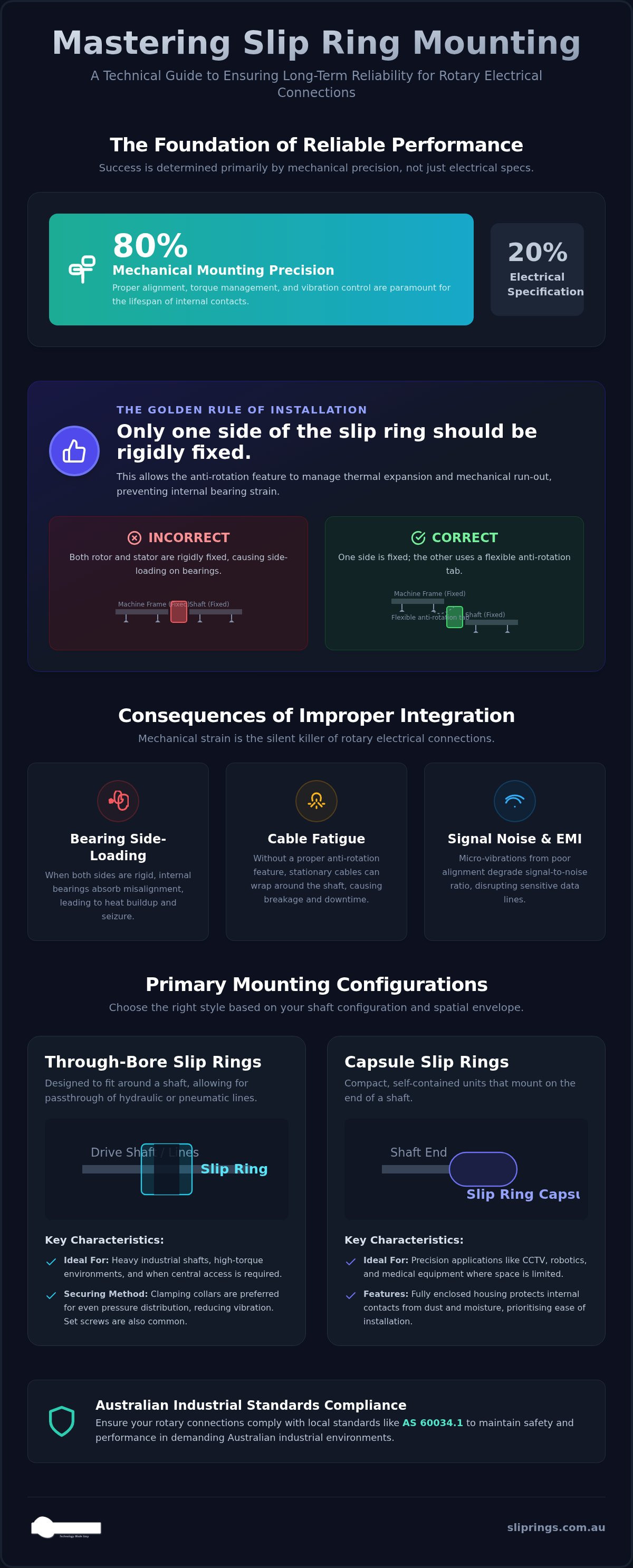
- Implement the "Golden Rule" of installation by ensuring only one side of the slip ring is rigidly fixed, allowing the anti-rotation feature to manage thermal expansion and mechanical run-out.
- Learn to match specific hardware brands, such as Mercotac or BGB Innovation, to your project's unique RPM, torque, and environmental exposure requirements.
- Ensure your rotary connections comply with Australian industrial standards, such as AS 60034.1, to maintain safety and performance in local industrial environments.
Understanding the Impact of Proper Slip Ring Mounting
A slip ring serves as the essential mechanical bridge between stationary and rotating structures. While its primary function is electrical, its performance is almost entirely dependent on mechanical integrity. The choice of slip ring mounting options isn't just about fitting the unit into a spatial envelope; it's about defining how the internal components interact under load. When a unit is correctly integrated, the internal precious metal or liquid metal contacts maintain a stable, low-resistance path. If the mounting is imprecise, the resulting mechanical run-out creates micro-vibrations that manifest as electrical noise or electromagnetic interference (EMI), particularly in sensitive data lines.
In heavy industrial plants, mounting choices also dictate maintenance accessibility. A poorly positioned unit in a mining conveyor or a packaging line can turn a simple inspection into a multi-hour teardown. Proper integration ensures that the slip ring is protected from the primary drive's mechanical stresses while remaining accessible for routine checks. This balance is critical for ensuring the 24/7 operational reliability required in Australian industrial environments.
The Consequences of Improper Integration
Bearing side-loading is the most frequent cause of premature failure in rotary connectors. When both the rotating and stationary sides are rigidly fixed without allowing for misalignment, the internal bearings are forced to absorb the machine's structural tolerances. This "silent killer" leads to heat buildup and eventual seizure. Beyond the unit itself, improper torque management often results in cable fatigue. Without a dedicated anti-rotation feature, the stationary cables may eventually "wrap around" the rotating shaft, leading to catastrophic breakage and immediate system downtime. Furthermore, excessive vibration from poor alignment degrades the signal-to-noise ratio, which is devastating for high-speed fieldbus protocols used in modern automation.
Rotor vs Stator: Identifying Your Drive System
To select the right hardware, you must first standardise your terminology. The "rotor" is the component that rotates with the machinery shaft, while the "stator" remains stationary to facilitate cable entry. Identifying which component must stay fixed is usually determined by your existing cable architecture. In Australian packaging machinery, high-speed rotation often requires Mercotac Slip Rings where the rotor is typically the smaller, inner component. Conversely, in heavy mining equipment, the stator might be a large external housing. Always ensure the side with the most complex or fragile cabling is the one designated as the stator to minimise mechanical strain during operation.
Primary Mechanical Mounting Configurations: Through-Bore vs Capsule
Selecting the right slip ring mounting options begins with a fundamental decision: does the unit need to sit around the shaft or at the end of it? This choice determines the mechanical stability of the entire rotary union. Through-bore configurations are often used when the centre of rotation is occupied by a drive shaft, hydraulic lines, or pneumatic piping. Capsule designs are self-contained units that prioritise compact dimensions and ease of installation in smaller machinery where the shaft end is accessible.
Through-Bore Integration for Heavy Shafts
Through-bore integration requires a precise match between the unit's internal diameter (ID) and the shaft's outer diameter. For heavy industrial shafts, securing the rotor is typically achieved via set screws, friction fits, or clamping collars. Clamping collars are generally preferred because they distribute pressure more evenly across the shaft, which reduces the risk of vibration-induced loosening. This method is essential in high-torque environments where even minor mechanical run-out can lead to signal degradation. For a technical perspective on how these mechanical interfaces are engineered for demanding environments, this Slip ring assembly patent provides an excellent example of high-performance mounting hardware.
Capsule Designs for Precision and Space
Capsule designs are the preferred choice for precision-led applications like CCTV systems, medical equipment, and robotics. These units feature fully enclosed housings that protect the internal contacts from dust and debris. Many versatile configurations, such as those found in Prosper Rotation slip rings, utilise gold-on-gold contact technology to maintain signal integrity in very small mounting envelopes. Because these are end-of-shaft solutions, they don't require the same radial clearance as hollow-shaft models, making them the standard for tight spatial constraints.
There is a distinct trade-off between these two styles regarding RPM ratings and circuit density. Through-bore units can often handle higher rotational speeds because the mechanical load is distributed over a larger bearing surface. However, capsules typically offer higher circuit density for their overall volume. In height-restricted applications, engineers often compare through-bore units with "pancake" styles. While pancake rings are flatter, they often exhibit higher brush wear and increased crosstalk compared to the more robust through-bore design. If you're struggling to fit a standard unit into your machine's footprint, consulting with a technical specialist can help you identify a more efficient configuration.
Flange Mounting Options and Orientation
Flange mounting offers a stable mechanical interface for applications requiring precise alignment and structural support. Unlike simple shaft-mounted units, a flange provides a flat, load-bearing surface that simplifies integration into machine housings. You've likely found that the choice between a rotor flange and a stator flange depends entirely on where your primary structural support is available. A rotor flange is fixed to the rotating component, while a stator flange secures the housing to a stationary bulkhead. This distinction is vital for maintaining the concentricity of the unit, as discussed in this NASA report on electrical slip rings, which highlights the critical role of mechanical integration in high-reliability environments.
Flanges are also instrumental in achieving high Ingress Protection (IP) ratings. The flat mounting surface allows for the use of gaskets or O-rings to seal the interface against moisture and dust. Standard slip ring mounting options often include common bolt patterns, but Australian machinery retrofits frequently require customisation to match existing mounting holes in legacy hardware. Ensuring a flush fit between the flange and the mounting surface is the first step in preventing environmental ingress and mechanical vibration.
Vertical vs Horizontal Flange Alignment
Orientation is a non-negotiable factor when selecting your hardware. In vertical applications, gravity can influence the internal distribution of lubricants or conductive media. For instance, Mercotac slip rings utilise liquid metal technology that requires specific mounting orientations to prevent lubricant migration. You must ensure the flange face is perfectly perpendicular to the axis of rotation. Any angular misalignment creates a "wobble" that increases mechanical wear on the internal brushes and leads to premature bearing failure. It's essential to audit your machine's alignment before finalising the installation.
Pancake Slip Rings: The Low-Profile Alternative
When vertical height is severely restricted, a pancake slip ring is often the only viable solution. While through-bore or capsule models are elongated, pancake designs arrange the circuits in concentric tracks on a flat plane. This low-profile alternative presents unique mechanical challenges that aren't found in other slip ring mounting options. Managing concentricity is more difficult because the brushes move across a wider surface area. Unlike a through-bore unit that naturally centres on a shaft, pancake designs require specialised mounting plates to maintain stability. If you're choosing between a pancake and a through-bore unit, consider that the latter usually offers better longevity due to its superior mechanical balance. Pancake designs should only be used when spatial envelopes leave no other choice.
The Critical Role of Anti-Rotation Features and Alignment
The "Golden Rule" of mechanical integration is simple: never rigidly fix both the rotor and the stator. While it's tempting to bolt every component tightly to the machine frame to prevent vibration, this approach is the leading cause of premature bearing failure. A slip ring is a precision instrument, not a structural support. When both sides are locked down, the unit is forced to compensate for the machine's inherent thermal expansion and mechanical run-out. This creates massive internal stresses that "strangle" the bearings and lead to rapid contact wear. Effective slip ring mounting options must always incorporate a degree of "float" to allow the unit to self-align during rotation.
An anti-rotation tab, often called a torque arm, is the primary mechanism used to achieve this float. It prevents the stationary housing from spinning while allowing it to move slightly in response to shaft eccentricity. This movement prevents the slip ring from becoming a load-bearing component of the drive train, ensuring the internal contacts remain perfectly aligned even if the drive shaft isn't perfectly true.
Implementing a Floating Stator Mount
Achieving a reliable installation requires a methodical approach to ensure no axial or radial loads are transmitted to the housing. Follow these four steps to organise a standard floating mount:
- Step 1: Secure the rotor firmly to the rotating shaft using the manufacturer's recommended set screws or clamping collars.
- Step 2: Attach the stationary wires with enough slack to allow for minor movement. Rigid cabling can act as a lever, pulling the stator out of alignment.
- Step 3: Engage the anti-rotation tab with a loose-fitting pin or bracket. There should be a visible gap (typically 1-2mm) to allow for thermal expansion.
- Step 4: Verify the installation by rotating the shaft manually. The slip ring housing should "breathe" slightly rather than fighting against its mount.
Managing Shaft Run-out and Vibration
Most industrial slip rings can tolerate a shaft run-out of approximately 0.05mm to 0.1mm, but exceeding these limits will introduce significant electrical interference. In high-vibration Australian mining environments, standard mounting brackets often require the addition of flexible couplings or rubber dampeners to isolate the unit from structural shock. Failure to manage these mechanical forces often leads to the issues detailed in our guide on Troubleshooting Signal Noise in Rotary Connections. If your application involves high-frequency vibration, selecting a robust BGB Innovation unit designed for heavy industry is the most pragmatic way to ensure long-term stability.
To ensure your specific configuration provides enough clearance for mechanical run-out, you can request a technical consultation with our engineering team.
Selecting the Right Mounting Style for Your Application
Developing a robust framework for slip ring mounting options requires a holistic view of your machine's operating parameters. You must weigh rotational speed against the required circuit density and the physical constraints of the existing drive train. Selecting a mounting style isn't merely a matter of spatial fit; it is about ensuring the mechanical interface can withstand the torque and environmental exposure of your specific site. For high-speed precision applications, brands like Mercotac offer liquid metal interfaces that require strict orientation. Conversely, for the rugged demands of heavy industry, BGB Innovation provides robust housings that prioritise durability over miniaturisation.
Mounting Selection Framework
To identify the most pragmatic solution for your project, use the following decision matrix based on your primary mechanical requirements:
- Through-Bore: Select this if the centre of rotation must accommodate a drive shaft, pneumatic lines, or hydraulic piping. It provides excellent mechanical stability for large-diameter shafts.
- Pancake: Use this style only when vertical height is extremely limited and a standard cylindrical unit cannot fit. Be prepared to manage the increased brush wear associated with flat-disc designs.
- End-of-Shaft: If high-speed signal integrity is your primary goal, Meridian Laboratory end-of-shaft mounts are the industry standard. These units are engineered to minimise electrical noise at high RPMs.
Procurement and Technical Support in Australia
Consulting with an application engineer before finalising your design is the most effective way to avoid the "solar cowboy" equivalent of the slip ring industry. Unsupported imports often lack the precise tolerances required for long-term reliability in Australian conditions. TME Systems, based in New South Wales, provides specialised technical application consulting to bridge the gap between complex manufacturing capabilities and your specific engineering needs. This local expertise ensures that you select a mounting configuration that complies with AS 60034.1 and other relevant performance standards.
To assist with your mechanical integration, we provide access to 3D CAD models that can be dropped directly into your designs. This reduces lead times and eliminates the guesswork often associated with custom retrofits. For more detailed advice on selecting a partner for your next project, refer to our guide on Industrial Slip Ring Supplier Australia: A Professional Procurement Guide. Our team is focused on ensuring the technical success of your project through precise hardware selection and dependable local support.
Optimising Mechanical Integration for Rotary Reliability
Achieving long-term success with rotary electrical connections depends on a precise balance between electrical specification and mechanical precision. By implementing the "Golden Rule" of floating stator mounts, you protect internal bearings from the destructive forces of rigid fixing and thermal expansion. Whether your project requires the high-speed integrity of a through-bore unit or the compact footprint of a capsule design, selecting the correct slip ring mounting options is the most pragmatic way to ensure system uptime.
As an authorised Australian distributor for Mercotac and Meridian Laboratory, TME Systems provides the specialised technical consulting needed to navigate complex rotary integrations. We offer a comprehensive range of mounting styles to suit any industrial application, from heavy mining machinery to precision robotics. Don't leave your machine's reliability to chance by using unsupported imports that lack local engineering support. Contact TME Systems for expert technical advice on your slip ring mounting requirements. We look forward to helping you secure a robust and efficient solution for your next engineering challenge.
Frequently Asked Questions
Can I mount a slip ring in any orientation (horizontal or vertical)?
Most industrial slip rings support both horizontal and vertical mounting, provided the mechanical alignment is precise. However, orientation is critical for liquid metal connectors like Mercotac units, which often require a vertical or specific angular position to prevent internal fluid migration. Always verify the manufacturer's specification before installation, as improper orientation in these specialised units leads to immediate internal shorting and permanent hardware damage. Standard brush-based units are generally more flexible regarding orientation.
What is an anti-rotation tab and why is it necessary for mounting?
An anti-rotation tab is a mechanical feature that prevents the stationary housing from rotating with the shaft while allowing for minor radial and axial movement. This "float" is essential because it accommodates shaft run-out and thermal expansion. Without this feature, the housing would rotate, causing the stationary cables to wrap around the drive shaft. This leads to catastrophic cable failure and potential damage to the machine's internal electrical interfaces and structural integrity.
How do I choose between a through-bore and a capsule slip ring for my machine?
Base your decision on the physical location of the rotating shaft. Select a through-bore model if you need to pass a drive shaft, hydraulic lines, or pneumatic piping through the centre of the unit. These are ideal for high-torque industrial machinery. Conversely, a capsule slip ring is a self-contained unit best suited for end-of-shaft applications where space is limited, such as in robotics or surveillance systems that require high circuit density in a small envelope.
Do I need a specialised bracket for mounting a Mercotac liquid metal connector?
Mercotac units require precise mounting to avoid side-loading the internal bearings. While a custom bracket isn't always mandatory, the mounting interface must ensure the unit is not rigidly fixed on both sides. Using a floating torque arm or a flexible coupling is highly recommended to protect the liquid metal contacts from vibration. TME Systems provides technical consulting to help you design a bracketry system that maintains the required orientation and ensures mechanical isolation.
What happens if I rigidly bolt both sides of the slip ring to the machine?
Rigidly bolting both the rotor and stator is the primary cause of premature bearing failure. This configuration forces the slip ring's internal bearings to absorb the machine's structural tolerances and thermal expansion. The resulting side-loading creates excessive heat and mechanical friction, which eventually seizes the unit. To maintain long-term reliability, always ensure one side remains "floating" by using an anti-rotation tab or a loose-fitting pin rather than a rigid bolt or clamp.
How does mounting affect the IP rating and environmental sealing of the connector?
The choice of slip ring mounting options directly impacts the unit's ability to resist moisture and dust. Flange mounting is the most effective way to maintain a high IP rating, as it allows for the use of gaskets or O-rings against a flat, stable surface. Improper mounting that causes shaft run-out or vibration can compromise internal seals over time, allowing contaminants to enter the housing. This leads to increased electrical noise and eventual contact corrosion in harsh environments.
Can a slip ring be used as a bearing to support a rotating load?
A slip ring must never be used as a primary bearing to support a rotating load. These units are precision electrical components designed to transmit signals, not to withstand radial or axial mechanical forces. Subjecting a slip ring to structural loads will lead to immediate bearing deformation and internal contact misalignment. You must ensure the rotating shaft is fully supported by its own independent bearing system before integrating the rotary electrical connector into the drive train.
What are the mounting requirements for high-speed applications exceeding 1000 RPM?
High-speed applications require exceptional mechanical balance and precision alignment to prevent centrifugal forces from damaging the contacts. At speeds exceeding 1000 RPM, even minor eccentricity becomes a major source of vibration and electrical noise. You should use balanced rotors and ensure the mounting bracketry is extremely rigid yet allows for the necessary stator float. For these requirements, Meridian Laboratory units are often preferred due to their superior high-speed mechanical stability and low-resistance contact technology.