A larger switchboard is not automatically a better expansion plan. Specifying the number of circuits for future expansion means allowing for credible future loads, not treating every spare way as a required circuit.
Planning ahead matters because adding equipment can affect more than the space available on a switchboard. Circuit count must also reflect what each circuit will supply, its electrical requirements and protection, and how the installation will operate.
This article explains how to estimate future circuit demand, distinguish spare physical space from installed circuit capacity, and assess the drawbacks of over-specifying a switchboard. It also explains when an existing arrangement may accommodate an additional circuit and when a new circuit or broader redesign is more suitable. The aim is to support expansion while keeping the design aligned with the installation’s actual requirements.
Key Takeaways
- Base circuit capacity on the equipment and operating scenarios the switchboard must support, including planned expansion.
- Distinguish between reserving physical space for future circuits and installing spare circuits now; each addresses a different need.
- Assess whether an existing circuit can accommodate an added load or whether a separate circuit is needed, considering capacity and protection.
- Too few circuits can constrain future equipment choices and make later changes to the installation more involved.
- Plan circuit types and protection around the loads they serve, with AS/NZS 3000:2018 as the Australian Wiring Rules reference.
Deciding between circuit expansion and a new circuit
For a slip ring, expansion means adding electrical paths to an existing rotary electrical joint or selecting a unit with more capacity. The right choice depends on the devices, voltage, current and signals the installation must supply.
Installing spare circuits or reserving board space
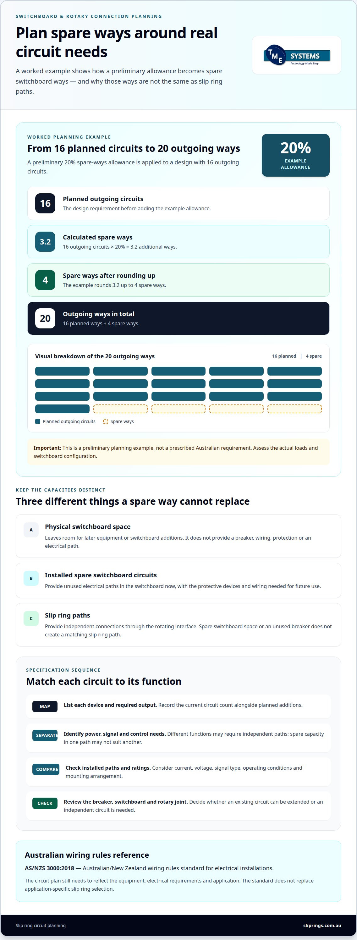
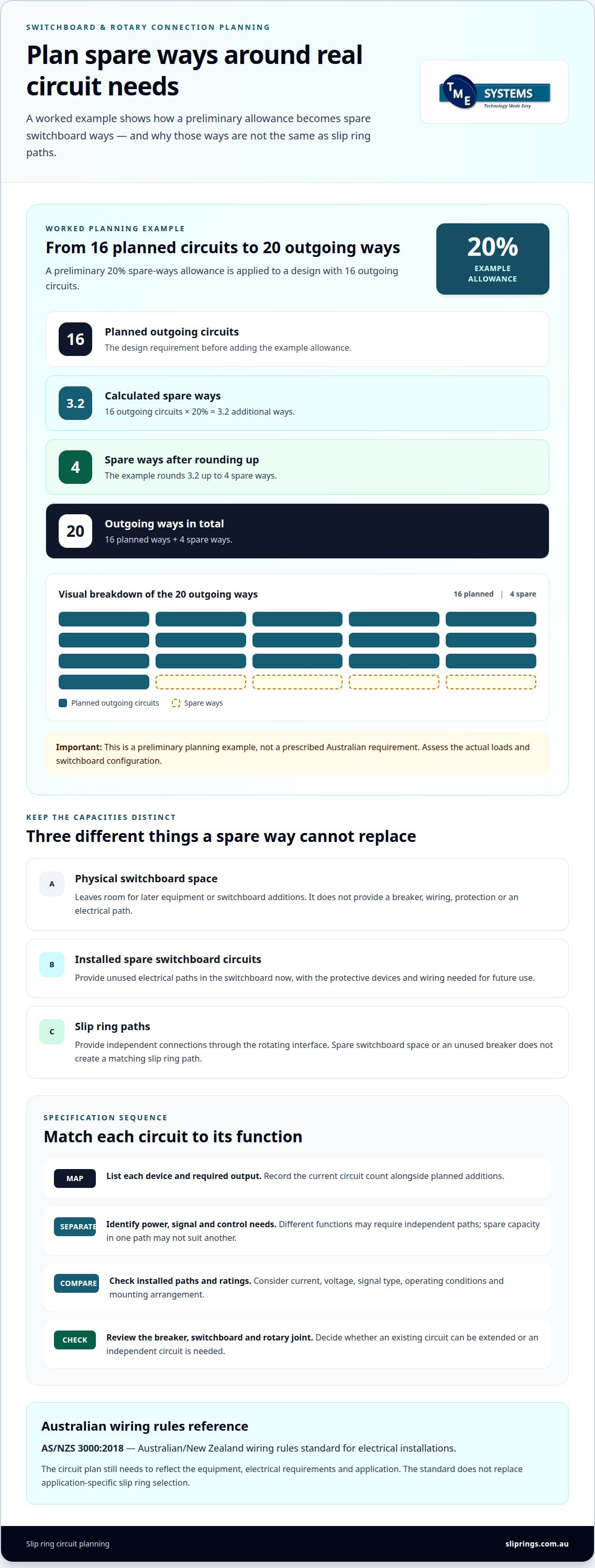
Installing spare circuits provides unused electrical paths now; reserving board space leaves room for later switchboard additions. These solve different problems: spare slip ring paths support future connections through the rotating interface, while a vacant switchboard section provides physical room only. Space beside a breaker, for example, does not create another slip ring outlet or path.
Map each planned device to its connection, then distinguish the slip ring circuit count from the switchboard’s outgoing circuits. A future lighting load might need a new switchboard circuit, while a rotating assembly may need another independent path through its rotary joint. The installation needs both only if its supply arrangement requires them.
Expanding an existing slip ring configuration is appropriate when its current paths and electrical ratings can serve the added devices without compromising existing outputs. Review current and future loads, voltage, signal type, operating conditions and mounting arrangement together. A power path and a signal path serve different functions, so spare capacity in one does not automatically meet the other’s requirements.
A new circuit is the clearer option when added equipment needs an independent supply, control signal or isolation from existing devices. For example, combining a new control signal with a power path may not suit the required operation. Identify each electrical function as a separate design requirement before deciding whether an existing circuit can be extended.
Risks of undersupplying circuits
Underspecifying circuits means providing fewer independent paths than the installation’s planned devices and functions require. During a renovation or new build, this can constrain later equipment choices, require changes to the switchboard configuration or leave a rotating connection unable to serve an added device. A spare physical way alone cannot provide the missing path.
For instance, a machine may need separate paths for power and control signals, with another device added later. If the original circuit count covered only the first configuration, the added function may require a new rotary electrical joint or a redesign. Match the circuit count to the actual functions, not just the number of devices.
Use a simple decision sequence: identify each device and required output; separate power, signal and control functions; then compare those needs with the installed paths and ratings. Check whether the breaker and switchboard can supply the proposed arrangement, and whether the rotary joint’s configuration supports it. In Australia, AS/NZS 3000:2018 is the wiring rules standard for electrical installations, but it does not replace application-specific slip ring selection.
For the specification, record the current circuit count alongside planned additions and their electrical requirements. This makes the distinction between adding a circuit and expanding an existing one explicit. It also prevents unused switchboard space from being mistaken for electrical capacity already in place.
Should spare circuits be installed now or only leave space in the switchboard?
Leaving space means reserving physical room in the switchboard for later equipment. Installing spare circuits means fitting the protective devices and wiring needed for future use. Choose based on whether the project needs room for later components or ready electrical paths. For rotating machinery, spare switchboard space does not create additional paths through the slip ring.
A preliminary distribution-board example uses a 20% spare-ways allowance. If the design needs 16 outgoing circuits, that allowance gives 3.2 additional ways. Rounding up produces 4 spare ways and 20 outgoing ways in total. This illustrates how an allowance can inform early planning; it is not a prescribed Australian requirement or a substitute for assessing the actual loads and board configuration.
Reserving space can suit projects where future equipment is still being defined. A plant extension, for example, may have a designated area for new equipment while its final loads and connection requirements remain undecided. Available space can give a later design room for suitable components. It does not determine the breaker rating, wiring, protection or rotary electrical paths the selected equipment will require.
Installing spare circuits now is more relevant when future equipment and its electrical requirements are clear. A planned control device, for instance, may need a dedicated path through a rotating interface and a suitable switchboard connection. Specify those paths by function, current, voltage and signal requirements. An unused breaker does not mean the slip ring has a matching spare circuit.
To choose between the options, separate the capacity questions. Identify present outgoing circuits and planned equipment. Determine whether future equipment needs additional switchboard circuits, slip ring paths, or both. Then assess board space, protective devices and installation configuration. In Australia, AS/NZS 3000:2018 is the Wiring Rules reference for electrical installations. The circuit plan still needs to reflect the equipment and application.
Use a documented allowance rather than adding spare ways without a design basis. The 20% example shows how a preliminary allowance can be translated into whole outgoing ways. Revisit the plan when the equipment schedule changes. If planned devices need independent power or signal paths, include those requirements in the rotary interface specification as well as the switchboard plan. This keeps future provision tied to the defined installation, rather than treating spare board space as electrical capacity.
One planning recommendation is to reserve 20% of electrical panel spaces for future expansion, with a minimum reserve of 6 modules in collective housing. Treat this as a space allowance: it can preserve room for later equipment, but it does not by itself provide a wired circuit or establish that a later load can be connected.
Record any allowance separately from circuits intended for immediate installation. Check that reserved space is accessible and suitable for eventual equipment, then revisit the arrangement as requirements become clearer. If future needs are unknown, the reserve provides flexibility, but it does not mean capacity, protection, wiring or slip ring paths are already available. Where requirements are known, specify the necessary circuit components rather than relying on empty panel space.
What are the risks of adding too few circuits?
Too few circuits can leave planned equipment without an appropriate independent electrical path. In a switchboard, this can constrain load distribution; in a slip ring, it can limit the separate power and signal paths across a rotating joint. These are related design questions, but switchboard circuit count and slip ring circuit count are not interchangeable.
A commercial-area example requires 16 outgoing circuits: 4 for lighting, 6 for socket outlets, 3 for air conditioning, 2 for exhaust fans and 1 for a water heater. If equipment is added beyond that schedule, the design needs to account for its supply and protection. Simply assigning new devices to existing circuits may not suit their use or electrical requirements.
Each circuit type has a specified wire cross-section, breaker rating and maximum number of points of use. Adding outlets or devices can therefore affect more than circuit count. A new appliance or specialised setup—such as commercial monitoring equipment from CCTVSecurityPros - Professional Security Cameras and Systems—may need a dedicated circuit, while extra lighting points serve a different function. The design must account for the equipment and required power, rather than treating every available connection as equivalent.
Rotating machinery adds another constraint. A slip ring’s circuit count describes its independent electrical paths for power and signal transmission. A machine with a power feed, control signals and feedback devices may need distinct paths for those functions. If the original selection provides too few, a later control-system change could require a different circuit configuration or rotary electrical joint.
Protection also needs to match the final-subcircuit design. In commercial and industrial environments, RCD protection is mandatory for final subcircuits up to 32 A. AS/NZS 3000:2018 is the Wiring Rules reference for assessing RCD requirements. A circuit added to an installation must be considered within that protection design, not treated as an isolated connection.
To reduce these risks, build the circuit schedule around actual equipment and credible operating scenarios. List each load’s function, required power, protection and connection path, then identify planned additions separately. For a rotating installation, record power and signal paths independently. This reveals gaps before the switchboard and slip ring configuration are finalised, and helps distinguish a new circuit requirement from a change to existing distribution.
Fault-level planning can also affect distribution design. Assessing the distribution design therefore matters not only for circuit availability but also for switchgear decisions. If fault levels are not examined as equipment requirements are established, opportunities to refine switchgear selection may be missed.
Running motors typically contribute fault current at 4-6 times their full-load current during the first few cycles. This contribution should be considered when assessing the fault levels associated with the installation; circuit planning based only on normal load demand may not capture the fault-current conditions relevant to switchgear selection. Reviewing board fault levels alongside the circuit schedule can help keep distribution and protection decisions aligned with the intended equipment.
Many circuits
A high circuit count needs a clear allocation plan, not simply a larger slip ring. In a rotating assembly, each path has a role, such as carrying motor power, sensor signals or control connections. A circuit schedule can group paths by function and identify connections that must remain separate, making a complex interface easier to specify and maintain.
Consider a rotary table with a drive, position sensors and control equipment. Rather than recording only the total connections, identify the paths for each subsystem in the design schedule. This shows whether a later sensor or control change needs another path or whether an existing path remains suitable. The circuit count should reflect the interface’s defined functions.
Large assemblies also need a consistent way to identify circuits at both the stationary and rotating ends. A pinout or connection schedule can record each path’s purpose, termination and electrical requirements. For example, a maintenance team tracing a sensor signal can use it to distinguish that path from a power connection. Clear identification supports fault-finding and helps keep later modifications from obscuring the original configuration.
Grouping can also guide the physical arrangement. Power, control and signal connections may have different electrical requirements, so document their intended paths and ratings. A high circuit count does not mean every path can carry the same load. Reviewing the functions together helps ensure the selected slip ring configuration suits the complete set of connections.
A modular system may suit an application that combines different functions in one rotary assembly. It can organise the interface around the required modules rather than treating every connection as an identical circuit. The decision depends on the equipment, operating conditions and combination of electrical functions required. It does not replace assessment of each path’s requirements.
For future changes, distinguish installed paths from connections that are only design allowances. Record which paths are assigned, which remain unused and what function an unused path could serve. For example, an unassigned path may be reserved for a future sensor, while an added actuator could need a path with different electrical characteristics. This avoids assuming that every spare path suits every addition.
Before finalising a high-count configuration, review the circuit schedule against the assembly’s operating modes and connection layout. Confirm that each path has an identified purpose, electrical requirements and termination. Keep the schedule with the equipment documentation so changes can be assessed against the actual interface. This turns circuit count from a headline figure into a useful design record.
Circuits need
Determine circuit needs from the equipment and operating conditions, not a preferred spare count. For a slip ring, list each electrical function that must cross the rotating interface, including power, control and feedback. A circuit schedule should distinguish these functions and record their current, voltage and signal requirements. This gives the circuit count a practical basis.
For a switchboard, identify each load and the supply arrangement that serves it. Consider normal operation, standby generation, parallel transformers and planned expansion. These scenarios can change which equipment operates together and how the board distributes supply. A schedule based only on normal operation may miss demands in another configuration.
Separate fixed loads from equipment that may be added later. For each item, record its purpose, required power and protection needs. In a dwelling, circuit types and quantities should reflect the equipment and required power. In a rotating machine, note which devices operate simultaneously and which need independent electrical paths. This prevents a device count from replacing circuit analysis.
Protection also affects the circuit schedule. The number of circuits assigned to an RCD can influence how a fault affects connected loads. Three circuits per RCD is a common planning constraint in domestic designs, not a universal rule. Assess the arrangement against the installation and applicable Wiring Rules rather than applying that figure automatically.
For a slip ring, distinguish circuit count from each circuit’s rating. Two paths may carry different loads or signals, so count alone cannot show whether the unit suits the application. Record expected electrical load, operating speed, mounting arrangement and environment alongside the schedule. These parameters shape the rotary electrical joint specification.
When specifying the number of circuits for future expansion, define likely functions rather than adding an arbitrary allowance. A planned sensor, for example, may need a signal path, while a future actuator may need a power path. Those requirements differ. A clear schedule separates defined needs from provisional allowances, making later changes easier to assess without treating every possible addition as a confirmed load.
Before finalising the design, review the schedule against each operating mode and supply source. Confirm that parallel transformers, generator contributions and future expansion are represented where relevant. Then reconcile switchboard circuits with slip ring paths, so the electrical route remains complete from supply to device. AS/NZS 3000:2018 - Australian/New Zealand wiring rules standard for electrical installations. The process of specifying the number of circuits for future expansion should connect each planned path to a real application need. Request a review of your circuit requirements before finalising the rotary interface specification.
TME Systems
TME Systems Pty Ltd helps match slip rings to the circuit requirements of rotating applications. Its technical assistance considers circuit count alongside current, voltage, speed, mounting style and environmental requirements. This is useful when planned equipment adds power or signal paths, or when an existing configuration needs review before expansion. The product range includes Mercotac®, Meridian Laboratory - ROTO-CON, BGB Innovation and Prosper Rotation, with each manufacturer selected for a different strength to match the right slip ring technology to the application. Share details about the equipment, operating conditions and required electrical paths with TME Systems to discuss a suitable selection.
Set the next design decision
Before the next design review, turn expected equipment changes into a clear application brief. Record what the rotating assembly must supply, which signals need independent paths and how the operating environment may change. This gives the specification a practical basis as project requirements develop, without treating every possible future addition as a fixed load.
That brief also helps align the switchboard design with the slip ring’s circuit requirements. If the equipment schedule changes, update the circuit plan before finalising the rotary interface. TME Systems Pty Ltd can assess slip ring selection against circuit count, current, voltage, speed, mounting style and environmental requirements. This is a practical next step when the application is defined but the right configuration still needs engineering input.
Thoughtful specifying of the number of circuits for future expansion keeps the design connected to the equipment it must serve. Contact TME Systems Pty Ltd to discuss your requirements and move your specification forward with a clear application brief.
Frequently Asked Questions
Does AS/NZS 3000 require provision for future electrical expansion?
AS/NZS 3000:2018 sets requirements relevant to dedicated circuits, but it does not establish a universal number of spare circuits for every installation. Circuit selection depends on the equipment and required power. For example, a dedicated appliance may need its own circuit, while a future device may have different requirements. Plan any spare capacity around the installation’s likely loads, rather than treating one allowance as a blanket Wiring Rules requirement.