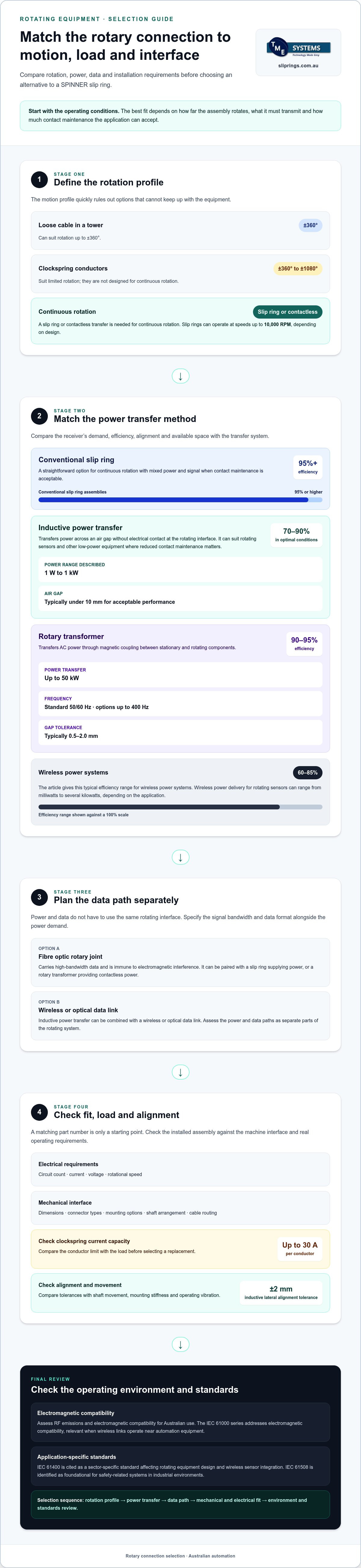
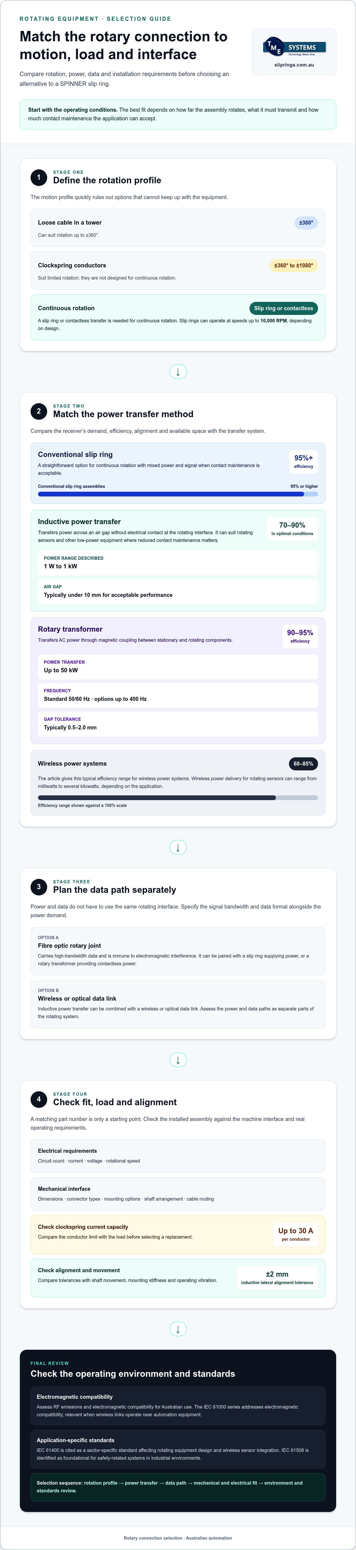
The obvious alternative to a SPINNER slip ring isn’t always wireless. A SPINNER slip ring alternative may use contactless power transfer or a flexible cable, but each limits rotation, power or data in a different way. Wireless power systems typically achieve 60% to 85% transmission efficiency, while conventional slip ring assemblies achieve 95% or higher.
It’s understandable to seek a way to reduce contact wear and maintenance. For continuous rotation with mixed power and signal, a slip ring remains a straightforward option when contact maintenance is acceptable. Contactless systems and cable routing through a hollow shaft can suit different operating conditions.
This article compares contactless transfer, wiring through a hollow shaft and wireless systems for rotating equipment. You’ll see where each approach fits, what can constrain it, and which application details matter when selecting a rotary electrical connection for Australian automation.
Key Takeaways
- Match the transfer method to whether the application needs continuous rotation or only limited movement.
- Assess power and signal requirements together, since a contactless power system may need a separate data link.
- Compare wireless suppliers by how their systems fit the machine’s operating conditions and integration needs.
- Use shaft dimensions, connector interfaces and mounting style to narrow down compatible rotary connections.
- Prepare the application details, including circuit count, current, voltage, speed and environment, to support a more informed selection.
Comparing alternatives by rotation, power and maintenance
The right SPINNER slip ring alternative depends on how far the assembly rotates, what it must transmit and how much contact maintenance the application can accept. Compare these requirements together rather than choosing on power transfer alone.
Rotation and Maintenance Considerations
Start with the motion profile. A loose cable inside a tower can suit rotation of ±360°, while clockspring conductors suit limited rotation from ±360° to ±1080° and aren't designed for continuous rotation. Continuous rotation needs a different approach, such as a slip ring or contactless transfer. Factor in access for inspection and the effect of contact wear on planned maintenance.
Slip rings can operate at speeds up to 10,000 RPM, depending on design. That figure isn't a substitute for matching the rotational speed rating to the actual load and operating conditions.
Inductive Power Transfer Options
Electromagnetic induction transfers power across an air gap, avoiding electrical contact at the rotating interface. For rotating sensors and other low-power equipment, inductive systems can suit applications where reduced contact maintenance matters. In optimal conditions, electromagnetic induction power transfer can achieve efficiencies of 70% to 90%, and systems typically require an air gap under 10mm for acceptable performance.
Inductive power transfer is described across power levels from 1 W to 1 kW. Check the receiver’s demand, alignment and available gap against the system design before treating contactless transfer as a direct replacement.
Replacement Compatibility and Specifications
To select a compatible replacement, use the part number as a starting point, then compare the electrical and mechanical specifications. Check circuit count, current, voltage, rotational speed, dimensions, connector types and mounting options against the installed assembly and machine interface. A matching part number alone does not confirm that the operating requirements align.
Record the shaft arrangement and cable routing as well. These details help distinguish an end-of-shaft unit from a through-bore arrangement and show whether a hollow shaft can accommodate the required wiring.
For wind turbines, assess power and data paths separately. Inductive power transfer can be combined with a wireless or optical data link; a fibre optic rotary joint can also carry data while a slip ring supplies power. IEC 61400 is cited as a sector-specific standard affecting rotating equipment design and wireless sensor integration. The IEC 61508 functional safety standard is identified by the International Electrotechnical Commission as foundational for safety-related systems in industrial environments.
For Australian use, assess RF emissions and electromagnetic compatibility alongside the installation, and treat import classification as a separate procurement consideration. The IEC 61000 series addresses electromagnetic compatibility, which is relevant when wireless links operate near automation equipment.
Current capacity also matters: clockspring conductors can carry up to 30 A per conductor, so compare this limit with the load before selecting a replacement.
Contactless power and data transmission for automation
Contactless systems separate electrical transfer from the rotating interface, which can suit sensors where wear at electrical contacts is a concern. The design still needs to match the sensor’s power demand, rotation, available space and data rate. Wireless power delivery for rotating sensors ranges from milliwatts to several kilowatts, depending on the application. That range makes the receiver load a practical starting point, not an afterthought.
Rotary transformers for contactless AC power transfer
A rotary transformer transfers AC power through magnetic coupling between stationary and rotating components. Rotary transformers can transfer up to 50 kW and typically achieve 90-95% efficiency. Standard operation is at 50/60 Hz, with options up to 400 Hz. These figures help frame a design review, but the required output, frequency and mechanical interface must all align with the equipment.
Gap control is a key design input. Rotary transformers typically have a gap tolerance of 0.5-2.0 mm, so mounting accuracy and mechanical movement matter. Inductive power transfer systems have a lateral alignment tolerance of ±2 mm. Engineers should compare these tolerances with shaft movement, mounting stiffness and operating vibration before selecting a coupling method.
For an AC-powered rotating assembly, map the full path from the fixed supply to the rotating load. Confirm the transformer’s input and output requirements, then assess how the receiver connects to the sensor or actuator. A rotary transformer can be paired with a fibre optic rotary joint when the rotating equipment also needs high-speed data. This separates the power and data paths, giving each interface a defined function.
Contactless data paths for rotating sensors
Specify data transfer separately. A fibre optic rotary joint suits high-bandwidth data and is immune to electromagnetic interference. It can carry data while a slip ring supplies power, or pair with a rotary transformer for contactless power and optical data. The choice depends on signal bandwidth, power demand and the required interface on each side of the rotating assembly.
For example, a rotating inspection sensor may need a stable power feed and a high-bandwidth stream to a fixed controller. List the sensor’s power demand, data format, rotation profile and receiver layout before comparing architectures. This makes the trade-offs clear: contactless power may reduce electrical contact wear, while optical data provides a separate route for signals.
Demand for contactless rotating sensors is application-led: the approach is relevant where sensor power or data must cross a rotating interface without a conventional electrical contact path. In automation, this can include measurement equipment and rotating inspection assemblies. Treat the system as an integrated design, not a standalone wireless component. Check alignment, frequency, power capacity and data interface together, then confirm that the arrangement suits the machine’s operating cycle.
Wireless slip ring suppliers
A wireless supplier may provide a contactless power system, a data link or both. Treat the offer as an interface for rotating equipment, not automatically as a like-for-like SPINNER slip ring alternative. First define what crosses the rotating boundary: power, sensor signals, control data or a combination. That scope determines which supplier capabilities matter.
Compare systems against the machine’s operating requirements. Assess how the proposed architecture handles continuous rotation, the required electrical load, data format, alignment and installation space. A system that transfers power wirelessly may still need a separate data path. For example, an inductive power unit can pair with an optical link when the sensor also sends high-bandwidth data.
Technical fit and integration
Request a system-level description covering the stationary transmitter, rotating receiver, data interface and mechanical arrangement. Check that the design accounts for the machine’s movement and alignment limits. For an automation cell, document how the rotating unit connects to the controller and how signals behave during rotation. This clarifies integration work before equipment selection.
Compare the stated operating limits with the application, not just the headline capability. Record the required power, rotation profile, data needs, available gap and mounting envelope in one specification. Then map each requirement to a proposed system component. This gives engineering and procurement teams a consistent basis for comparing wireless architectures without assuming that unlike systems are interchangeable.
Standards, environment and support
Industrial integration also involves electromagnetic compatibility and machine safety. The IEC 61000 series covers electromagnetic compatibility requirements relevant to wireless alternatives. ISO 12100 is cited in relation to mechanical safety and wireless sensor integration. IEC 62443 concerns cybersecurity in industrial automation systems, making network architecture and data handling relevant supplier discussion points.
For hazardous atmospheres, the research identifies ATEX (94/9/EC) and IECEx as relevant standards. Treat this as an application-specific design issue, not a blanket assurance about a supplier or system. Wind energy projects also have sector-specific design considerations associated with IEC 61400. Ask for the technical documentation that describes how the proposed arrangement fits its intended operating environment.
Supplier support should address the full interface, including power electronics, receiver installation, data path and machine controls. Clarify which party supplies each component and how the components connect. A written integration plan can identify cable routes, controller interfaces, alignment needs and commissioning checks before installation.
- Compare systems against the same operating specification.
- Separate power-transfer requirements from data-link requirements.
- Review EMC, safety, cybersecurity and environmental factors relevant to the application.
- Document component boundaries and integration responsibilities before procurement.
This process helps determine whether a wireless system meets the rotation and transmission requirements, or whether a contact-based rotary connection is more suitable.
What are the dimensions, connector types and mounting options for SPINNER-compatible alternatives?
A compatible alternative must fit the machine mechanically and connect to its existing wiring. Begin with the installed unit’s part number, drawing and available measurements. Record the body length, outside diameter, shaft or bore dimensions, mounting face and cable exit direction. For example, a replacement can match the electrical function yet interfere with a nearby guard if its body is longer.
Measure the available space around the rotating assembly, including clearance for connectors and cable bends. Compare the shaft centreline, fixing points and orientation against the equipment drawing. If no drawing is available, document the installed arrangement before removal, including photographs of mounting faces and cable routes. These records help engineers compare alternatives without relying on the part number alone.
Match the mounting arrangement
Mounting style determines how the connector attaches to the machine and accommodates movement. A through-bore slip ring has a hollow centre for installation over a shaft or routing auxiliary components. A capsule form mounts at the shaft end. Compare the shaft position, support method and available clearance before choosing between these layouts.
Check how the stator and rotor are restrained. The stationary side needs a secure reaction point, while the rotating side must follow the shaft without obstructing nearby equipment. For a flange-mounted assembly, compare the bolt pattern and face orientation. For a shaft-mounted unit, record the shaft interface and any required coupling or anti-rotation feature.
Confirm connector interfaces
Identify the installed terminations at both ends, such as plug-and-socket connectors, terminal blocks or cable tails. Record pin arrangement, wire identification and cable direction from the existing wiring diagram. Similar-looking connectors can have different pin assignments, so compare the interface documentation rather than relying on housing shape alone.
- Record each power and signal circuit, its function and termination.
- Compare connector orientation and access for installation tools.
- Note cable length, routing and clearance around moving parts.
- Keep the existing wiring diagram with the replacement measurements.
Electrical compatibility matters as much as physical fit. Compare circuit count, current, voltage and signal requirements with the machine’s operating specification. A unit with the correct outline may still lack an independent path for a required signal. Separate power and signal circuits in the comparison sheet, then match each one to its intended terminal or connector.
Environmental and operating details also affect selection. Note the installation location, exposure to dust or moisture, operating temperature and rotational speed requirement. Use the machine documentation to identify the required IP rating and operating conditions. For Australian installations, keep the existing electrical design documentation with the equipment record so the replacement review considers both wiring interfaces and mechanical mounting.
A useful cross-reference package combines the part number, dimensional drawing, connector details, mounting photographs and circuit schedule. This gives an engineer a clear basis for assessing a SPINNER-compatible alternative and identifying interface changes before installation.
Evaluating SPINNER-compatible alternatives in Australia
Assess a replacement as an engineering change, not simply a part substitution. Begin by defining the machine function the rotary connection supports, such as transferring sensor signals on an indexing table or power to a rotating assembly. This identifies what must remain unchanged and where a different connector design could affect the equipment.
Use a structured review before approving a substitute. First, collect the existing component documentation and equipment records. Next, compare the proposed unit’s data with the original application requirements. Finally, record any differences and decide whether they affect machine operation, installation or maintenance. This gives engineering, maintenance and procurement teams a shared basis for approval.
Separate direct matches from design changes. A direct match preserves the existing interface and function. A design change may require revised brackets, cable routing, electrical drawings or installation instructions. Record each difference against the relevant machine drawing or document, and assign it to the responsible engineering reviewer. This creates a clear record for future maintenance and avoids relying on informal handover notes.
Assess the operating scenario, not just the equipment name. A rotary table that indexes between positions has a different motion pattern from a continuously rotating assembly. A sensor carrying a single measurement signal also differs from a device combining control and power. Describe the actual duty cycle and system function, then use that information to judge whether the replacement meets its intended use.
- Identify the equipment and the function served by the rotary connection.
- Gather the current component records and relevant machine drawings.
- Document any interface or installation differences in the proposed replacement.
- Route the technical change to the appropriate engineering reviewer.
- Update the equipment record after approval and installation.
Keep the decision traceable. The approval record should identify the selected component, the application documents reviewed and any machine changes. If the replacement changes the wiring or mechanical arrangement, update the corresponding drawings and maintenance instructions. Future technicians can then understand the installed configuration without relying on the old component label.
For Australian automation projects, this disciplined approach helps teams compare alternatives consistently across sites and equipment types. It also makes a later replacement review easier, because the reasons for the original selection and any accepted design changes remain documented. Use the same review steps for each candidate, and base approval on its fit with the machine’s defined function and operating conditions.
TME Systems: Mercotac Slip Rings
TME Systems helps Australian automation teams compare rotary electrical connectors against their application requirements. Its range includes Mercotac Slip Rings, Meridian Laboratory Slip Rings, BGB Innovation Slip Rings and Prosper Rotation Slip Rings. Technical application consulting can help narrow the selection using circuit count, current, voltage, speed, mounting style and environmental conditions.
Bring the existing part number, equipment drawing and operating requirements to the comparison. These details help clarify whether a replacement must match the existing footprint or whether the application can accommodate a different configuration. If you’re assessing a SPINNER slip ring alternative, TME Systems can help match the technical requirements to its slip ring offerings.
Contact TME Systems to discuss your application.
Turn your comparison into an engineering brief
Make the next step a clear engineering decision. Assess a SPINNER slip ring alternative against the machine’s intended function, with acceptance criteria agreed before procurement. This keeps the decision focused on operational needs and gives the project team a practical basis for reviewing its selection.
A concise brief also supports a smoother handover between engineering, procurement and maintenance. Record the reason for the choice and the conditions the selected assembly must meet, giving future project decisions a useful reference point.
Discuss your options with TME Systems and move your application review forward with confidence.
Frequently Asked Questions
Which manufacturers offer alternatives to SPINNER slip rings in Australia?
Australian buyers can source alternatives from manufacturers of brushless rotary connectors and industrial slip-ring assemblies. Product ranges differ by construction and intended application, so a manufacturer-level cross-reference alone does not establish interchangeability. Compare technical documentation with the required operating conditions and function. Then shortlist specific models whose documented capabilities suit the equipment, rather than assuming similar product descriptions indicate equivalent performance.
What power ratings, channel counts and rotational speeds are available from competing slip rings?
Typical market figures include current capacities of 1-500 A per ring and voltage ratings up to 1000 V AC/DC, but these aren’t universal specifications. Channel count and rotational speed depend on the design and model. Contact resistance is typically described as 1-10 mΩ. For selection, compare the individual model’s rated values with the load and signal paths required by your equipment.
Where can Australian buyers purchase SPINNER slip ring alternatives and get local technical support?
Australian buyers can approach TME Systems for product sourcing and technical application consulting. For a focused discussion, describe the equipment’s role, project stage and any constraints on integrating a replacement into the control system. This frames the selection conversation around the application rather than a general request for an equivalent component, and gives procurement and engineering teams a shared starting point.
What are the reliability, service-life and maintenance risks of replacing a SPINNER slip ring?
Commissioning can expose problems that a specification comparison alone won’t reveal. Incorrect termination or signal compatibility may cause intermittent readings, control faults or data errors during operation. Check every connected circuit and signal under the machine’s normal operating cycle. Record the results and any control-setting changes in the equipment documentation, so later fault-finding starts from the tested configuration rather than assumptions.