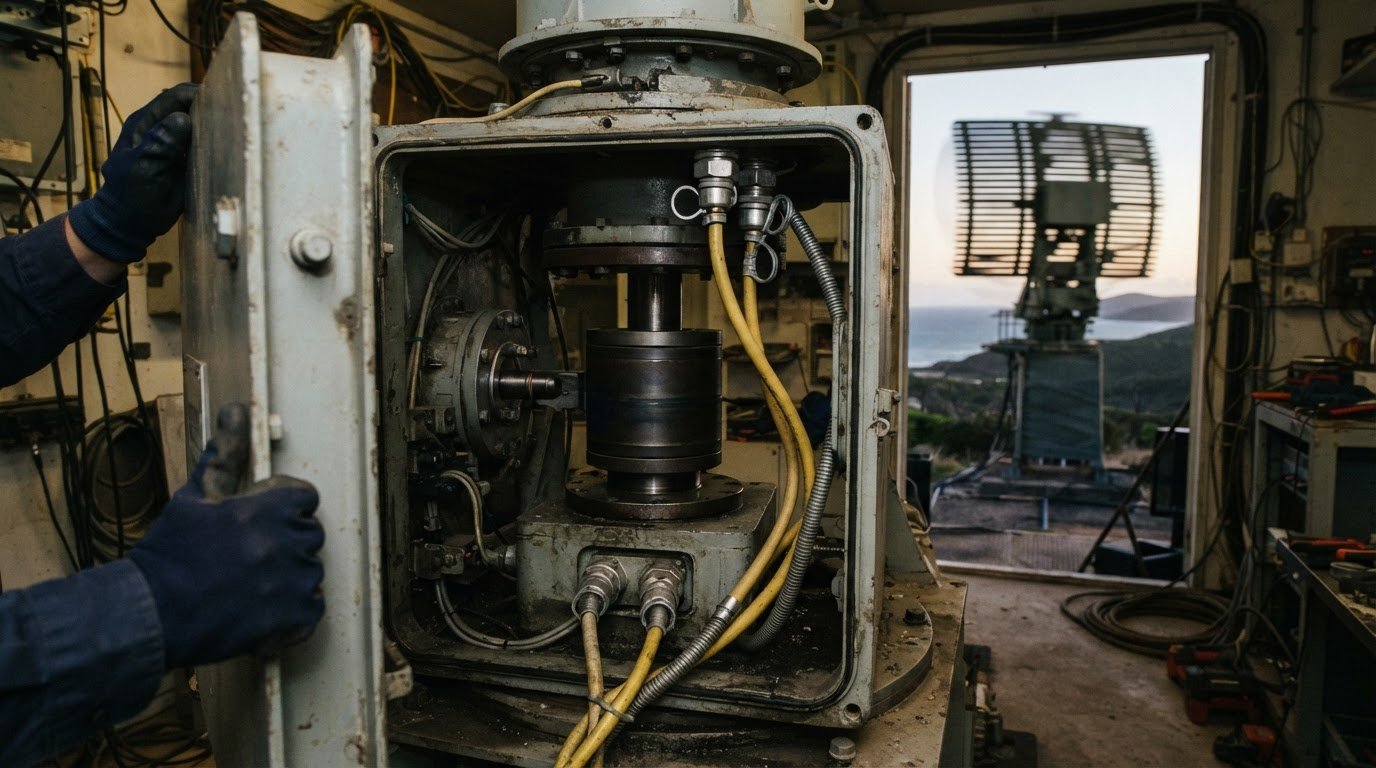
A rotating system doesn’t always need a wireless link: a fibre-optic rotary joint can carry data across a continuously rotating interface. The choice between wireless data transmission and a fibre-optic rotary joint depends on the equipment’s movement, signal requirements and operating environment.
Both approaches can suit demanding applications, but they solve different problems. Wireless transmission avoids a physical data connection across the rotating interface, while a fibre-optic rotary joint maintains an optical path as equipment turns through 360 degrees. That distinction matters in radar, wind turbines, robotics and remotely operated equipment, where reliable data transfer must work alongside mechanical movement.
This article explains where fibre-optic rotary joints are used and how they compare with wireless transmission in practical engineering terms. It covers how each method handles rotation, electromagnetic interference, bandwidth and system integration, and which requirements should guide your decision. The aim is to help you identify the right approach for your application, rather than assume one technology suits every installation.
Key Takeaways
- See how a fibre-optic rotary joint carries data across a rotating interface, and why continuous rotation, signal loss and speed requirements matter.
- Explore how rotary optical connections support applications such as wind turbines, drones, robotics and radar.
- Understand why fibre-optic data transmission is immune to electromagnetic interference, and how that can affect system design in electrically noisy environments.
- Compare wireless transmission with a physical optical connection by considering movement, signal needs and operating conditions.
- Learn how slip ring technologies, mounting options and technical application consulting can help match a rotary connection to an engineering application.
What is a fibre optic rotary joint?
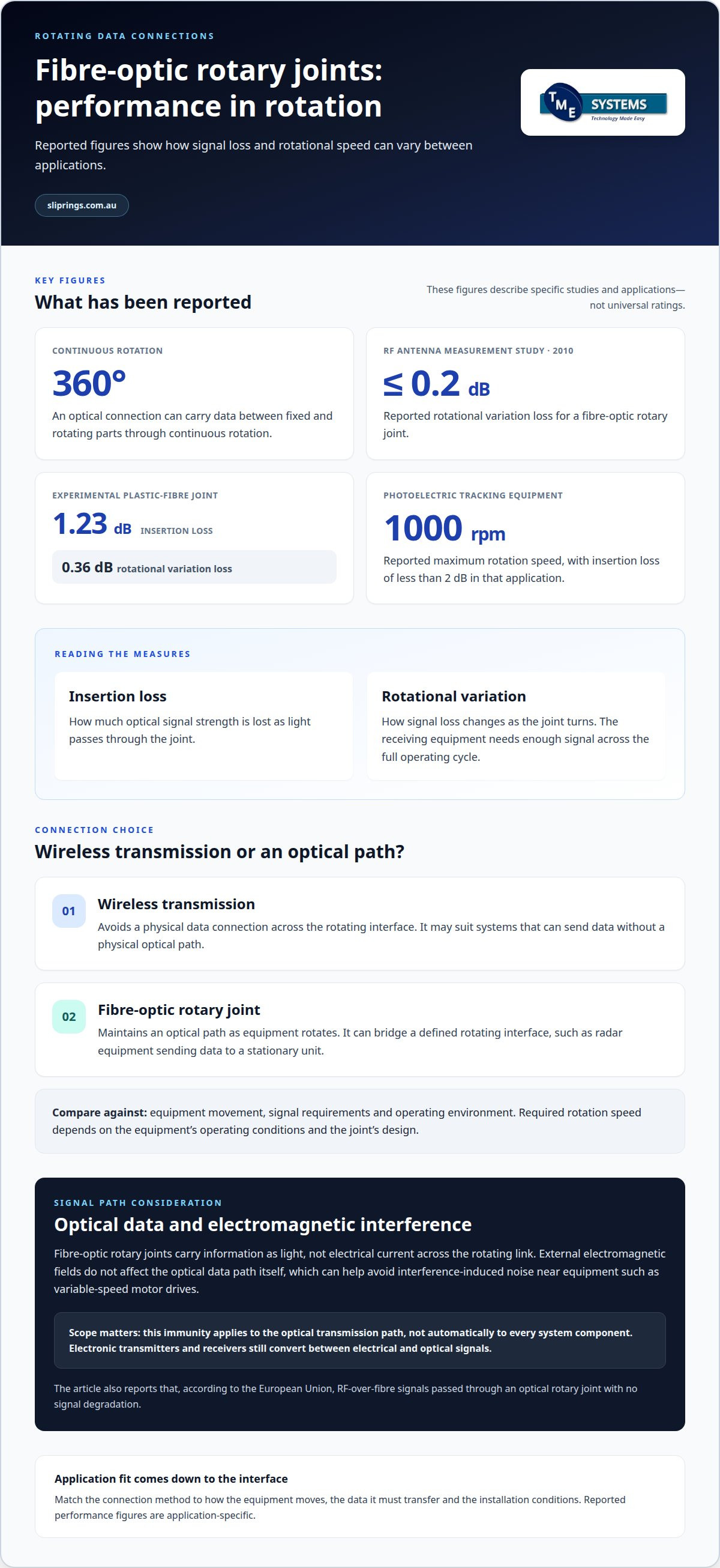
A fibre-optic rotary joint transfers optical data between stationary and rotating components while maintaining a light path. Its performance depends on signal loss, rotational variation and operating speed.
Data transfer across rotating interfaces
At the interface, lenses or prisms guide light from a stationary fibre into a rotating optical path. The signal then reaches a fibre connected to the moving assembly. Some single-channel units convert electrical data, such as Ethernet, into optical signals before transmission. This lets equipment pass data while rotating, without winding a data cable around its shaft. Correct optical alignment supports consistent coupling across the interface.
Insertion loss and rotational variation
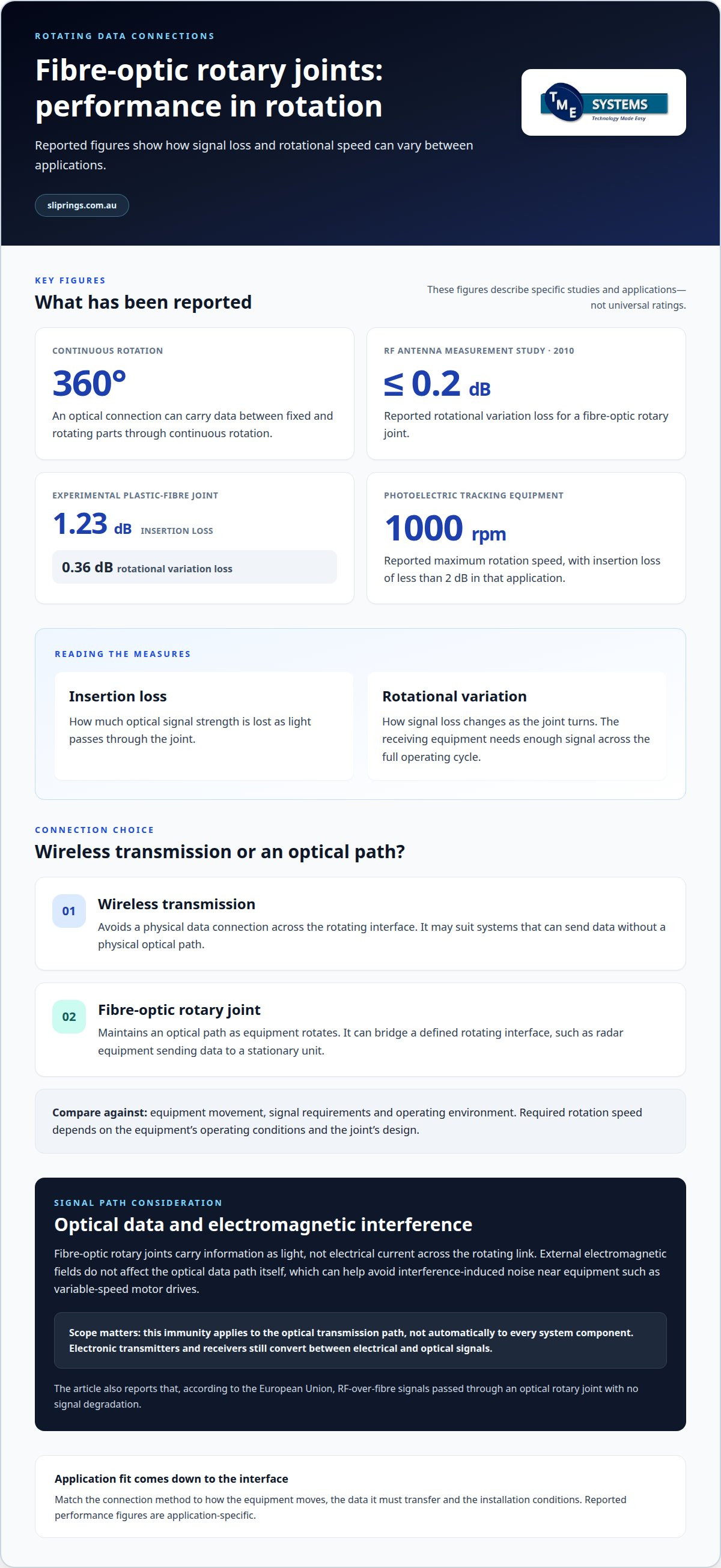
Insertion loss measures how much optical signal strength is lost as light passes through the joint. Rotational variation describes how that loss changes as the joint turns. Both matter because the receiving equipment needs enough signal across the full operating cycle. A 2010 IEEE study of a fibre-optic rotary joint for RF antenna measurement demonstrated rotational variation loss of 0.2 dB or less. An experimental plastic-fibre joint reported 1.23 dB insertion loss and 0.36 dB rotational variation loss.
Continuous rotation and speed requirements
A rotary joint can maintain an optical connection through continuous 360° rotation, allowing data to pass between fixed and moving parts. The required rotation speed depends on the equipment’s operating conditions and the joint’s design. A photoelectric tracking equipment application reported insertion loss of less than 2 dB and a maximum rotation speed of 1000 rpm. These figures describe that application, not a universal rating. Matching speed and signal requirements helps engineers assess suitability for a specific rotating system.
Applications in wind turbines, drones, robotics and radar
Fibre-optic rotary joints suit equipment that must exchange data between stationary and rotating sections. In a wind turbine, sensors on rotating blades can send operating data to stationary control systems through the joint. The optical path avoids routing a conventional cable that would twist as the rotor turns. This supports monitoring across the rotating interface while integrating the data connection with the turbine’s mechanical design.
Tethered drones and remotely operated vehicles can carry video and data through connections that move or rotate. Where a tether passes through a rotating interface, a fibre-optic rotary joint can maintain the signal path as the equipment changes orientation. This is useful when operators need information from a moving platform without interrupting the connection during rotation. The joint addresses the rotating interface, rather than replacing the tether itself.
In robotics, rotary joints can transfer signals between fixed equipment and moving robot sections. This can suit a robot whose arm or platform rotates while exchanging control or sensor data. Radar systems provide another example: a joint can pass surveillance data from rotating equipment to a stationary display or interrogation unit. The connection lets the radar assembly turn while the receiving equipment remains fixed.
Which option suits industrial robots, wind turbines, radar or rotating machinery? A fibre-optic rotary joint is relevant when data must cross a rotating interface; wireless transmission may suit systems that can send data without a physical optical path. The right choice depends on the equipment’s movement, data requirements and installation constraints. For example, radar sending surveillance data to a stationary unit has a defined rotating connection to bridge, while a tethered remotely operated vehicle may need data to travel along its tether.
Electromagnetic interference immunity
Fibre-optic rotary joints carry information as light, not electrical current across the rotating link. That distinction matters near equipment producing electromagnetic interference (EMI), such as variable-speed motor drives. External electromagnetic fields do not affect optical data transfer itself. The optical path can therefore avoid interference-induced noise in the rotating data connection.
Electrical connections carry signals through conductors, where electromagnetic fields can introduce unwanted noise. An optical fibre carries light instead, so the rotating fibre link provides no conductive path for that interference. This can help preserve signal integrity beside switching equipment or where several electrical systems operate together. The benefit is specific: external electromagnetic fields do not affect the optical data path.
Fibre optics can also carry radio-frequency signals through a rotating optical joint. According to the European Union, RF-over-fibre signals passed through an optical rotary joint with no signal degradation. This example shows how an optical connection can transport signals through a rotating interface without the interference and noise issues that may affect traditional electrical connections.
This immunity applies to the optical transmission path, not automatically to every component in the system. Electronic transmitters and receivers still handle conversion between electrical and optical signals. Their placement, cabling and connections remain relevant to system design. Separating the optical span from susceptible electrical sections helps clarify where EMI protection is needed.
For a rotating machine operating near electrical noise sources, a fibre link offers a direct way to prevent EMI from affecting data transfer across the joint. Wireless links also avoid a conductive data cable, but transmit through radio rather than guided light. The choice depends on whether the installation needs a defined optical path through the rotary interface or can support a wireless link. Assess the signal route and nearby equipment together.
Environmental and mechanical requirements
A rotary joint must suit its installation environment and the machine’s movement. A unit mounted inside an enclosed radar housing faces different exposure from equipment installed on an outdoor wind turbine. Temperature changes, dust, moisture and vibration can affect the assembly, its optical alignment and its connections. The enclosure, cable routing and mounting arrangement are therefore part of the application design.
Mechanical fit starts with the rotating shaft and available space. A joint must align with the stationary and rotating optical paths, while its mounting supports the intended movement. In a robot, for example, the connection must fit the rotating axis without restricting the arm’s travel. Tethered remotely operated equipment may need a different layout, particularly where the optical link sits beside a moving tether.
Operating speed and duty cycle also matter. A radar antenna that rotates continuously places different demands on its joint from machinery that turns only for occasional positioning. Rotation speed must remain within the joint’s specified rating, and the design must account for operating patterns, acceleration and vibration. These mechanical conditions can affect optical alignment and signal consistency during movement.
Environmental protection should match actual exposure, not a general description of the site. An outdoor installation may face dust and moisture, while equipment in a processing area may experience heat or nearby vibration. An IP rating describes protection against dust and water ingress, but does not establish suitability for every operating condition. Engineers assess the enclosure, mounting, shaft interface, cable path and environmental exposure together. This avoids treating the rotary joint as an isolated component and helps identify how the surrounding machine affects its operation.
Wireless data transmission compared with fibre-optic rotary joints
Wireless links send data through radio, while fibre-optic rotary joints guide light across a rotating interface. The better fit depends on signal requirements, machinery movement and the installation environment.
Performance in noisy and harsh environments
In electrically noisy settings, fibre-optic transmission prevents electromagnetic interference from affecting the optical data path. Wireless transmission has no physical data cable across the rotating interface, but its radio link can be affected by competing signals or obstructions. According to the European Union, RF-over-fibre signals passed through an optical rotary joint with no signal degradation. For rotating machinery, the distinction is practical: optical joints provide a guided connection, while wireless systems need a usable radio path.
Wireless reliability and safety risks
Wireless reliability depends on signal coverage, interference and the connection between moving equipment and its receiver. A blocked or disrupted link can interrupt data from a robot or rotating machine. Wireless signals can also be exposed to unauthorised access, so cybersecurity controls matter when transmitted information is sensitive. If data supports a safety-related function, communication interruptions must be considered in the system’s safety design. An optical joint avoids radio-link exposure across its interface, but still requires suitable components and installation.
For Australian installations, AS/NZS 3000:2018 is the Australian/New Zealand wiring rules standard for electrical installations. It provides an installation reference, not a universal requirement to choose wireless or optical data transmission.
Choose wireless when the system can maintain its radio link and needs no physical data path through the rotating interface. Choose a fibre-optic rotary joint when equipment needs a guided optical connection across continuous rotation, particularly where electromagnetic interference threatens data transfer. In either case, assess the data’s role, movement, signal route and operating environment together.
Slip ring technologies and mounting options
A rotary electrical joint transfers power or signals between stationary and rotating equipment. Slip rings provide electrical paths across that interface, while a fibre-optic rotary joint carries optical data. The right assembly depends on whether the application needs electrical continuity, optical transmission or both.
Collector rings are heavy-duty rotary connectors designed for high current capacity, whereas standard slip rings are typically optimised for signal integrity and lower currents. Liquid metal rotary connectors are brushless rotary connectors that use a pool of conductive liquid metal to maintain electrical continuity, eliminating wear and reducing noise. These technologies address different electrical transfer requirements, so current demand and signal type shape the selection.
Mounting affects how the joint integrates with the machine. A through-bore slip ring has a hollow centre for mounting over a shaft or accommodating auxiliary components such as hydraulic lines. A capsule slip ring has a compact solid form for end-of-shaft mounting. Shaft dimensions, available space and the position of existing services influence which configuration suits the equipment.
Prosper Rotation slip rings are an option for applications requiring a rotary electrical connection. Their suitability depends on the system’s electrical paths, mounting arrangement and operating conditions, not the product category alone. A design review can account for the required circuit count, shaft interface and space around the rotating assembly.
For example, a machine with a central shaft and hydraulic lines may call for a hollow mounting arrangement, while an end-of-shaft installation may favour a capsule format. If the system transfers substantial current, a collector ring may be more relevant; for optical data, an electrical slip ring does not replace a fibre-optic rotary joint. Matching the rotary connection to the function prevents the mounting format from dictating an unsuitable transmission method. Explore Prosper Rotation slip rings as part of that assessment.
Technical application consulting and engineering support
Technical application consulting helps assess which rotary connection suits a machine’s electrical and mechanical requirements. The review starts with the data path: whether the system needs power transfer, electrical signals, optical data or a combination. It also considers how the rotating and stationary components connect, so the selected technology addresses the actual interface rather than an assumed one.
Application engineering brings operating conditions into the assessment. Relevant details include the shaft arrangement, available mounting space, rotation pattern, required circuit count and surrounding environment. For example, a shaft with auxiliary services passing through its centre may need a different mounting format from an end-of-shaft installation. Speed and signal requirements also help distinguish an electrical slip ring from an optical rotary joint.
A final engineering review can bring these design factors together before a rotary connection is integrated into the equipment. It can examine interface dimensions, electrical requirements, signal paths and operating conditions as one system. This helps identify compatibility questions early, such as whether the connection must carry both power and data or whether separate rotary components are needed. Clear application details make the assessment more specific.
Technical Application Consulting can help assess slip ring options, including Mercotac® connectors, Meridian Laboratory - ROTO-CON connectors and Prosper Rotation slip rings. These products address rotary electrical connection requirements; they do not replace a fibre-optic rotary joint when optical transmission across rotation is required. The appropriate option depends on the function, mounting arrangement and operating conditions. TME Systems works with manufacturers that offer standard and customised solutions, selecting each manufacturer for a different strength to match the right technology to the application.
TME Systems
TME Systems helps assess rotary connection requirements through Technical Application Consulting and relevant slip ring options. This is a practical next step when a machine needs data or power transfer across a rotating interface and you are still evaluating wireless transmission, optical transfer and electrical connection. The key distinction is functional: a slip ring transfers electrical power or signals, while a fibre-optic rotary joint carries optical data.
The assessment can consider the machine’s movement, electrical requirements, signal paths, shaft arrangement and mounting space. These details help establish whether an electrical slip ring addresses the application or whether the data path calls for a separate optical or wireless approach. A system that needs electrical continuity across a rotating shaft has different requirements from one carrying optical data through that interface.
TME Systems Pty Ltd offers Mercotac Slip Rings, Meridian Laboratory Slip Rings and Prosper Rotation Slip Rings. Mercotac connectors are compact, brushless and mercury-wetted, with low resistance and low noise for power and signal transfer. Meridian Laboratory ROTO-CON connectors are designed for high-current, high-speed and through-bore applications. Prosper Rotation offers standard and custom slip rings, including fibre-optic rotary-joint options.
Technical Application Consulting can help relate these options to the application’s requirements, rather than treating one slip ring type as suitable for every machine. A review can focus on what must pass across the rotating connection, how the assembly mounts and the conditions in which it operates. AS/NZS 5368:2025 can be included in the standards discussion where relevant to the project, without assuming it determines the choice of rotary connection.
To discuss your rotary connection application, contact TME Systems Pty Ltd.
Frequently Asked Questions
What applications are they used for?
Fibre-optic rotary joints support data transfer in wind turbines, radar, tethered drones and remotely operated vehicles. They also appear in robot, remote-control, military, aviation and submarine equipment. In each case, they address a rotating or moving connection between equipment sections. The application determines whether the optical joint carries operational data, video or another signal, and whether electrical power needs a separate rotary connection.
How does wireless data transmission compare with a fibre optic rotary joint?
Wireless transmission sends data by radio, while a fibre-optic rotary joint transfers optical signals across a rotating interface. Wireless can suit equipment where a physical optical path is impractical and a reliable radio path is available. A rotary joint suits designs that need a guided connection through rotating equipment. The decision turns on system layout, data requirements, the surrounding environment and whether the moving interface needs a physical connection.
What are the typical data rates and latency of wireless links versus fibre optic rotary joints?
There is no single typical data rate or latency that applies to every wireless link or optical rotary joint. Wireless performance depends on the radio system and operating conditions; optical performance depends on the joint and connected equipment. Fibre systems can support high-bandwidth data, but the complete link’s capacity and delay also depend on conversion and processing equipment. Compare the required application performance with the specifications of the complete transmission path.
What are the maximum transmission distance and signal-loss limits for each option?
Wireless range depends on the radio equipment, signal path and surrounding obstructions, so one maximum distance does not apply to every installation. Fibre-optic connections can transmit data over distances greater than 100 kilometres, but that figure does not define a rotary joint’s own limit. A joint contributes signal loss within the complete optical path. The design must account for the transmission distance, connection interfaces and receiver requirements.
How do fibre optic rotary joints handle bandwidth, rotation speed and number of optical channels?
Bandwidth, rotational speed and channel count depend on the selected joint and connected system. Multi-channel designs can carry separate optical paths, and a published system demonstrated up to 21 parallel single-mode channels. This can support channel separation or redundancy. Rotation speed remains a design constraint, not a universal rating. Assess channel needs and operating speed together, then consider how the joint’s optical performance fits the equipment’s full data path.
What factors should be considered when choosing between wireless transmission and a fibre optic rotary joint?
Start with the data’s purpose, required continuity and the equipment’s movement. Then consider whether a radio path can remain usable or whether data must cross a defined rotating interface. Assess nearby interference sources, physical routing, mounting space, environmental exposure and the consequences of a communication interruption. Also identify whether the connection must carry power as well as data, since that may require a separate rotary electrical connection.