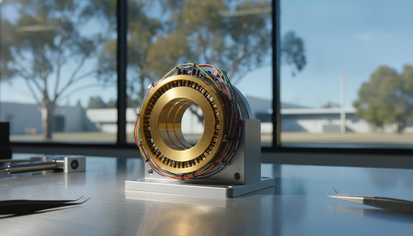
Adding "spare" circuits to a rotary union might seem like cheap insurance, but in high-precision engineering, it's often the primary cause of signal degradation and premature mechanical failure. Over-specifying your rotary connection doesn't just inflate costs; it increases internal friction and creates tighter packing densities that invite electromagnetic interference. Getting your slip ring circuit count selection right is a critical exercise in balancing current capacity against the need for clean data transmission.
We understand the challenge of managing signal noise while trying to fit complex wiring into tight housing constraints. This guide provides a technical blueprint to help you audit your system requirements and determine the exact number of channels needed for reliable performance. You'll learn how to categorise power and data lines to prevent crosstalk and how to apply Australian standards like AS 60034.1:2023 to your hardware selection. We'll also examine how specialised components from Mercotac, Meridian Laboratory, and BGB Innovation can be configured to optimise your rotary system for the long term. By the end of this article, you'll have the technical framework required to select a reliable, long-life rotary connector that meets your specific environmental and electrical demands.
Key Takeaways
- Understand the critical relationship between circuit density and mechanical performance to prevent excessive torque and premature wear in your rotary systems.
- Learn how to categorise channels by separating high-current power from sensitive data circuits to eliminate signal noise and electromagnetic interference.
- Follow a systematic auditing process for slip ring circuit count selection to ensure every rotating load and communication protocol is accurately mapped.
- Evaluate how physical housing constraints, such as through-bore or pancake designs, dictate the maximum number of circuits your application can reliably support.
- Identify when to specify specialised hardware from brands like Mercotac or BGB Innovation to meet the rigorous demands of Australian industrial environments.
Why Circuit Count is the Critical Baseline for Slip Ring Specification
A circuit in a rotary connector is the discrete electrical pathway that allows current or data to flow between the stationary and rotating components. Before looking at environmental ratings or mounting styles, slip ring circuit count selection serves as the primary technical baseline. If you miscalculate this number, you risk either an oversized unit that won't fit your assembly or a congested design prone to electrical failure.
In the Australian mining and defence sectors, precision auditing of these circuits is non-negotiable. Defence applications often involve high-frequency telemetry and power for turret systems, while mining equipment relies on heavy-duty sensors for real-time monitoring. For a foundational overview of the hardware components involved, you can read more about What is a Slip Ring? at Wikipedia. Selecting the wrong count often leads to specific operational failures:
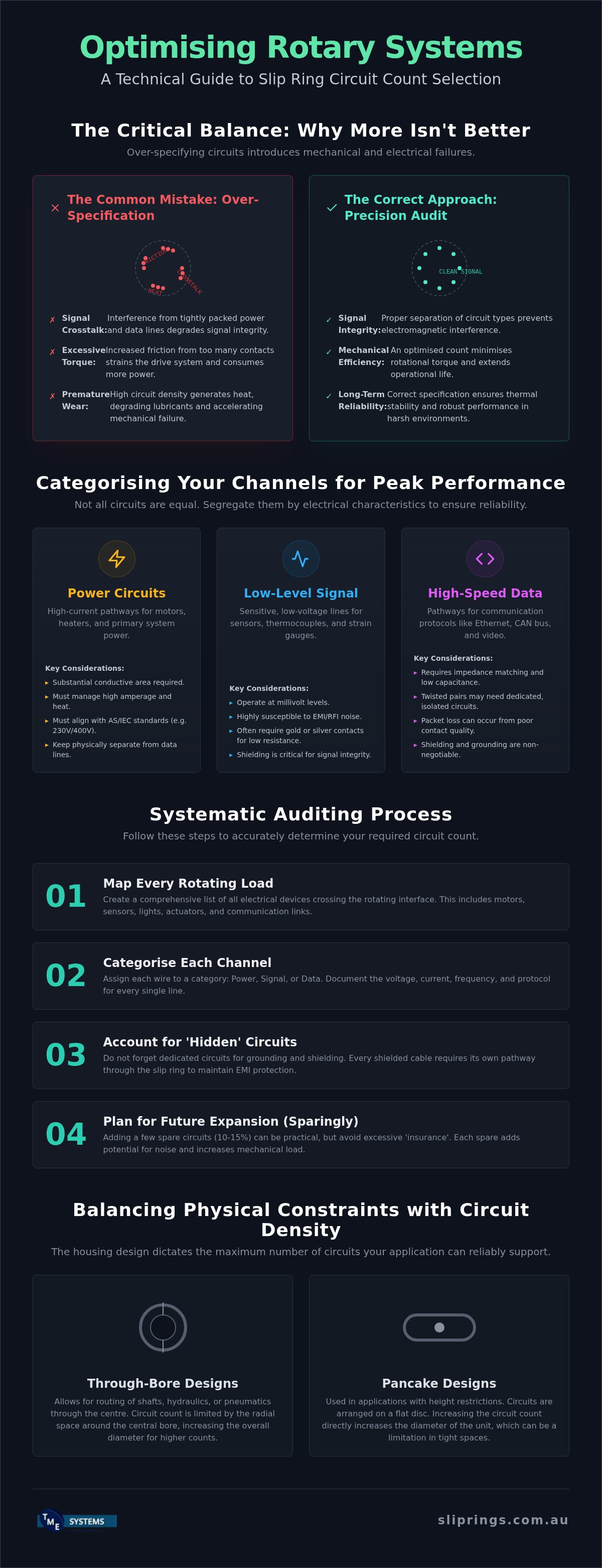
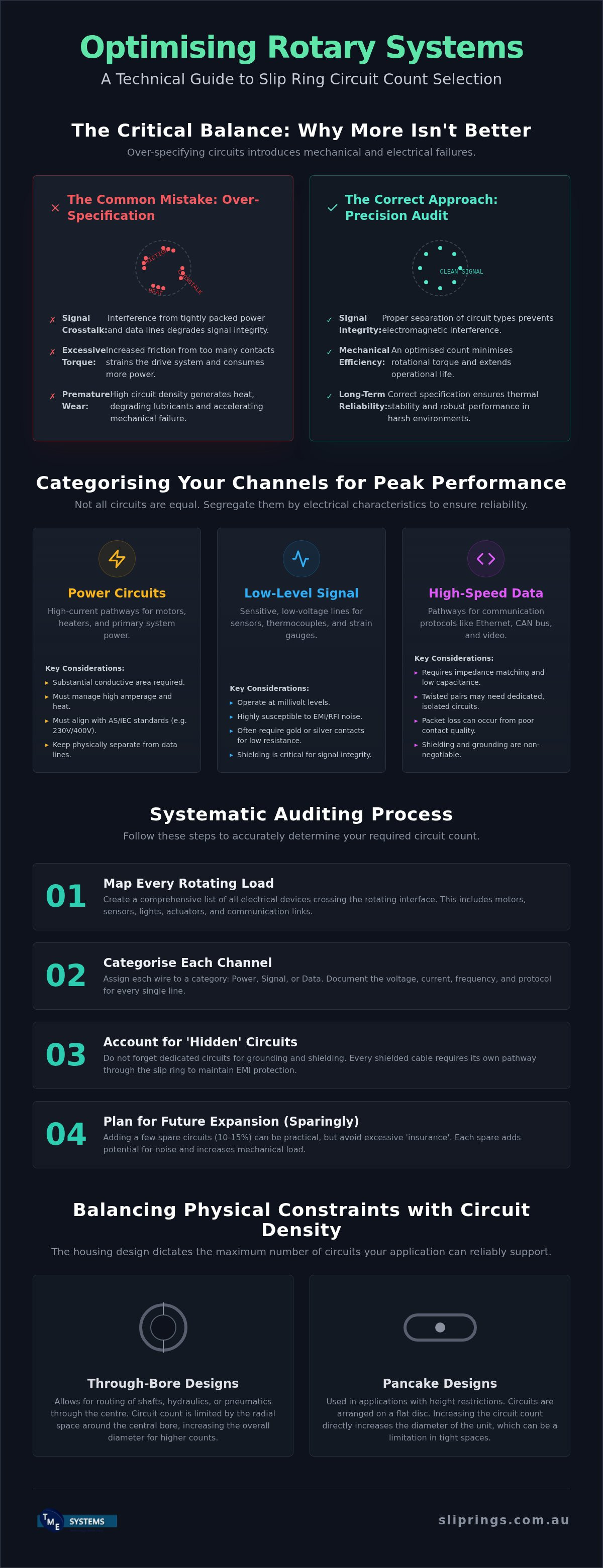
- Signal crosstalk: Interference between adjacent power and data lines.
- Excessive torque: Increased friction from additional brush contacts straining the drive system.
- Premature wear: Accelerated degradation of contact surfaces due to improper circuit density.
The Impact on Mechanical Footprint
When evaluating slip ring circuit count selection, engineers must prioritise the mechanical footprint. As the number of circuits increases, the physical dimensions of the slip ring must expand to accommodate the additional rings and brushes. This isn't just about length; the diameter often grows to maintain sufficient insulation between pathways. In weight-sensitive applications like robotic arms or aerospace telemetry, every gram matters. High circuit density requires a careful balance. You need enough space to prevent electrical arcing, yet the unit must remain compact enough to avoid excessive mechanical torque that can strain the drive motor.
Reliability and Signal Integrity
Incorrect circuit counts often lead to packing wires too tightly. This proximity creates electrical noise, especially when high-current power lines sit adjacent to sensitive control logic. Thermal management also becomes a factor. More circuits within a single housing generate more internal heat due to contact resistance. If heat isn't dissipated effectively, the lubricant can degrade, leading to premature wear and mechanical failure. Circuit crosstalk in rotary connectors refers to the unwanted transfer of signals between adjacent conductive pathways caused by electromagnetic or inductive coupling.
For high-speed data or sensitive signals, Mercotac Slip Rings provide liquid metal contacts that offer superior signal integrity compared to traditional brush designs. Alternatively, for heavy-duty industrial environments where high circuit counts are common, BGB Innovation Slip Rings are engineered to handle the mechanical stresses of the Australian resource sector.
Categorising Your Channels: Power, Signal, and Data Circuits
Effective slip ring circuit count selection requires more than a simple tally of wires. You must audit the electrical characteristics of every pathway to determine how they interact within the rotating assembly. Misclassifying a high-speed data line as a general signal channel often leads to packet loss, while underspecifying power circuits can result in thermal runaway. A successful specification treats each channel type as a distinct technical requirement with its own shielding and contact needs.
High-current power circuits demand substantial conductive area to manage amperage without excessive heat. In Australia, these must align with AS IEC 60038:2022 standards for 230V or 400V systems, accounting for the +10% voltage tolerance. Conversely, low-level signal circuits for thermocouples or strain gauges operate at millivolt levels. These are highly susceptible to electromagnetic interference from adjacent power lines. Grounding and shielding represent the "hidden" circuits often overlooked. Every shielded cable requires a dedicated pathway through the slip ring to maintain the integrity of the Faraday cage. Omitting these from your initial count often leads to intermittent signal dropouts that are notoriously difficult to diagnose.
Power vs. Signal Isolation
Separating power and signal channels is the most effective way to ensure precision instrumentation remains accurate. For applications requiring near-zero electrical noise, such as sensitive laboratory equipment or high-resolution sensors, Mercotac Slip Rings are the industry standard. Their liquid metal contact technology provides a constant, low-resistance connection that traditional brush and ring systems cannot match. This isolation prevents the "brush bounce" that typically introduces noise into low-voltage signal paths, ensuring that control logic remains stable even at high rotational speeds.
Specialised Data Requirements
Modern Australian manufacturing lines increasingly rely on high-speed data protocols like EtherCAT, Profinet, or USB 3.0. These channels have strict requirements for contact resistance and impedance matching. Gold-on-gold contacts are frequently used in these scenarios to maintain a stable connection over millions of rotations. In rotating radar or CCTV systems, high-frequency signals require specialised internal shielding to prevent crosstalk between channels. When you are mapping out these complex requirements, it is often helpful to seek technical application consulting to ensure your final specification handles both the mechanical and electrical loads of your specific project.
Step-by-Step: Auditing Your Equipment for Circuit Count Selection
Performing a thorough audit is the only way to ensure your slip ring circuit count selection aligns with the operational reality of your machinery. This process begins by listing every single rotating electrical load. You must document the peak current, nominal voltage, and duty cycle for each motor or heater. For instance, a three-phase motor requires three dedicated power circuits, while a single-phase heater might only need two. Accuracy at this stage prevents the common mistake of under-specifying current capacity, which often leads to overheating and insulation breakdown.
Next, map your control signals and communication protocols. Modern Australian industrial systems rarely use simple on/off logic; they rely on complex data streams like Modbus, EtherCAT, or Profinet. These digital signals often require twisted-pair or shielded wiring, which effectively doubles the circuit count for that specific data stream. You should also consider redundancy. In remote mining operations where downtime costs thousands of dollars per hour, including redundant circuits for critical sensors is a standard reliability strategy. If you're unsure how to group these channels, consult with a technical expert to determine which signals can be consolidated and which must remain separate to avoid noise interference.
Mapping the Electrical Architecture
Start by creating a formal circuit schedule that categorises lines as "dirty" (high-current power) or "clean" (sensitive data). This separation allows engineers to organise the internal layout of the slip ring to minimise electromagnetic interference. Verify the frequency of AC signals, as higher frequencies may require specific coaxial connections rather than standard rings. It is essential to develop a comprehensive checklist that accounts for every grounding and shielding requirement to maintain electrical safety and signal integrity across the rotary interface.
Future-Proofing Your Specification
While it's tempting to specify the exact number of circuits needed today, this approach can be short-sighted. Adding a buffer of spare circuits during the initial design phase is often more cost-effective than replacing the entire unit when you upgrade sensors or add a new camera. Weigh the higher upfront cost of a high-density unit against the long-term flexibility it provides. For complex systems, modular designs allow for easier expansion, whereas fixed-count units offer a more compact footprint. For a deeper dive into these technical trade-offs, refer to our resource on Slip Ring Application Engineering.
Balancing Physical Constraints with Circuit Density
Physical space is the ultimate arbiter in slip ring circuit count selection. While an electrical audit might reveal a need for dozens of channels, the mechanical reality of the machine often imposes strict limits on diameter, length, and weight. Engineers must choose between capsule designs for compact, low-current tasks or through-bore models when a shaft or fluid line must pass through the centre. Each ring added to a through-bore unit increases the axial length. This can lead to cantilever issues if the mounting isn't perfectly aligned.
Pancake slip rings offer an alternative for height-restricted applications. By arranging the conductive rings on a flat, horizontal plane, they solve vertical clearance issues. However, this configuration often limits the maximum circuit count because the outermost rings have a much higher surface speed than the inner ones. This differential leads to uneven wear and potential signal degradation on the outer channels. Environmental sealing also plays a role. In the Australian mining or marine industries, an IP65 or IP67 rating is often required to protect against dust and moisture. These seals require internal volume, which can reduce the space available for electrical rings, forcing a trade-off between protection and circuit density.
Mounting Style and Circuit Accessibility
The diameter of a through-bore directly influences how many electrical rings can be safely integrated without causing mechanical instability. Larger bores require more substantial housing, which can make accessing individual brushes for maintenance more difficult. For projects requiring highly specific dimensions, Prosper Rotation Slip Rings provide custom compact configurations that maximise circuit density within restricted envelopes. These solutions are particularly effective for robotic systems where space is at a premium but high-speed data is mandatory.
Managing RPM and Heat
Rotational speed is a critical factor that limits the allowable circuit count. Every contact point generates friction. In a unit with 48 circuits, the cumulative heat generated at 500 RPM can be significant enough to degrade internal lubricants or damage sensitive data lines. High-speed rotation requires specialised contact materials to maintain signal integrity and prevent thermal runaway. Meridian Laboratory Slip Rings use advanced materials that allow for high RPMs without the typical heat buildup associated with traditional brush systems.
Contact our engineering team to optimise your rotary connection today.
Selecting Professional Rotary Connectors for Australian Industry
The final phase of slip ring circuit count selection involves matching your technical requirements with a manufacturer capable of meeting Australian industrial standards. Local technical support is vital because custom circuit configurations often require iterative design adjustments that are difficult to manage across different time zones. Choosing the right brand depends on your primary application. For heavy-duty mining equipment where vibration and high amperage are constant, BGB Innovation Slip Rings provide the mechanical robustness required for the harshest environments. Conversely, if your priority is high-reliability signal transmission with near-zero noise, Mercotac remains the benchmark for liquid metal connectors.
Before finalising procurement, use this final checklist to verify your specification:
- Voltage: Ensure compatibility with AS IEC 60038:2022 (230V/400V with +10% tolerance) to prevent flashovers.
- Amperage: Confirm every circuit can handle peak startup currents without overheating the housing.
- Speed: Verify the maximum operating RPM won't exceed the contact material's thermal limits.
- Environment: Match the IP rating to your specific site conditions, such as iron ore dust or salt spray.
The TME Systems Consultative Approach
Our engineering team doesn't just supply hardware; we act as technical consultants to assist in circuit count optimisation. We help you identify where signals can be multiplexed to reduce the physical size of the unit or where dedicated channels are mandatory for safety compliance. For the Australian food and beverage industry, we provide specialised advice on sourcing mercury-free alternatives that meet strict hygiene and environmental regulations while maintaining the necessary circuit density for automated packaging lines.
Procurement and National Support
Working with an Australian-based distributor ensures your equipment complies with local electrical and safety standards, such as AS 60034.1:2023. This local presence simplifies the procurement process and provides a direct line to engineering expertise when troubleshooting complex installations. Navigating the technical landscape of rotary connections is a precision exercise. For a comprehensive look at selecting a partner for your project, read our Industrial Slip Ring Supplier Australia guide. This resource details the importance of local support in maintaining system uptime and ensuring long-term reliability across your facility's lifecycle.
Optimising Your Rotary Connection for Long-Term Reliability
Achieving a high-performance rotary interface requires a meticulous approach to circuit auditing and channel categorisation. By separating high-current power from sensitive data protocols, you eliminate the primary causes of electrical noise and signal degradation. It's equally important to weigh your circuit density against physical constraints like RPM and environmental sealing to avoid premature mechanical failure. Getting your slip ring circuit count selection right from the start ensures your system remains reliable under the demanding conditions of the Australian mining and defence sectors.
As an authorised Australian distributor for Mercotac and Meridian Laboratory, TME Systems provides the technical engineering support needed for complex rotary applications. We offer national delivery and procurement expertise to help you navigate the nuances of industrial hardware selection. Contact TME Systems for expert assistance with your slip ring circuit count selection. We look forward to helping you build a more robust and efficient rotating system.
Frequently Asked Questions
How many circuits can a standard slip ring handle?
A standard slip ring can handle anywhere from 2 to over 100 circuits depending on the housing size and technology. Miniature capsule units typically support 6 to 12 wires, while large through-bore models used in heavy industry can accommodate dozens of independent pathways. When performing slip ring circuit count selection, it's essential to match the unit's capacity with your specific amperage and voltage requirements to ensure the physical dimensions remain manageable for your assembly.
Can I combine power and signal wires in the same slip ring circuit?
You shouldn't combine power and signal wires within the same individual circuit, as this leads to severe electromagnetic interference. While a single slip ring housing can contain both power and signal circuits, they must remain on separate conductive rings with appropriate internal shielding. This separation is critical for maintaining signal integrity in sensitive data protocols like EtherCAT or Modbus, preventing high-voltage spikes from corrupting low-voltage control logic during rotation.
What is the difference between a circuit and a channel in slip ring terminology?
In slip ring terminology, a circuit refers to the individual electrical pathway through the device, while a channel describes the specific ring and brush assembly that facilitates that path. Most engineers use these terms interchangeably during the procurement process. However, when auditing your system, you must define the total number of discrete pathways required to ensure every power phase, ground wire, and data shield has its own dedicated conductive ring within the unit.
Do I need extra circuits for grounding or shielding?
Yes, you must account for dedicated circuits for both grounding and shielding to ensure electrical safety and signal integrity. Every shielded cable requires an additional circuit to maintain the continuity of the shield across the rotating interface. Neglecting these "hidden" pathways is a common error in slip ring circuit count selection that often results in intermittent signal noise or non-compliance with Australian electrical safety standards such as AS 60034.1:2023.
How does circuit count affect the maximum RPM of a slip ring?
Increasing the circuit count generally reduces the maximum allowable RPM due to the cumulative friction and heat generated by additional brush contacts. Each contact point adds mechanical drag, which can lead to thermal expansion and accelerated wear at high speeds. For high-speed applications, specialised units from Meridian Laboratory or liquid metal connectors from Mercotac are often preferred, as they manage heat dissipation more effectively than traditional high-density brush and ring configurations.
Should I specify spare circuits for my industrial application?
Specifying spare circuits is a highly recommended practice for industrial applications to provide future-proofing and redundancy. Adding a 10% to 20% buffer to your initial count allows for future sensor upgrades or the addition of diagnostic equipment without replacing the entire rotary union. This foresight is particularly valuable in the Australian mining sector, where the cost of custom hardware and shipping lead times makes it more economical to over-specify slightly during the design phase.
What happens if I exceed the current rating on a single circuit?
Exceeding the current rating on a single circuit leads to excessive heat generation, which can melt internal insulation and cause electrical arcing. This thermal stress often results in a permanent short circuit or complete mechanical seizure of the rotating assembly. If your application requires higher amperage than a standard channel provides, you can sometimes parallel multiple circuits, provided they're designed to share the load equally without creating hazardous hot spots within the housing.
Are there limits to circuit counts in through-bore slip rings?
The primary limit for circuit counts in through-bore slip rings is the axial length of the unit. While the bore diameter can accommodate many rings, adding circuits increases the overall length, which can lead to mounting instability or cantilever issues. In height-restricted spaces, you might consider a pancake slip ring instead, though these have their own trade-offs regarding surface speed and wear patterns that must be evaluated during the technical selection process.