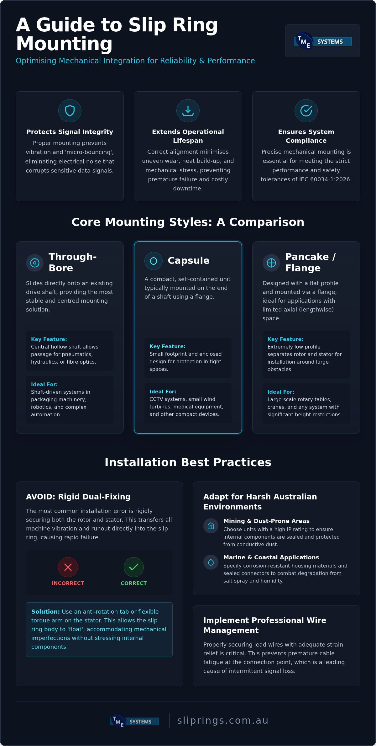
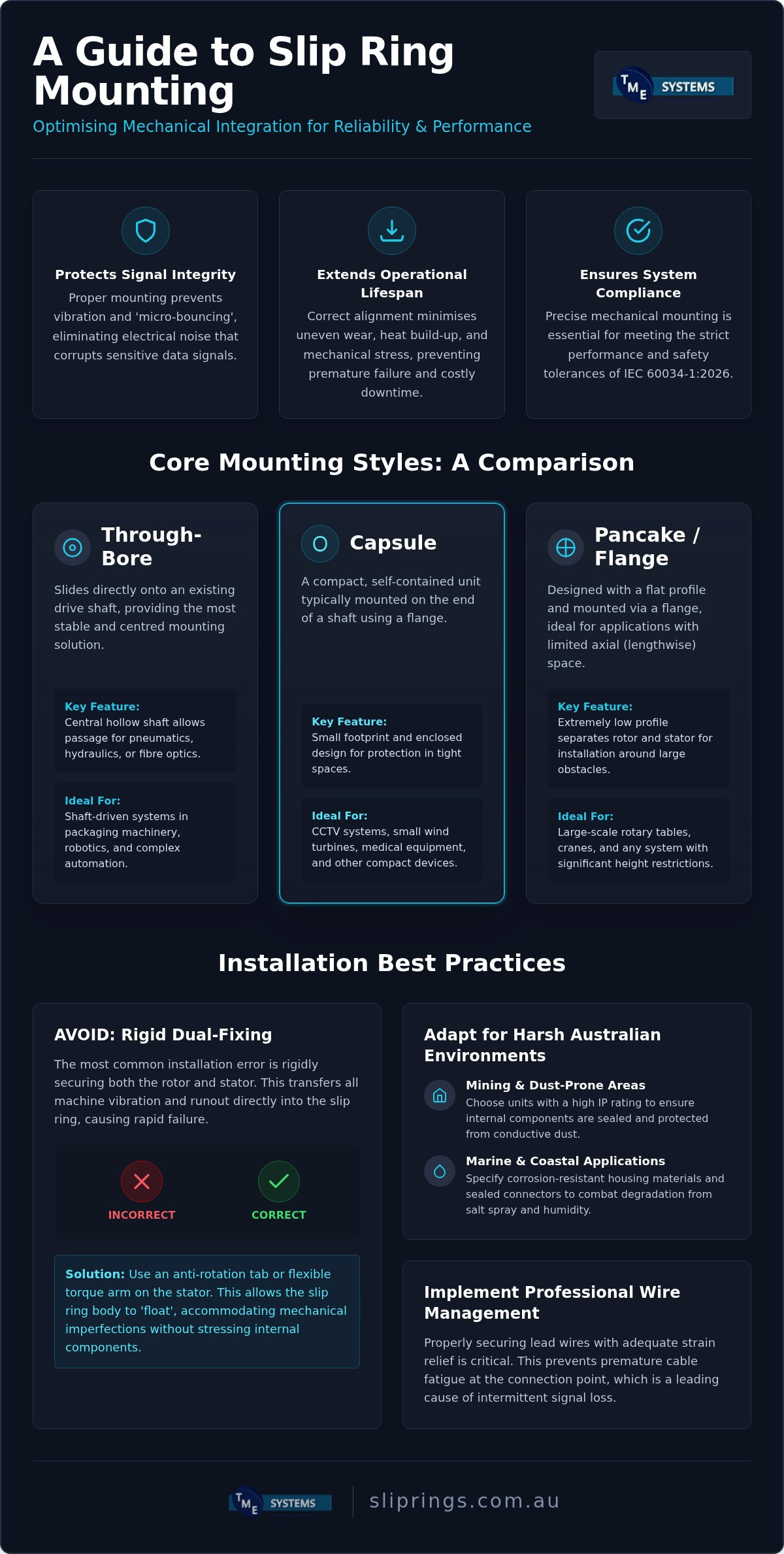
Mechanical mounting is far more than a simple physical attachment; it's the primary line of defence for protecting electrical signal integrity from rotational stress. While selecting the right slip ring mounting options might seem straightforward, the way a unit is secured often dictates whether it lasts for years or fails within months. You've likely seen how even minor misalignments can lead to premature cable fatigue or intermittent signal noise, especially when operating in the harsh, dust-prone environments common across Australian industrial sites.
Mastering these mechanical configurations is essential to prevent common failures and ensure your equipment remains compliant with the latest IEC 60034-1:2026 standards. This guide provides a technical roadmap for identifying the correct configuration for your specific shaft requirements, whether you're integrating Mercotac liquid-metal connectors or BGB Innovation systems. We will examine the functional differences between through-bore, capsule, and pancake styles to help you optimise space and eliminate mechanical strain on your rotary interfaces.
Key Takeaways
- Identify the optimal mechanical interface for your application by comparing through-bore, capsule, and flange configurations to match specific shaft requirements.
- Avoid the critical error of rigid dual-fixing by implementing anti-rotation tabs and torque arms to accommodate mechanical runout and prevent internal stress.
- Select the most durable slip ring mounting options for harsh Australian environments, with specific focus on sealing for mining dust and corrosion resistance for marine applications.
- Protect long-term signal integrity by applying professional lead wire management and strain relief techniques that prevent premature cable fatigue.
- Ensure your rotary systems remain compliant with IEC 60034-1:2026 standards through precise mechanical alignment and thorough pre-installation testing.
Understanding Slip Ring Mounting and Mechanical Integration
Mechanical integration is the physical bridge between a stationary structure and a rotating assembly. It's the foundation for all electrical performance. In Australian industrial sectors, from heavy mining in the Pilbara to high-speed packaging in Melbourne, the choice of slip ring mounting options is a critical engineering decision. This interface must manage the transfer of power and data while simultaneously withstanding the mechanical stresses of continuous rotation. When you treat mounting as an afterthought, you risk compromising the entire system's reliability.
The mounting choice directly dictates the lifespan of internal contact surfaces. Whether a unit uses traditional carbon brushes or advanced liquid-metal interfaces, these components rely on consistent, stable contact. Mechanical misalignment creates uneven wear patterns and heat build-up. Over time, this leads to premature failure and costly downtime. For Australian operators, where replacement parts often travel vast distances, ensuring a robust mechanical fit from day one is a pragmatic necessity for operational uptime.
The Link Between Mounting and Signal Integrity
Mechanical vibration is a primary source of electrical interference. If a mounting configuration allows for excessive runout, the internal contacts may experience "micro-bouncing." This introduces electrical noise that can corrupt sensitive data signals or cause fluctuations in power delivery. Maintaining stable resistance requires precise mechanical centring to ensure the rotor and stator remain perfectly aligned throughout their 360-degree travel.
Axial and radial play also accelerate contact wear. According to the IEC 60034-1:2026 standard for rotating electrical machines, maintaining specific tolerances is essential for safety and performance. This slip ring overview provides a foundational look at how these devices function, but it's the mechanical stability provided by the mount that preserves that function in the field. Without a rigid, well-aligned interface, even the highest quality electrical components will degrade rapidly under the strain of mechanical oscillation.
Identifying Your Mechanical Interface
Before selecting a unit, you must assess the drive system's physical characteristics. Is the assembly shaft-driven or flange-driven? A shaft-driven system often requires a through-bore design that slides directly over the existing equipment. Conversely, a flange-driven setup might be better suited for applications where the slip ring is bolted to the end of a shaft. You should also determine if the application requires through-bore access for auxiliary lines, such as hydraulics or pneumatics, which are common in complex robotic cells.
Spatial constraints within the machine housing will further narrow your slip ring mounting options. In compact Australian manufacturing environments, every millimetre of footprint matters. You'll need to evaluate the available volume for the housing, the clearance for lead wires, and the accessibility for future maintenance. Identifying these mechanical parameters early prevents the common pitfall of selecting a unit that's electrically perfect but physically impossible to install correctly.
Core Mounting Styles: Through-Bore, Capsule, and Flange
Choosing between different slip ring mounting options requires a clear understanding of your machine's mechanical architecture. Each configuration serves a distinct purpose, balancing the needs for rotational speed, space availability, and environmental protection. For instance, a high-speed centrifuge requires a different interface than a slow-moving palletiser. By selecting a style that matches your existing drive hardware, you reduce the risk of mechanical runout and electrical noise.
Through-Bore Integration (Hollow Shaft)
The through-bore or hollow shaft design is the standard for applications requiring the slip ring to be mounted directly onto an existing drive shaft. This configuration centres the unit on the mechanical axis, which is the most effective way to minimise vibration and eccentric motion. Beyond electrical transmission, the central bore provides a convenient passage for secondary lines. This is particularly useful in packaging machinery where you might need to route pneumatic hoses, hydraulic lines, or even fibre optic cables through the centre of the assembly. The Prosper Rotation range offers a variety of bore sizes to accommodate these multi-media requirements without increasing the overall footprint of the machine.
Capsule and Flange Mounting for Compact Spaces
When internal housing space is at a premium, capsule slip rings offer a fully enclosed, "plug-and-play" solution. These units are frequently used in CCTV systems, medical equipment, and small-scale robotics. The primary advantage of a capsule design is its pre-sealed housing, which protects the internal contacts from dust and moisture. For precision tasks that demand high rotational speeds, Meridian Laboratory high-speed capsules provide the low-noise performance necessary for sensitive data transfer. These compact units simplify installation because they don't require the complex alignment procedures associated with larger, modular systems.
Flange mounting provides a stable footprint for heavy-duty or high-vibration environments. By bolting the stator directly to a bulkhead or mounting plate, you ensure the assembly remains rigid even under significant mechanical load. If vertical height is your primary constraint, pancake designs offer a flat, disc-like alternative. While pancake models are generally limited to lower speeds due to their larger contact diameters, they're indispensable in applications like revolving doors or crane pedestals. If you're unsure which configuration fits your torque or RPM requirements, our team provides technical application consulting to help you select the most reliable interface from the BGB Innovation or Prosper catalogues.
Critical Auxiliary Features: Anti-Rotation and Torque Arms
The most critical rule in mechanical integration is that you must never rigidly fix both the rotor and the stator. This is a non-negotiable principle when evaluating slip ring mounting options. If both ends are bolted down firmly, any minor misalignment between the drive shaft and the mounting surface will exert massive radial forces on the internal bearings. This leads to rapid mechanical wear, increased electrical noise, and eventually, a total seizure of the unit. It is the most frequent cause of premature failure we see in the field.
An anti-rotation tab serves as a "floating" constraint that prevents the housing from spinning while allowing it to move slightly to accommodate mechanical runout. By using this method, you allow the slip ring's own internal bearings to define the rotational centre. This prevents the mounting hardware from fighting against the natural rotation of the shaft. It's a simple mechanical safeguard that preserves the precision of the internal contact surfaces and maintains consistent electrical resistance.
Why You Must Use an Anti-Rotation Tab
This feature is vital for protecting your lead wires from being twisted or sheared during operation. Without a proper constraint, the stator housing would eventually rotate due to internal bearing friction, causing the stationary cables to wrap around the assembly. In many industrial settings across Australia, we see failures where engineers have tried to solve rotation by over-tightening the mount, only to cause binding. A properly implemented anti-rotation tab ensures the housing stays stationary without being under tension. It effectively decouples the stationary wiring from the mechanical forces of the rotating shaft.
Managing Mechanical Stress and Shaft Runout
No drive shaft is perfectly straight. There is always some degree of wobble or runout, particularly in heavy machinery used in the mining or agricultural sectors. Slip ring mounting options must account for this by using flexible couplings or torque arms that can absorb mechanical shock and vibration. These components act as a buffer between the raw power of the drive system and the delicate electrical interfaces inside the slip ring.
Torque arms are specifically designed to handle the start-stop forces of high-torque motors. They should be installed with enough clearance to allow for axial and radial movement. If the mounting is too rigid, it introduces side-loading on the bearings. This side-loading is a silent killer of slip rings; it generates heat and degrades the contact surfaces long before the electrical components would naturally fail. Ensuring the mounting does not introduce these parasitic loads is the hallmark of a professional installation. Don't make the mistake of over-tightening these mounts; the goal is a secure but flexible interface.
Application-Specific Mounting in Australian Industry
Australian industrial environments present unique challenges that go far beyond basic mechanical compatibility. When you're selecting slip ring mounting options, the environmental stressors of the specific site must dictate the hardware configuration. A mounting setup that performs well in a clean, climate-controlled laboratory will likely fail within weeks on a remote mining site or a coastal marine facility. Tailoring the mechanical interface to the local conditions is a pragmatic necessity for maintaining long-term signal integrity and operational uptime.
High-Vibration Environments (Mining and Heavy Plant)
Heavy plant equipment, such as vibrating screens and reclaimers in the Pilbara, subjects rotary connectors to relentless mechanical shock. In these high-vibration settings, integration must involve more than just a standard bracket. We often utilise BGB Innovation heavy-duty housings because they're engineered to maintain electrical continuity under extreme physical stress. To protect the internal contact surfaces, you should implement reinforced mounting brackets combined with specialised dampening solutions. These dampeners decouple the slip ring from the machine's natural frequency, preventing the internal brushes from "chattering" against the rings, which would otherwise cause significant data corruption and accelerated wear.
Washdown and Corrosive Environments
In the Australian food and beverage sector, hygiene and washdown protocols are the primary drivers for mounting design. Brackets should be constructed from 316-grade stainless steel rather than anodised aluminium to resist the caustic cleaning agents used in these facilities. When evaluating your slip ring mounting options, you must ensure the unit's orientation prevents liquids from pooling around cable glands or electrical entry points. For marine applications exposed to constant salt spray, IP65 or IP67 rated connectors are essential. The mounting interface must be designed to maintain the integrity of these seals, ensuring no axial or radial stress is placed on the housing gaskets during operation.
Precision robotics and high-speed automation require a different focus. In these applications, the mounting must be perfectly concentric to avoid high-frequency noise that can interfere with sensitive control signals. Even a fraction of a millimetre of misalignment can introduce enough electrical "jitter" to trigger a system fault. If you are designing a system for a specific Australian industrial environment, our technical team can help you consult on custom mounting requirements to ensure your hardware is fit for purpose and survives the rigours of the field.
Best Practices for Professional Installation and Procurement
Successful mechanical integration concludes with a rigorous installation protocol. Even the most appropriate slip ring mounting options won't deliver their rated service life if the physical installation is flawed. Precision is the priority. Before any hardware is secured, you must ensure the environment is prepared to receive the component. This methodical approach prevents the "infant mortality" failures often seen in poorly planned retrofits or new builds across Australian worksites.
Pre-Installation Mechanical Audits
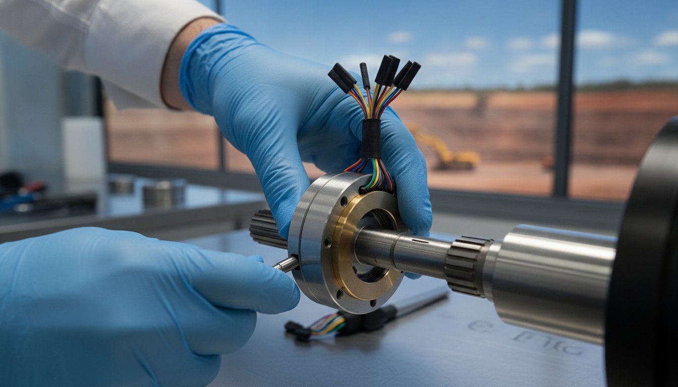
A comprehensive mechanical audit begins with the drive shaft itself. You must clean the shaft thoroughly to remove burrs, rust, or debris that could prevent a concentric fit. Verifying shaft tolerances and surface finishes ensures the inner diameter of a through-bore unit matches the shaft exactly. In high-temperature zones, you'll need to account for thermal expansion by providing sufficient axial clearance. Performing a "dry fit" of the assembly before final electrical termination allows you to check for binding or excessive runout without risking damage to the internal contact surfaces.
Lead wire management is equally critical. You must provide adequate strain relief to ensure that the weight of the cables doesn't pull on the housing or the internal terminals. Cable fatigue is a common failure point; use flexible conduit or cable ties to organise the wiring while allowing for the necessary movement defined by your anti-rotation setup. If the wiring is left unsupported, the constant vibration of industrial machinery will eventually lead to intermittent signals or open circuits. Electrical testing should also be conducted post-installation to verify that no noise has been introduced during the mounting process.
Technical Support from TME Systems Pty Ltd
Procurement should always involve a consultation with slip ring application engineering experts. This is especially important when specifying a Mercotac liquid-metal connector, as these units have specific mounting orientation requirements to maintain the integrity of the conductive fluid. Unlike traditional brush-based systems, liquid-metal units are often restricted to vertical or horizontal planes. Choosing the wrong configuration for your mounting orientation can lead to fluid leakage or immediate electrical failure.
At TME Systems Pty Ltd, we assist Australian engineers in selecting the correct industrial slip rings for their specific operational parameters. Whether you require custom mounting solutions for legacy equipment retrofits or standard units from our Prosper or BGB catalogues, our Australian-based team provides the technical assistance needed to ensure a perfect fit. We offer national delivery and local support to help you navigate the complexities of slip ring mounting options, ensuring your project meets both performance goals and current IEC 60034-1:2026 standards.
Securing Long-Term Reliability in Rotary Systems
Selecting the most appropriate slip ring mounting options is a fundamental step in ensuring the longevity of your industrial machinery. By prioritising precise mechanical alignment and adhering to the "floating" stator rule, you protect internal contacts from the parasitic loads that cause premature failure. Whether you're operating high-speed automation in a laboratory or heavy plant in a remote mining region, the physical interface defines the reliability of your electrical data and power transmission.
As the authorised Australian distributor for Mercotac and Meridian Laboratory, TME Systems Pty Ltd brings over 20 years of technical experience to your project. Our team provides specialist application engineering support to help you navigate complex integration challenges and ensure your hardware meets the latest IEC 60034-1:2026 standards. Consult TME Systems Pty Ltd for expert slip ring mounting advice to secure a robust, high-performance solution for your next installation.
Proper mechanical integration is a pragmatic investment that pays dividends in reduced maintenance and extended equipment life. We look forward to helping you optimise your rotary interfaces for the most demanding Australian conditions.
Frequently Asked Questions
Can I mount a slip ring in any orientation (horizontal vs vertical)?
Orientation depends entirely on the internal contact technology used in the device. Standard brush-based slip ring mounting options generally allow for any orientation without affecting performance. However, Mercotac liquid-metal units are orientation-sensitive due to the conductive fluid inside. You must verify the specific model's datasheet, as some are designed exclusively for vertical use. Installing these units incorrectly can lead to fluid leakage and immediate electrical failure.
What happens if I rigidly mount both the shaft and the housing?
Rigidly fixing both the shaft and the housing will lead to rapid mechanical seizure. This common error forces the internal bearings to absorb all mechanical runout and thermal expansion from the drive system. The resulting radial stress creates heat and uneven contact wear. You must always allow one side to "float" using an anti-rotation tab to ensure the bearings aren't subjected to parasitic loads.
How much shaft runout can a standard through-bore slip ring tolerate?
Most industrial units tolerate a maximum radial runout of 0.1mm to 0.3mm. While some through-bore models can handle slightly more, excessive wobble introduces electrical noise and "brush bounce." For high-speed applications, even tighter tolerances are required to maintain signal integrity. If your shaft has significant runout, you should utilise a flexible coupling to decouple the slip ring from the mechanical oscillation.
Do I need special tools to mount a Mercotac liquid-metal slip ring?
You don't need specialised tools for Mercotac installations, but you must follow strict orientation guidelines. Standard spanners and mounting hardware are sufficient for the physical attachment. The critical factor is ensuring the unit remains within the specified tilt angles to prevent the liquid metal from shorting or leaking. Always prioritise the technical datasheet's alignment instructions over general mechanical assembly practices to ensure long-term performance.
Should the anti-rotation tab be bolted tightly to the machine frame?
The anti-rotation tab should never be bolted tightly to the machine frame. It's designed to be a loose, floating constraint that prevents the stator from spinning while allowing for minor mechanical movement. Bolting it down rigidly creates a "dual-fixed" condition that introduces side-loading on the internal bearings. This leads to vibration, increased electrical noise, and premature failure of the contact surfaces.
How do I choose between a flange mount and a simple capsule mount?
Base your decision on the available space and the mechanical load of the environment. A flange mount provides a rigid, stable footprint ideal for high-vibration mining or heavy plant applications. In contrast, a capsule mount is better suited for compact, enclosed spaces like CCTV housings or small robotics. Capsule designs often come pre-sealed, making them a pragmatic choice for washdown areas where space is at a premium.
What is the most common cause of mounting failure in industrial environments?
The most frequent cause of failure is the rigid mounting of both the rotor and the stator. This mistake forces the slip ring to act as a load-bearing component for the drive shaft. It rapidly destroys the internal bearings and shears lead wires as the housing attempts to rotate. Ensuring one side remains flexible is the single most effective way to extend the lifespan of your rotary interface.
Are there specific mounting requirements for high-speed slip rings over 5000 RPM?
High-speed applications over 5000 RPM require exceptional concentricity and dynamic balance. At these velocities, even minor mounting misalignments generate significant centrifugal forces and vibration. You should use a through-bore design to centre the mass on the rotational axis and minimise runout. Precision-balanced slip ring mounting options are essential here to prevent the internal contacts from losing stable connection due to high-frequency oscillation.