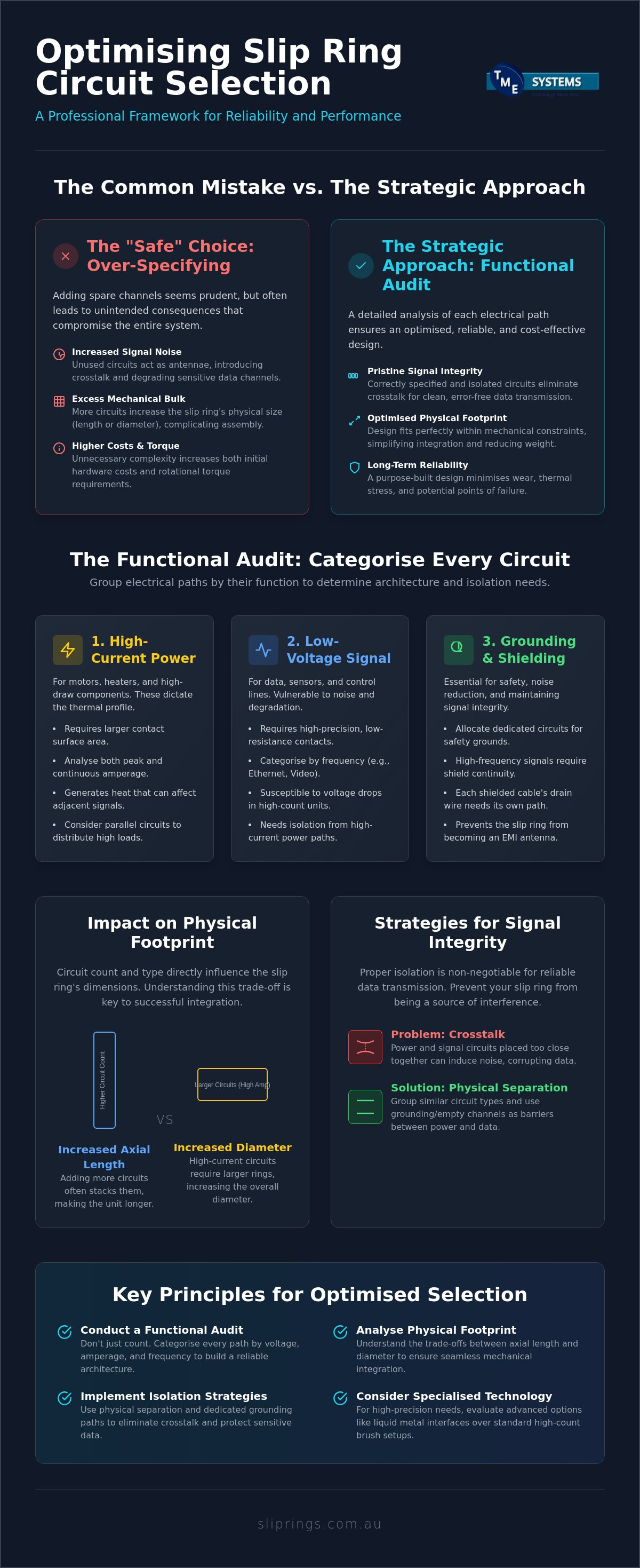
The "safe" choice of adding spare channels to your rotary interface might actually be the very thing that compromises your signal integrity. While it's tempting to over-specify for future needs, this approach often introduces unnecessary signal noise and mechanical bulk that complicates your assembly. You've likely faced the challenge of trying to maintain a compact physical footprint while ensuring that power and data lines don't interfere with one another, all while keeping a close eye on rising hardware costs.
We recognise that successful slip ring circuit count selection is a strategic grouping exercise rather than a simple counting task. This professional reference will help you master the technical nuances of determining the ideal circuit count to ensure long-term reliability. We'll provide a clear framework for circuit categorisation, showing you how to optimise your rotary joint's footprint and eliminate interference in your most sensitive data channels.
Key Takeaways
- Conduct a functional audit of all electrical lines to categorise paths by voltage, amperage, and frequency for a more reliable architecture.
- Understand how slip ring circuit count selection impacts the physical footprint of your assembly, including the trade-offs between axial length and diameter.
- Implement physical separation and isolation strategies within the rotary joint to eliminate crosstalk and maintain signal integrity across data channels.
- Determine when specialised contact technologies, such as liquid metal interfaces, are the most effective choice for high-precision transmission compared to high-count brush configurations.
Defining the Circuit: Fundamentals of Rotary Electrical Connections
A circuit in a slip ring is an independent electrical path that facilitates the transfer of power or data across a rotating interface. To understand What is a Slip Ring? at its most basic level, you must look at the physical interaction between the stator and the rotor. Each individual circuit requires two distinct points of contact: the stationary brush (the stator) and the rotating ring (the rotor). As the rotor turns, the brush maintains a constant connection, ensuring the electrical flow remains uninterrupted despite the mechanical movement.
The "count" in your slip ring circuit count selection represents the total number of these isolated paths available within a single assembly. It isn't just a tally; it's a blueprint for the unit's internal architecture. Getting this number right is the foundational step in ensuring your equipment maintains electrical performance without mechanical interference. If you under-specify, you lack the necessary lanes for operation. If you over-specify without cause, you risk increasing the rotational torque and physical size beyond what your application can handle. Every path added increases the complexity of the internal stack, making precision vital from the outset.
Power vs Signal Channels
Not all circuits are created equal. Power paths are designed to carry high current, which necessitates larger contact surface areas to manage heat and prevent arc damage. In contrast, signal channels handle low-voltage data. These require high-precision contact to avoid signal degradation. In high-count assemblies, low-level signals are particularly vulnerable to voltage drops. If the circuit count is high, the cumulative resistance across multiple interfaces can lead to data loss or "ghosting" in sensitive monitoring equipment. You must categorise your circuits based on their specific amperage and voltage requirements before finalising your selection. This prevents a scenario where a heavy power draw on one ring interferes with a delicate data stream on another.
Grounding and Shielding Requirements
Effective circuit count selection must account for more than just active lines. Dedicated grounding circuits are vital for both operator safety and electrical noise reduction. Beyond basic grounding, shielded cables used for high-frequency data require their own circuit allocations for the drain wire. You can't simply "bunch" shields together if you want to maintain signal integrity. Maintaining shield continuity through the rotary joint is essential to prevent the slip ring from acting as an antenna for electromagnetic interference. Ensure your count includes these auxiliary paths to protect your data streams from external noise. A well-planned ground path is often the difference between a clean signal and a corrupted one.
Categorising Your Requirements: A Functional Audit
A successful slip ring circuit count selection begins with a comprehensive audit of every electrical line that must cross the rotating axis. This isn't merely a tallying exercise. You need to map out the specific functional requirements of each line to ensure the hardware can handle the load without failure. Start by documenting the voltage, peak amperage, and frequency of every path. This data allows you to group circuits with similar electrical profiles, which is a critical step before you commit to a specific hardware configuration. Recognising mission-critical paths early helps you decide which circuits require high-reliability contact technologies and which can be handled by standard configurations.
When conducting this audit, referring to technical standards like those found in a high-performance slip ring handbook can provide a structured framework for managing environmental and operational variables. You should also determine if your application requires hybrid transmission. It's common for modern industrial machinery to require a combination of electrical circuits and pneumatic or hydraulic passes. Consulting a specialised slip ring supplier during this audit phase often reveals opportunities to consolidate circuits or use shared grounds, preventing an over-complicated design that could lead to higher maintenance costs down the track.
High-Current Power Circuits
High-current circuits for motor drives or heaters demand the most physical space within the assembly. You must assess both peak and continuous current requirements, as these directly influence the thermal profile of the unit. Excessive heat from a power ring can migrate to adjacent signal rings, causing data errors or material fatigue. In cases where amperages are extremely high, using parallel circuits is a common strategy to distribute the load across multiple rings. This approach manages the thermal load effectively, though it naturally increases your total circuit count and the physical length of the stack.
Sensitive Data and Signal Circuits
Data protocols like Ethernet, Profibus, or CAN bus require a low-noise environment to function reliably. This is where understanding slip ring contact resistance becomes vital. Even minor fluctuations in resistance can corrupt high-speed data streams or cause intermittent signal loss. For ultra-low voltage paths, such as thermocouple signals and other milli-volt applications, the choice of contact material is as important as the circuit count itself. These sensitive lines often require dedicated shielding and specific isolation from power rings to maintain signal integrity. If you're currently mapping out a complex interface, reaching out for technical application consulting can help clarify the most efficient way to group these channels.
The Physical Impact of Circuit Count on Slip Ring Selection
Once you've completed your functional audit, the next hurdle is fitting those requirements into your machine's physical envelope. Your slip ring circuit count selection directly dictates the final dimensions of the hardware. Generally, adding circuits forces a choice: do you extend the axial length or expand the diameter? Capsule slip rings are often the go-to for high circuit counts in tight spaces, offering a compact length but limited diameter. However, if you're working with a central drive shaft, through-bore designs allow you to stack more circuits along the shaft's length without necessarily increasing the unit's width.
As the count grows, so does the mechanical resistance. Each additional circuit introduces more brush-to-ring contact points. This increases the starting and running torque required to rotate the assembly. For precision robotics or sensitive instrumentation, this extra drag can affect performance. Weight also becomes a factor, especially in mobile applications where every gram counts. Balancing the electrical need for more paths against these mechanical realities is a core part of the engineering process. You don't want to over-specify and end up with a unit that's too heavy or difficult to drive.
Diameter vs Length Constraints
Pancake slip rings provide a solution for applications where vertical height is restricted but diameter is available. These units arrange circuits on a flat plane rather than a vertical stack. For projects requiring a modular approach, Prosper Rotation slip rings are frequently specified because they allow for flexible circuit configurations within standard housing sizes. Your mounting style, whether it's end-of-shaft or through-bore, will ultimately determine which physical trade-off is most manageable for your specific rig.
RPM and Thermal Dissipation
High-count units generate more internal friction, which translates to heat, particularly at high RPM. Efficient thermal dissipation is crucial, especially in harsh Australian environments where ambient temperatures are already elevated. When high speed and signal precision are both required, a Meridian Laboratory unit is often the most reliable choice. These units are engineered to handle high-speed rotation while maintaining signal integrity. It's worth noting that the number of circuits that can be realistically packed into such high-performance hardware is often lower than in slower, larger industrial stacks. If you're pushing for high speeds, you'll need to be more disciplined with your circuit count to avoid overheating the assembly.
Managing Interference: Isolation and Redundancy
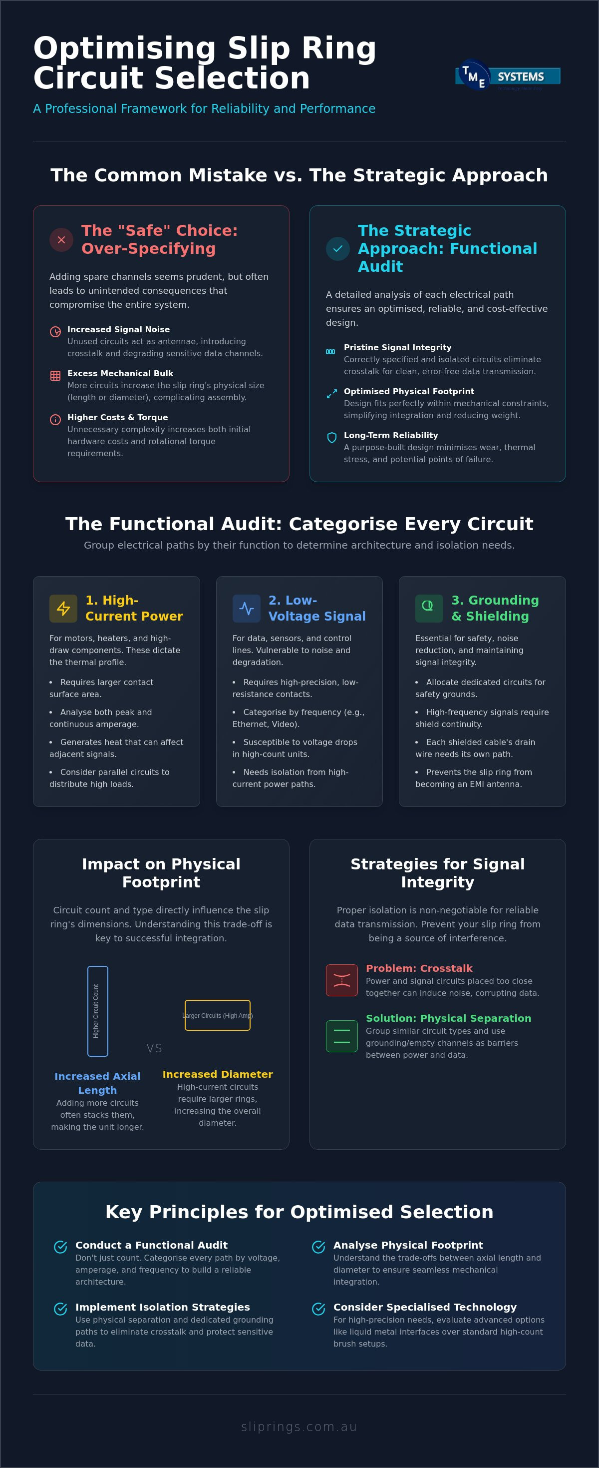
The primary hurdle in high-density assemblies is managing electromagnetic interference (EMI). When power and signal lines are packed into a single housing, crosstalk is almost inevitable without proper isolation. This is why slip ring circuit count selection must be viewed as a spatial arrangement task. Physical separation is your best defence. By placing grounded "spacer" circuits between high-voltage power lines and delicate data paths, you create an effective electrical buffer. This strategy prevents noise from bleeding into your signal channels and compromising data integrity.
Redundancy is another critical factor for long-term reliability. For essential systems, such as safety interlocks or primary control signals, allocating duplicate circuits is a pragmatic insurance policy. It prevents a single brush failure or ring wear-point from causing a total system shutdown. While this increases the initial circuit count, the reduction in potential downtime makes it a sound engineering choice for mission-critical rigs.
Strategic Circuit Grouping
Internal wiring must be organised with precision. Place your most sensitive signals as far as possible from power-heavy rings to minimise inductive coupling. Using twisted-pair wiring for your signal paths through the rotary joint provides an additional layer of noise rejection. For large-scale industrial applications, BGB Innovation slip rings often incorporate internal shielding barriers. These barriers act as physical partitions, ensuring that high-frequency interference remains isolated from low-voltage data streams, which is vital for maintaining clean communication in noisy electrical environments.
Planning for Spare Circuits
Future-proofing is a key part of the selection process. We suggest including a 10-20% margin of spare circuits in your initial design. This buffer allows for emergency bypasses if a circuit fails or for future upgrades without requiring new hardware. The cost of adding a few extra rings during initial manufacture is negligible compared to the expense of a full replacement later. As industrial IoT and sensor integration become standard, those spare paths will prove invaluable for adding monitoring capabilities to your existing machinery. If you are unsure about the best way to balance spare capacity with physical size, you can consult with our technical team for a tailored recommendation.
Expert Consultation for Optimised Rotary Interfaces
The final stage of slip ring circuit count selection involves aligning your audited requirements with the most appropriate contact technology. Not all internal architectures are compatible with high circuit densities, and choosing the wrong medium can lead to premature failure or signal degradation. For example, liquid metal connectors like Mercotac slip rings are engineered for superior signal quality in low-count applications, typically supporting up to 8 circuits. These units provide near-zero maintenance and exceptionally low electrical noise. However, if your application demands dozens of paths for heavy industrial power and complex data, conventional brush-and-ring systems remain the industry standard for their scalability.
TME Systems Pty Ltd provides technical application consulting to ensure your hardware selection meets Australian industrial standards. We look beyond the simple tally of wires to evaluate how the contact technology will perform under your specific operational loads. This professional oversight prevents common errors, such as selecting a high-count brush system for a sensitive data application that would be better served by a specialised low-noise interface. By matching the technology to the complexity of your circuit map, you ensure the long-term reliability of the entire rotary assembly.
Matching Technology to Circuit Complexity
Your choice hinges on the trade-off between signal precision and circuit volume. Understanding how a slip ring works helps clarify why certain technologies have inherent circuit limits. Mercotac is the preferred solution for high-speed, low-noise signal transfer where the circuit count is modest. For heavy-duty power requirements or massive circuit counts, specifying BGB or Prosper assemblies provides the necessary robustness. These modular systems allow for extensive stacking that liquid metal interfaces cannot physically accommodate, making them ideal for large-scale industrial machinery.
The TME Systems Pty Ltd Selection Process
Our team assists in consolidating circuits to reduce the physical footprint of the rotary joint. We require specific data points to perform a professional selection, including your operating RPM, peak current, voltage levels, and environmental conditions. We analyse these variables to determine if you can share grounds or use parallel paths to optimise the assembly. This methodical approach ensures you don't over-specify and pay for capacity that isn't required for your application. Contact TME Systems Pty Ltd for a technical audit of your rotary connection requirements to ensure your project is built on precise, reliable specifications.
Optimising Your Rotary Interface for Long-Term Reliability
Determining the right configuration is more than a clerical task; it's a critical engineering decision that affects the mechanical and electrical health of your entire system. By auditing your voltage and frequency requirements and planning for physical isolation, you prevent the crosstalk and interference that often plague poorly specified units. Precise slip ring circuit count selection ensures your assembly remains compact while providing the necessary lanes for power and high-speed data without compromising signal integrity.
As the authorised Australian distributor for world-class brands like Mercotac, Meridian Laboratory, BGB, and Prosper, TME Systems Pty Ltd provides the technical expertise required for high-performance rotary transfer. Our team in Ingleburn, NSW, offers the application support needed to avoid the unnecessary costs of over-specification while ensuring compliance with local industrial standards. We're here to ensure your hardware is matched perfectly to your operational environment.
Consult with TME Systems Pty Ltd for expert slip ring circuit selection to secure a rotary solution that performs reliably under any industrial load. We look forward to helping you optimise your next project with precision and technical excellence.
Frequently Asked Questions
How many circuits can a standard industrial slip ring handle?
The capacity varies significantly based on the contact technology and housing size. Compact capsule units typically handle between 6 and 24 circuits, while large industrial stacks from manufacturers like BGB or Prosper can accommodate over 100 independent paths. Conversely, liquid metal units are generally restricted to 8 circuits or fewer to maintain their specialised seal integrity and low-noise performance.
Can I run power and Ethernet signals through the same slip ring?
Yes, you can run both power and Ethernet, provided the assembly is engineered with internal shielding and physical separation. Successful slip ring circuit count selection for hybrid use requires dedicated twisted-pair wiring for data lines to prevent electromagnetic interference from power circuits. Proper isolation is the only way to ensure high-speed data integrity while transferring heavy electrical loads through the same rotary joint.
What happens if I under-specify the circuit count for my application?
Under-specifying leaves you without enough independent paths, often forcing the risky practice of sharing grounds or daisy-chaining lines. This leads to increased electrical noise, potential safety hazards, and a total lack of flexibility for future upgrades. If you don't include enough circuits from the start, you'll likely face the high cost of a full hardware replacement when adding even a single sensor later.
Do spare circuits in a slip ring cause signal interference?
Spare circuits do not cause interference if they are managed correctly. In many high-performance designs, unused circuits are intentionally grounded to act as electrical "spacers" between high-voltage power rings and sensitive signal lines. This approach actually helps reduce crosstalk and improves the overall signal-to-noise ratio within the assembly, making spare capacity a functional benefit for isolation as well as future-proofing.
How does circuit count affect the maximum RPM of a rotary connector?
Higher circuit counts generally reduce the maximum allowable RPM because each additional contact point increases internal friction and heat generation. This cumulative thermal load can degrade lubricants and contact materials at high speeds. High-speed units, such as those from Meridian Laboratory, are often designed with a lower circuit density to ensure they can dissipate heat effectively while rotating at several thousand RPM.
Is it better to have one large slip ring or two smaller ones for high circuit counts?
A single integrated slip ring is usually the better choice for mechanical alignment and ease of installation. However, split systems can be advantageous if your application requires absolute isolation between high-current power and ultra-sensitive instrumentation. While two smaller units might solve specific EMI challenges, they double the number of mounting points and seal interfaces, which may increase your long-term maintenance requirements.
What is the difference between a circuit and a pole in slip ring terminology?
While these terms are sometimes used interchangeably, a circuit refers to the complete, independent electrical path through the rotating interface. A "pole" is a term more commonly borrowed from switchgear to describe an individual contact point. In the context of slip ring circuit count selection, we always define requirements by the total number of isolated electrical paths needed to carry your specific signals and power loads.
How do I determine the wire gauge needed for each circuit in my selection?
Wire gauge is dictated by the continuous and peak amperage requirements of the specific path. High-current circuits for motors or heaters require larger cross-sectional areas to prevent excessive voltage drops and heat buildup. You must balance these gauge requirements against the physical constraints of the slip ring housing, as larger wires will inevitably increase the total axial length or diameter of the final assembly.