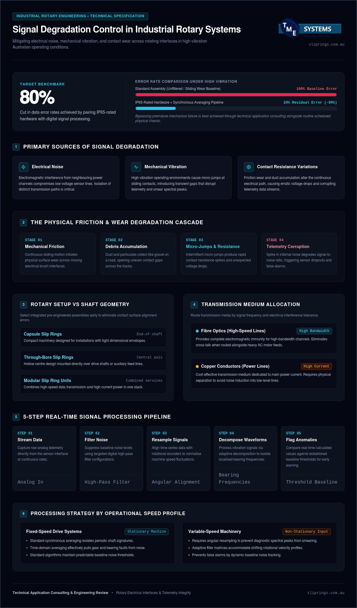
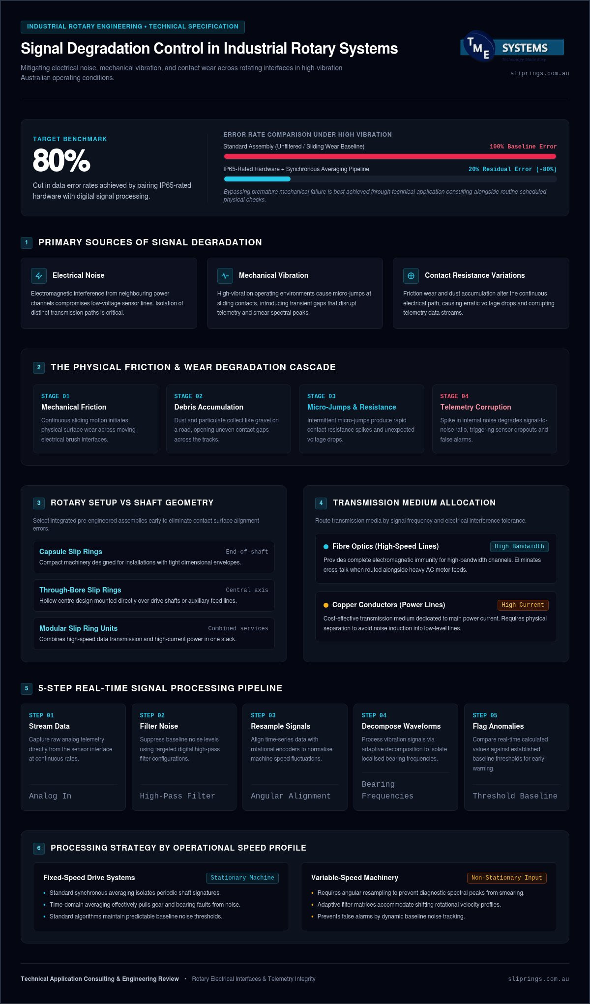
Signal degradation in industrial rotary systems stems primarily from electrical noise, mechanical vibration, and contact resistance variations. Selecting IP65-rated hardware and implementing targeted digital signal processing can cut data error rates by up to 80% in high-vibration Australian operating environments. Bypassing premature mechanical failure and signal degradation is achieved best through technical application consulting, even if physical inspections remain necessary due to hardware limits.
Key Takeaways: Reducing signal degradation in rotary systems requires pairing IP65-rated hardware with synchronous averaging to cut data error rates by up to 80%.
- Synchronous averaging effectively isolates periodic patterns from background noise by extracting signals tied directly to shaft rotation.
- Mechanical friction and dust accumulation in slip rings cause voltage drops and contact resistance variations that corrupt telemetry.
- Fibre optics provide superior electromagnetic immunity for high-bandwidth paths while copper remains the cost-effective choice for power.
- Unless you implement angular resampling, spectral peaks will smear during variable-speed operations on non-stationary machinery.
Your real decisions sit upstream of any filter setting: which rotary assembly matches the shaft and data load, which medium carries power versus high-speed channels, and how you isolate those paths so contact wear does not erase the noise margin you paid for.
Match Rotary Setup to Transmission Needs Before Signal Loss Starts
When mechanical layout and transmission path disagree, signal degradation shows up at commissioning, not after years of service. Selecting an integrated assembly yields higher system reliability because pre-engineered components eliminate alignment errors between contact surfaces.
Before you freeze the bill of materials, map the job to one of these patterns:
- Compact machinery with a tight envelope: standard capsule designs.
- A central drive shaft through the axis: through-bore models.
- Combined power and high-speed data on one rotator: modular units.
Review signal slip ring specifications against shaft geometry and channel count. Treating capsule, through-bore, and modular units as interchangeable ignores how contact geometry and cable exits behave under load. Think of the assembly as a relay team: a single poor contact point drops the baton. TME Systems Pty Ltd helps align these components to the duty cycle you run. Ask for a personalized quote.
How Friction and Wear Create Signal Loss in Rotating Machinery
If a stable sensor channel suddenly shows unexplained dropouts, the sliding interface is often where the path breaks first. Signal loss (signal degradation) occurs when mechanical friction and wear disturb the continuous electrical path across moving interfaces. When you troubleshoot an industrial sensor reading, unexpected voltage drops often point directly to wear on the rotating contacts. Mechanical motion creates physical friction that degrades sliding electrical interfaces over time.
Tracking a vibration signal (adaptive decomposition) helps you detect internal component wear before complete electrical failure. Accumulating debris acts like thrown gravel on a smooth road, causing micro-jumps in contact surfaces. Those momentary gaps spike the internal noise level (signal-to-noise ratio) and corrupt low-voltage telemetry lines. A durable heavy-duty collector ring assembly supplies mechanical protection for demanding operational environments. Technical application consulting, paired with scheduled inspection, limits exposure to signal degradation and early mechanical breakdown where hardware limits still require physical checks. Poor maintenance schedules worsen these failures: dust accumulation raises contact resistance rapidly, and wear opens uneven gaps.
Tip: Regularly inspect slip ring brush assemblies to prevent contact resistance variation from corrupting low-voltage sensor channels.
Processing Methods That Pull Fault Signatures Out of Background Noise
Digital cleanup only pays off after the physical path stops injecting interference at the brushes. Synchronous averaging cleans noise from rotating machinery by extracting periodic signals directly from background interference. The process isolates repetitive patterns tied to shaft rotation. Time-domain signal averaging isolates gear and bearing faults efficiently, and digital filtering improves signal loss metrics across operational cycles.
Filtering alone cannot fix a hardware setup that introduces heavy interference at the physical connection point. Learning how slip rings work helps you prevent initial mechanical distortion before digital processing begins. More on this: How Does a Slip Ring.
Variable-speed operations need angular resampling when you track non-stationary vibration signal inputs, otherwise spectral peaks smear. Adaptive filters fit complex, variable-speed machinery; standard synchronous processing suits fixed-speed drive systems. Advanced algorithms raise the baseline noise level for diagnostic monitoring so you spend less time chasing false alarms.
5 Steps That Keep Real-Time Signal Processing Usable
High sampling rates will swamp a processor that has no ordered pipeline, so structure the flow before you raise the sample clock. Real-time processing requires continuous data streams to detect immediate physical changes. From field deployments, high sampling rates quickly overwhelm onboard processors.
- Stream Data: Capture raw analog telemetry directly from the sensor interface.
- Filter Noise: Reduce the noise level using digital high-pass filters.
- Resample Signals: Align time-series data with rotational encoders to normalize speed fluctuations.
- Decompose Waveforms: Process the vibration signal to isolate localised bearing frequencies.
- Flag Anomalies: Compare real-time values against calculated baseline thresholds.
Managing high-frequency data streams means balancing computational load against hardware limits. For the rotary connection that feeds this pipeline, see modular slip ring designs. Continuous processing needs dedicated hardware sized so your digital signal processor does not overheat under sustained load, and a correct architecture stops processing delays before they mask real faults.
Copper or Fibre: Hardware Spend Versus Signal Integrity
The medium you choose sets both the invoice and the headroom against electromagnetic interference on the rotating path. Selecting copper or fibre optic media dictates your upfront hardware investment and resistance to signal loss. In high-speed data transmission, fibre optic lines offer strong immunity to electromagnetic noise level compared with traditional copper wiring. Copper remains cost-effective for simple electrical power delivery within basic assemblies. Fibre optics bypass electrical interference on high-bandwidth paths, whereas copper remains a practical workhorse for basic currents. Copper suits budget-conscious low-frequency setups; fibre optics fit high-bandwidth industrial rotators.
| Material | Primary Benefit | Relative Hardware Investment |
|---|---|---|
| Copper Wiring | Transmits power directly | Lower initial spend |
| Fibre Optics | High signal integrity | Higher initial spend |
Choosing optical hardware reduces data distortion across high speeds. Once the path mix is clear, request configuration pricing so hardware spend matches the noise margin your channels need.
Why Traditional Slip Rings Fail Under High-Speed Data Loads
At rising shaft speed, sliding contacts stop being a quiet bridge and start writing their own noise onto the bus. Traditional sliding contacts cause severe signal loss at high rotational velocities due to continuous physical friction and contact bounce. Physical brushes struggle to maintain consistent electrical contact when rotational speed increases, creating electrical noise and intermittent connectivity failures.
High speeds generate micro-vibrations that distort the noise level across the physical interface. Mechanical wear creates debris that degrades data integrity long before total mechanical failure occurs.
Relying on legacy brush assemblies for high-throughput networks sets an inherent bandwidth ceiling because physical contact cannot stay stable under continuous friction. Contactless rotary joints provide a reliable long-term alternative for gigabit-rate data transmission when sliding contacts cannot hold the required noise margin. Unsuitable hardware choices cannot be rescued by process advice alone; the contact method has to match the data rate.
Route Mixed Power and High-Speed Signals Without Cross-Talk
Power and low-voltage data share a housing only if you keep their paths electrically and physically apart. Isolate high-power lines from sensitive digital channels by routing them through separate channels, spatial tracks, or dedicated slip ring modules.
During installation testing, high-current circuits often act like broadcast antennas. Electromagnetic fields from power lines directly pollute adjacent data streams. Proper hardware sizing demands physical distance, heavy shielding, and strict grounding protocols. High-frequency digital pathways require precise impedance matching to prevent signal loss across rotating interfaces. That separation needs upfront planning if you want the noise level required for clean data transfers.
Route power along the outer slip rings and send high-speed data through twisted, shielded inner pairs. Short cable runs and twisted pairs reduce loop area; shielding limits EMI into the data path.
Tip: Always spec at least an IP65 housing rating for Australian outdoor industrial operations to guard sensitive data lines against fine dust and water ingress.
Frequently Asked Questions
What signal processing methods are used for rotating machine health monitoring?
Engineers filter dynamic raw data to remove unwanted background interference. Techniques include signal loss analysis alongside vibration signal methods. You need specialised software tools to isolate subtle mechanical fault frequencies effectively.
Can IP65 hardware and DSP reduce errors in high-vibration plants?
Yes. Selecting IP65-rated hardware and implementing targeted digital signal processing can cut data error rates by up to 80% in high-vibration Australian operating environments. Pair the enclosure rating with contact materials and filtering matched to your shaft speed and sensor voltage.
How do you choose copper versus fibre for rotary data?
Copper suits power delivery and budget-conscious low-frequency setups with lower initial spend. Fibre optics suit high-bandwidth industrial rotators when you need high signal integrity and strong immunity to electromagnetic noise, at higher initial spend.
Does higher RPM always increase noise?
Higher rotation speeds generally increase absolute vibration energy but do not automatically lower data clarity. Increased speeds can worsen mechanical unbalance issues. Proper sensor mounting prevents high-speed signal distortion.
Can slip rings support mixed power and signal channels?
Modern rotary assemblies route power and sensitive data across isolated conductive paths without mutual interference. Internal shielding prevents electromagnetic cross-talk between high-current circuits and delicate sensor lines. TME Systems Pty Ltd can supply custom slip ring configurations after an application review.
Achieving Precision in Rotary Data Transfer
Reducing signal loss in rotary systems requires balancing matched physical hardware ratings with targeted digital signal processing algorithms in 2026.
The same choices you face at the outset (assembly type for the shaft, copper versus fibre for each channel, isolation of power from data, and a processing pipeline the hardware can sustain) decide whether error rates stay controlled under vibration. Physical hardware choices must be paired with careful digital filtering to preserve system integrity. You can review optimal hardware configurations in the rotary signal integration documentation. More on this: Slip Ring FAQ.
On a high-vibration Australian line, dust and contact bounce corrupt low-voltage sensor channels until the path is sealed and the stream is filtered: IP65-rated hardware plus targeted digital signal processing is the pairing that can cut data error rates by up to 80%, provided the contact method and channel isolation already match the duty. The engineering team at TME Systems Pty Ltd provides custom slip ring specifications and technical guidance. Contact the advisers today for application-specific pricing on your rotary setup.